
Low-Cost Wireless Connectivity
In this chapter, we look at the basics of Bluetooth with the low-cost HC05 Bluetooth module. The chapter also discusses using Wi-Fi and the device that took the embedded market by storm, the ESP8266.
Integrating Wi-Fi
Wi-Fi is a type of protocol used for wireless networking. Wi-Fi allows a device to communicate over TCP/IP wirelessly. The most important parts of the Wi-Fi network are the Wireless Access Point (AP) , which is the epicenter of the communications, and a station, which is a device that has the ability to connect to an access point. In your home or office, this access point usually allows you to connect to the Internet.
Each device on your Wi-Fi network is assigned a MAC address, which is a unique 48-bit value that allows a particular node on a network to distinguish itself from another node.
One of the benefits of Wi-Fi is that it allows you to set up a network more cheaply and easily than when using a wired network. In the embedded systems context, it is easier to integrate Wi-Fi into your systems versus Ethernet since the Wi-Fi module we will examine is readily available. Writing your own TCP/IP tasks takes a lot of work.
In this section, we examine one of the simplest ways to integrate networking into your embedded systems.
Using the ESP8266
The ESP8266 is a little device that can be used for Wi-Fi communication. This little part is very inexpensive and is ridiculously inexpensive on the Chinese market. The ESP8266 can act as an access point or as a station within a Wi-Fi network. The ESP8266 was revolutionary in that it allowed embedded designers and makers to add wireless connectivity to their devices at a very low cost, with nothing else in that price range existing at the time it appeared.
Testing the ESP8266
The ESP8266 has a built-in processor that allows you to communicate with it via AT commands. Let’s look at some of these commands, which can be used to control the ESP8266.
Table 13-1 lists some commands that you can use to test your ESP8266.
Table 13-1 Some ESP8266 AT Commands
Command | Function |
|---|---|
AT | Tests if the AT system works OK. |
AT+RST | Resets the module. |
AT+GMR | Prints the version of the firmware installed on the ESP8266. |
AT+CWMODE? | Wi-Fi mode of the ESP8266. |
AT+CWJAP = SSID, PWD | Connects to SSID with the password specified. |
AT+CWLAP | Lists all available access points. |
Project: Wi-Fi Data Logger
In this project, we use the PIC16F1717 to send wireless data over Wi-Fi, which can be viewed in any web browser. We will set up the ESP8266 in server mode for a single connection. The PIC16F1717 does not have the RAM, ROM, or processing power to build a full web page. Since it only uses a baud rate of 9600 to communicate with the ESP8266, it would take too long to send a full web page and perform all the necessary checks to ensure that the ESP8266 is receiving commands. A web page would also use a good portion of the onboard storage of the microcontroller.
To compensate for this limitation, we will send the minimum commands necessary to set up the ESP8266 as a web server. We will also use the watchdog timer. The WDT will be used initially at a timeout of 4 seconds to ensure that the server starts up properly. Parsing all the required strings sent by the ESP8266 would add extra overhead. After the server is set up, the watchdog timer will be set to have a higher timeout of 128 seconds, up from the original 4 seconds.
The output of the ESP8266 can be viewed in any web browser once you get the IP address via your router. In your web address bar, type the IP of the device followed by :80/ and wait for it to load.
The schematics are shown in Figure 13-1.
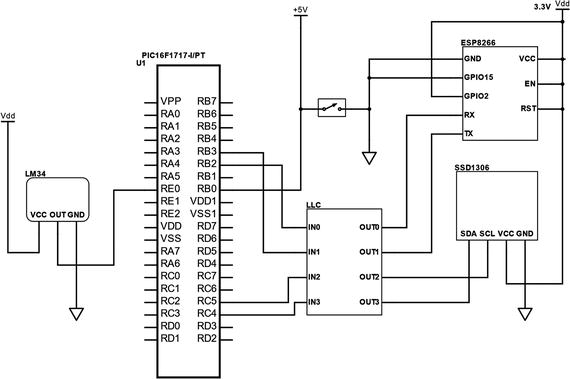
Figure 13-1 Wi-Fi logger schematics
Take a look at the code in Listing 13-1.
Listing 13-1 Wi-Fi Logger Source
/** File: Main.c* Author: Armstrong Subero* PIC: 16F1717 w/Int OSC @ 16MHz, 5v* Program: P03_IoT_WiFi* Compiler: XC8 (v1.41, MPLAX X v3.55)* Program Version: 1.0*** Program Description: This Program gives a reading in Celsius based on the* output of a LM34 temperature sensor which is then sent* via WiFi using the ESP8266 ESP-12-F the output of which* can be read in a web browser. The program uses the* watchdog timer initially with a timeout of 4s then* once the server is operational has a timeout of 128s* after which the server will reboot.** Hardware Description: A LM34 is connected to PIN E0 and a SSD1306 OLED is* connected to the I2C bus. The ESP8266 is connected as* follows:* VCC-> VCC* TX-> RB3* RD-> RB2* GPI015-> GND* GPI02-> VCC* REST-> VCC* EN-> VCC* VC-> VCC** External interrupt is connected to PINB0** Created March 31st, 2017, 10:57 AM*//********************************************************************************Includes and defines******************************************************************************/#include "16F1717_Internal.h"#include "I2C.h"#include "oled.h"#include "EUSART.h"#include <string.h>// Buffer for UART transactionschar buf[50];// Function prototypesfloat Read_Temperature();void server_Initialize();/******************************************************************************** Function: void initMain()** Returns: Nothing** Description: Contains initializations for main** Usage: initMain()******************************************************************************/void initMain(){// Run at 16 MHzinternal_16();/////////////////////// Set up All Serial////////////////////// Set up pins for I2CANSELCbits.ANSC4 = 0;ANSELCbits.ANSC5 = 0;TRISCbits.TRISC4 = 1;TRISCbits.TRISC5 = 1;PPSLOCK = 0x55;PPSLOCK = 0xAA;PPSLOCKbits.PPSLOCKED = 0x00; // unlock PPSRC4PPSbits.RC4PPS =0x0011; //RC4->MSSP:SDA;SSPDATPPSbits.SSPDATPPS =0x0014; //RC4->MSSP:SDA;SSPCLKPPSbits.SSPCLKPPS =0x0015; //RC5->MSSP:SCL;RC5PPSbits.RC5PPS =0x0010; //RC5->MSSP:SCL;// Set up pins for EUSARTRB2PPSbits.RB2PPS = 0x14; //RB2->EUSART:TX;RXPPSbits.RXPPS = 0x0B; //RB3->EUSART:RX;PPSLOCK = 0x55;PPSLOCK = 0xAA;PPSLOCKbits.PPSLOCKED = 0x01; // lock PPS////////////////////// Configure ADC///////////////////// Fosc/32 ADC conversion time is 2.0 usADCON1bits.ADCS = 0b010;// Right justifiedADCON1bits.ADFM = 1;// Vref- is VssADCON1bits.ADNREF = 0;// Vref+ is VddADCON1bits.ADPREF = 0b00;// Set input channel to AN0ADCON0bits.CHS = 0x05;// Zero ADRESL and ADRESHADRESL = 0;ADRESH = 0;// Set E0 as ADC input channel5ANSELEbits.ANSE0 = 1;/////////////////////// Set up EUSART Pins/////////////////////// Set up PINSTRISBbits.TRISB3 = 1;ANSELBbits.ANSB3 = 0;TRISBbits.TRISB2 = 0;ANSELBbits.ANSB2 = 0;//////////////////////////////////// Configure watchdog timer//////////////////////////////////// Set watchdog timeout for 4 secondsWDTCONbits.WDTPS = 0b01100;TRISDbits.TRISD1 = 1;ANSELDbits.ANSD1 = 1;// Set PIN B0 as inputTRISBbits.TRISB0 = 1;// Configure ANSELB0ANSELBbits.ANSB0 = 0;//////////////////////////// Configure Interrupts////////////////////////// unlock PPSPPSLOCK = 0x55;PPSLOCK = 0xAA;PPSLOCK = 0x00;// Set Interrupt pin to pin B0INTPPSbits.INTPPS = 0b01000;// lock PPSPPSLOCK = 0x55;PPSLOCK = 0xAA;PPSLOCK = 0x01;// Trigger on falling edgeOPTION_REGbits.INTEDG = 0;// Clear external interrupt flagINTCONbits.INTF = 0;// Enable external interruptINTCONbits.INTE = 1;// Enable global interruptei();}/******************************************************************************** Function: Main** Returns: Nothing** Description: Program entry point******************************************************************************/void main(void) {initMain();// Initialize I2CI2C_Init();__delay_ms(500);// Initialize OLEDOLED_Init();// clear OLEDOLED_Clear();__delay_ms(1000);CLRWDT();// Initialize EUSARTEUSART_Initialize(9600);// Indicate start of serverOLED_YX(0, 0);OLED_Write_String("START SERVER");__delay_ms(2000);CLRWDT();// Initialize the severserver_Initialize();// temperature variablefloat temp;while(1){// Clear OLEDOLED_Clear();/////////////////////////////////// Read and Display temperature////////////////////////////////temp = Read_Temperature();OLED_YX(0, 0);OLED_Write_String("Temperature:");OLED_YX(1, 0);OLED_Write_Integer(temp);__delay_ms(1000);OLED_Clear();/////////////////////////////////// Convert temperature to string////////////////////////////////char* buff11;int status;buff11 = itoa(&status, temp, 10);strcat(buff11, " ");/////////////////////////////////// Wait for connection request/////////////////////////////////EUSART_Read_Text(buf, 20);//////////////////////////////////////// Display some of the received data/////////////////////////////////////OLED_YX(1, 0);OLED_Write_String(buf);__delay_ms(3000);OLED_Clear();///////////////////////////////////////////// Send the temperature as 2 bytes of data//////////////////////////////////////////OLED_YX(0, 0);OLED_Write_String("Sending Data");EUSART_Write_Text("AT+CIPSEND=0,2 ");__delay_ms(5000);EUSART_Write_Text(buff11);EUSART_Read_Text(buf, 10);OLED_YX(1, 0);OLED_Write_String(buf);__delay_ms(3000);OLED_Clear();/////////////////////////// Close connection////////////////////////EUSART_Write_Text("AT+CIPCLOSE=0 ");__delay_ms(1000);EUSART_Read_Text(buf, 10);OLED_YX(1, 0);OLED_Write_String(buf);__delay_ms(3000);OLED_Clear();// Reset EUSARTRC1STAbits.SPEN = 0;RC1STAbits.SPEN = 1;// one this is complete clear watchdogCLRWDT();}return;}/******************************************************************************** Function: void interrupt isr(void)** Returns: Nothing** Description: Interrupt triggered on pushbutton press******************************************************************************/void interrupt isr(void){// Clear interrupt flagINTCONbits.INTF = 0;// Set watchdog timeout for 4 secondsWDTCONbits.WDTPS = 0b01100;// Re-initialize serverserver_Initialize();}/******************************************************************************** Function: void server_Initialize(void)** Returns: Nothing** Description: Sets up ESP8266 as single connection server on port 80******************************************************************************/float Read_Temperature(){float conversion10;float farenheit;float celsius;float result;// Turn ADC onADCON0bits.ADON = 1;// Sample CH0__delay_us(10);ADCON0bits.GO = 1;while (ADCON0bits.GO_nDONE);// Store ADC resultresult = ((ADRESH<<8)+ADRESL);// 10 bit conversionconversion10 = (result * 5000)/1024 ;// to Fahrenheitfarenheit = conversion10 / 10;// to Celsiuscelsius = (farenheit - 32) * 5/9;return celsius;}/******************************************************************************** Function: void server_Initialize(void)** Returns: Nothing** Description: Sets up ESP8266 as single connection server on port 80******************************************************************************/void server_Initialize(){///////////////////////// Send AT Command///////////////////////CLRWDT();OLED_YX(0, 0);OLED_Write_String("Sending AT");EUSART_Write_Text("AT ");EUSART_Read_Text(buf, 11);OLED_YX(1, 0);OLED_Write_String(buf);__delay_ms(3000);OLED_Clear();///////////////////////////////// Enable Single Connection///////////////////////////////CLRWDT();OLED_YX(0, 0);OLED_Write_String("Sending CIPMUX");EUSART_Write_Text("AT+CIPMUX=0 ");EUSART_Read_Text(buf, 15);OLED_YX(1, 0);OLED_Write_String(buf);__delay_ms(3000);OLED_Clear();CLRWDT();//////////////////////////////////// Configure as server on port 80//////////////////////////////////OLED_YX(0, 0);OLED_Write_String("Sending CIPSERVER");EUSART_Write_Text("AT+CIPSERVER=1,80 ");EUSART_Read_Text(buf, 15);OLED_YX(1, 0);OLED_Write_String(buf);__delay_ms(3000);OLED_Clear();CLRWDT();// Set watchdog timeout for 128 secondsWDTCONbits.WDTPS = 0b10001;}
The output to the web browser is shown in Figure 13-2.
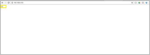
Figure 13-2 Output to the web browser
Integrating Bluetooth
Bluetooth is another wireless protocol we will examine. Bluetooth can replace wired communication between electronic devices with the attributes of low-power consumption and low cost. These traits make it lucrative for the embedded systems designer, since they go hand in hand with general embedded development.
A few years ago, it would have been very expensive to add Bluetooth connectivity to your system, because the modules available to the average developer were relatively expensive. Thanks to its popularity, the cost of adding Bluetooth connectivity to a project has rapidly declined.
The primary reason for this is due to the creation of low-cost Bluetooth modules by companies and manufacturers in the Chinese market. One such low-cost module is the HC05 Bluetooth module, shown in Figure 13-3.
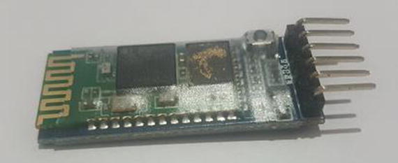
Figure 13-3 HC05 Bluetooth module
Using the HC05 Bluetooth Module
Using the HC05 is very simple. You simply connect the RX and TX pins of the module to the microcontroller through a logic-level converter. The Vcc and GND pins of the HC05 are connected to 5v and GND, respectively.
AT Mode
It is possible to place the HC05 in AT mode by pressing the small button on the module while it is powering on. Older versions of the modules enter the AT mode in a different way; therefore, I recommend you check the method that works for your particular module. Note that the baud rate for AT mode is 38400. Table 13-2 shows some AT commands for your module.
Table 13-2 Some HC05 AT Commands
Command | Function |
|---|---|
AT | Checks to ensure module is working. |
AT+VERSION? | Gets version. |
AT+ORGL | Restores to original state. |
AT+NAME=“MYNAME” | Sets device name. |
AT+UART | Gets UART configuration. |
AT+PSWD=“1234” | Sets password. |
Communicating via Bluetooth
The code for receiving commands for the HC05 is very simple. We will use this code to toggle an LED. When the ONPR command is sent to the module, the microcontroller turns the LED on. When OFFPR is sent to the module, the microcontroller turns the LED off. We will use the C needle in a haystack command, called strstr, to search the received command for ON or OFF.
The commands can be sent from a PC or a mobile device. On a PC or Android, when pairing the device, enter the default passcode 1234. On a PC, the device shows up as a COM port. I recommend the Termite program by CompuPhase to communicate via Bluetooth. On Android, there are a lot of Bluetooth terminals; however, I recommend an app named Bluetooth Terminal HC05, which works quite well and has preset buttons to make things simple. This module does not work with iOS.
Listing 13-2 provides the code.
Listing 13-2 Bluetooth Control Source
/** File: Main.c* Author: Armstrong Subero* PIC: 16F1717 w/Int OSC @ 16MHz, 5v* Program: I19_Bluetooth_HC05* Compiler: XC8 (v1.41, MPLAX X v3.61)* Program Version: 1.0*** Program Description: This Program Allows PIC16F1717 to communicate via*** Hardware Description: A HC-06 is connected to the PIC16F1717 as follows:** RX->RB3* TX->RB2** Created May 15th, 2017, 5:00 PM*//********************************************************************************Includes and defines******************************************************************************/#include "16F1717_Internal.h"#include "EUSART.h"#include <string.h>#define LED LATDbits.LATD1/******************************************************************************** Function: void initMain()** Returns: Nothing** Description: Contains initializations for main** Usage: initMain()******************************************************************************/void initMain(){// Run at 16 MHzinternal_16();// Set PIN D1 as outputTRISDbits.TRISD1 = 0;// Turn off LEDLATDbits.LATD1 = 0;// Set up PORTDTRISD = 0;ANSELD = 0;// Set up pins for EUSARTTRISBbits.TRISB2 = 0;ANSELBbits.ANSB2 = 0;TRISBbits.TRISB3 = 1;ANSELBbits.ANSB3 = 0;/////////////////////// Set up EUSART////////////////////PPSLOCK = 0x55;PPSLOCK = 0xAA;PPSLOCKbits.PPSLOCKED = 0x00; // unlock PPSRB2PPSbits.RB2PPS = 0x14; //RB2->EUSART:TX;RXPPSbits.RXPPS = 0x0B; //RB3->EUSART:RX;PPSLOCK = 0x55;PPSLOCK = 0xAA;PPSLOCKbits.PPSLOCKED = 0x01; // lock PPS}/******************************************************************************** Function: Main** Returns: Nothing** Description: Program entry point******************************************************************************/void main(void) {initMain();// Initialize EUSART module with 9600 baudEUSART_Initialize(9600);char buf[20];char* ON;char* OFF;while(1){// Send start so we'll know it's workingEUSART_Write_Text("Start");// Read UART messagesEUSART_Read_Text(buf, 4);// Test received stringON = strstr(buf, "ON");OFF = strstr(buf, "OFF");// If ON string, turn LED onif (ON){EUSART_Write_Text("LED ON");LED = 1;}// If OFF string, turn LED offelse if(OFF){EUSART_Write_Text("LED OFF");LED = 0;}}return;}
Conclusion
This chapter looked at using Bluetooth and Wi-Fi and using the PIC® microcontroller with the ESP8266. Bluetooth and Wi-Fi are arguably two of the most important wireless protocols available today. The information presented in this chapter was just enough so that you will be able to add these protocols to your own systems.