In this chapter, we look at building two projects using the PIC® microcontroller. The first is a classic microcontroller project involving a temperature controlled fan. The second project shows how far microcontroller technology has progressed and what is now possible with 8-bit bare metal systems by building a simple touch screen clock, a project that a few years ago would have required a 32-bit microcontroller.
Project: Temperature Controlled Fan
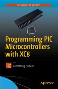
The first project involves building a temperature controlled fan. The LM34 temperature sensor output is converted to Celsius values, and when a particular threshold voltage is reached, the microcontroller turns on the fan. Once the temperature is within the normal values, the string "Temp OK" is displayed on the OLED. When the temperature crosses a certain value, the string "Warning!!" is displayed on the OLED.
Figure 15-1 shows the schematics of the temperature controlled fan.
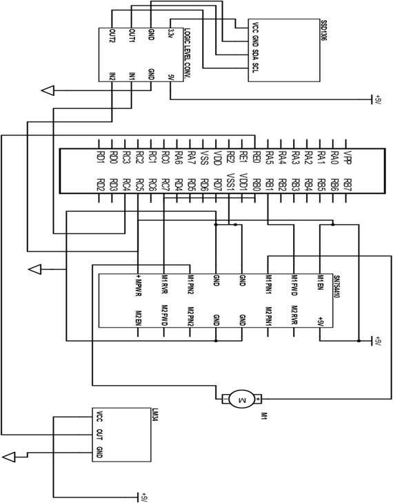
Figure 15-1 Temperature controlled fan schematics
Listing 15-1 shows the main code for the temperature controlled fan.
Listing 15-1 Temperature Controlled Fan
/** File: Main.c* Author: Armstrong Subero* PIC: 16F1717 w/Internal OSC @ 16MHz, 5v* Program: P04_Temp_Fan* Compiler: XC8 (v1.41, MPLAX X v3.55)* Program Version: 1.0** Program Description: This project builds a temperature controlled fan. When* the temperature rises above 35 Celsius a fan turns on* until the temperature drops to 35 Celsius or below.** Hardware Description: A generic brushed hobby DC motor is connected to the* SN754410 as per standard connections. The PWM signals* are emanating from RB0 and RB1. The LM34 temperature* sensor is connected to PIN RE0 and an SSD1306 based* OLED is connected as per header file.*** Created April 18th, 2017, 4:36 PM*//********************************************************************************Includes and defines******************************************************************************/#include "16F1717_Internal.h"#include "I2C.h"#include "oled.h"/******************************************************************************** Function: void initMain()** Returns: Nothing** Description: Contains initializations for main** Usage: initMain()******************************************************************************/void initMain(){// Run at 16 MHzinternal_16();///////////////////////// Configure PWM Ports///////////////////////// Set PIN B0 as outputTRISBbits.TRISB0 = 0;// Set PIN B1 as outputTRISBbits.TRISB1 = 0;// Turn off analog on PORTBANSELB = 0;/////////////////////// Configure Timer6/////////////////////// Select PWM timer as Timer6 for CCP1 and CCP2CCPTMRSbits.C1TSEL = 0b10;CCPTMRSbits.C2TSEL = 0b10;// Enable timer Increments every 250 ns (16MHz clock) 1000/(16/4)// Period = 256 x 0.25 us = 64 us// Crystal Frequency//PWM Freq = -----------------------------------------//(PRX + 1) * (TimerX Prescaler) * 4//PWM Frequency = 16 000 000 / 256 * 1 * 4//PWM Frequency = 15.625 kHz// Prescale = 1T6CONbits.T6CKPS = 0b00;// Enable Timer6T6CONbits.TMR6ON = 1;// Set timer periodPR6 = 255;//////////////////////////// Configure PWM/////////////////////////// Configure CCP1// LSB's of PWM duty cycle = 00CCP1CONbits.DC1B = 00;// Select PWM modeCCP1CONbits.CCP1M = 0b1100;// Configure CCP2// LSB's of PWM duty cycle = 00CCP2CONbits.DC2B = 00;// Select PWM modeCCP2CONbits.CCP2M = 0b1100;/////////////////////// Setup I2C//////////////////// Setup pins for I2CANSELCbits.ANSC4 = 0;ANSELCbits.ANSC5 = 0;TRISCbits.TRISC4 = 1;TRISCbits.TRISC5 = 1;//////////////////////////////// Configure PPS/////////////////////////////PPSLOCK = 0x55;PPSLOCK = 0xAA;PPSLOCKbits.PPSLOCKED = 0x00; // unlock PPS// Set RB0 to PWM1RB0PPSbits.RB0PPS = 0b01100;// Set RB1 to PWM2RB1PPSbits.RB1PPS = 0b01101;RC4PPSbits.RC4PPS =0x0011; //RC4->MSSP:SDA;SSPDATPPSbits.SSPDATPPS =0x0014; //RC4->MSSP:SDA;SSPCLKPPSbits.SSPCLKPPS =0x0015; //RC5->MSSP:SCL;RC5PPSbits.RC5PPS =0x0010; //RC5->MSSP:SCL;PPSLOCK = 0x55;PPSLOCK = 0xAA;PPSLOCKbits.PPSLOCKED = 0x01; // lock PPS////////////////////// Configure ADC///////////////////// Fosc/32 ADC conversion time is 2.0 usADCON1bits.ADCS = 0b010;// Right justifiedADCON1bits.ADFM = 1;// Vref- is VssADCON1bits.ADNREF = 0;// Vref+ is VddADCON1bits.ADPREF = 0b00;// Set input channel to AN0ADCON0bits.CHS = 0x05;// Zero ADRESL and ADRESHADRESL = 0;ADRESH = 0;// ADC Input channel PIN E0ANSELEbits.ANSE0 = 1;}/******************************************************************************** Function: Main** Returns: Nothing** Description: Program entry point******************************************************************************/void main(void) {initMain();// Initialize I2CI2C_Init();__delay_ms(500);// Initialize OLEDOLED_Init();__delay_ms(1000);// clear OLEDOLED_Clear();// result to store ADC conversionfloat result;// variables for conversionfloat conversion10;float farenheit;float celsius;// PWM OffCCPR1L = 0;CCPR2L = 0;OLED_YX(0, 0);OLED_Write_String("Init");while(1){// Turn ADC onADCON0bits.ADON = 1;// Sample CH0__delay_us(10);ADCON0bits.GO = 1;while (ADCON0bits.GO_nDONE);// Store ADC resultresult = ((ADRESH<<8)+ADRESL);// 10 bit conversionconversion10 = (result * 5000)/1024 ;// to Fahrenheitfarenheit = conversion10 / 10;// to Celsiuscelsius = (farenheit - 32) * 5/9;// Display temperatureOLED_YX(1, 0);OLED_Write_Integer((int)celsius);// Update every second__delay_ms(2000);// If temperature is more than 35C turn on fanif ((int)celsius > 35){// ForwardCCPR1L = 127;CCPR2L = 0;// clear OLEDOLED_Clear();OLED_YX(0, 0);OLED_Write_String("Warning!!");}// If less turn off fanelse{OLED_YX(0, 0);OLED_Write_String("Temp OK");CCPR1L =0;CCPR2L =0;}}return;}
Project: Touch Screen Clock
In this section, we make a basic touch screen clock. We use the DS1302 timekeeper. Though there are many modern Real Time Clock Calendar (RTCC) ICs on the market, the beauty of the DS1302 is that it uses a non-standard protocol. The DS1302 uses a protocol called the “three wire interface”. This is not necessarily a bad thing, because if your I2C and SPI bus are occupied, you can used this RTCC on any available pin.
We will use the Nextion 2.4 touch LCD as the display. The interrupt on the PIC® will update the time on the display every five seconds. This is acceptable as it gives the microcontroller sufficient time for the touch screen to react to other user events.
The clock consists of two screens. The first screen will display the time and date to the user. The second screen will allow the user to set the time and date.
Let’s create the first screen , as shown in Figure 15-2.

Figure 15-2 Screen 1
Now create the second one, as shown in Figure 15-3.
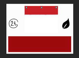
Figure 15-3 Screen 2
Open the Nextion Editor and add touch hotspots, as shown on screen 1 in Figure 15-4.
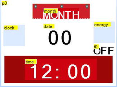
Figure 15-4 Nextion Editor on screen 1
The clock hotspot opens the second page. The green (leaf) icon sends the text enerpressed and the text under it keeps the default label t0. The other text labels are added and renamed month, date, and time. Feel free to customize the layout according to your needs.
Use the editor to make screen 2 look like Figure 15-5.
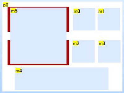
Figure 15-5 Nextion Editor Screen 2
The second screen has text views t0, t1, t2, and t3, representing the hours, minutes, date, and month. Each is overlaid by hotspots that send m0, m1, m2, and m3, which send hourpressed, minspressed, datepressed, and monthpressed, respectively. The hotspot at the bottom (m4) is used to set the current time. It is very important and sends the text setppressed (not a typo; be sure to use the double p).
Figure 15-6 shows the schematics for this project.

Figure 15-6 Clock schematics
This project contains a lot of code. Let’s break it down. The first thing we need to add is a header file for bool support, as shown in Listing 15-2.
Listing 15-2 Bool Support
/** File: bool_support.h* Author: Armstrong Subero* PIC: 16F1717 w/X OSC @ 16MHz, 5v* Program: Header file to setup PIC16F1717 I2C* Compiler: XC8 (v1.35, MPLAX X v3.10)* Program Version 1.0** Program Description: This program header will allow addition of simple bool* support to XC8** Created on March 10th, 2017, 8:00 PM*/////////////////////////////// Bool support///////////////////////////typedef unsigned char bool;#define true 1#define false 0// boolean for current statebool on = false;
Next, we add a header file for setup, as shown in Listing 15-3. This is necessary. Due to the size of the program, we will separate the initialization from the main file.
Listing 15-3 Setup Header
/** File: setup.h* Author: Armstrong Subero* PIC: 16F1717 w/X OSC @ 16MHz, 5v* Program: Header file to setup PIC16F1717 I2C* Compiler: XC8 (v1.40, MPLAX X v3.55)* Program Version 1.0** Program Description: This program header will allow setup of SSD 1306 OLEDs** Created on April 21st, 2017, 2:25 PM*/#include "16F1717_Internal.h"void initMain();
The next step is to create a header file for the touch screen, as shown in Listing 15-4.
Listing 15-4 Touch Screen Header
/** File: touchscreen.h* Author: Armstrong Subero* PIC: 16F1717 w/X OSC @ 16MHz, 5v* Program: Header file to setup PIC16F1717 I2C* Compiler: XC8 (v1.40, MPLAX X v3.55)* Program Version 1.0** Program Description: This program header provide function prototypes for* sending commands to a Nextion Touch Display** Created on April 21st, 2017, 2:25 PM*/#include "16F1717_Internal.h"#include <string.h>// Function prototypesvoid touchscreen_command(char* string);void touchscreen_data(char* cmd, char* string2);
The RTCC header (see Listing 15-5) and source (see Listing 15-6) are created. Notice that the three-wire interface can be used on any pin. The DS1302 provides its data in BCD format. It is necessary therefore to create functions to allow the conversion to and from that format.
Listing 15-5 DS1302 Header
/** File: ds1302.h* Author: Armstrong Subero* PIC: 16F1717 w/X OSC @ 16MHz, 5v* Program: Header file to setup PIC16F1717 I2C* Compiler: XC8 (v1.41, MPLAX X v3.55)* Program Version 1.0** Program Description: This program header allows the control of a DS1302* time keeper chip** Created on April 18th, 2017, 11:40 PM*/#include "16F1717_Internal.h"#define CE RD0#define SCLK RD1#define IO RD2#define Data_Tris TRISD2typedef unsigned char byte;void DS1302_Reset();void DS1302_WriteByte(unsigned char W_Byte);unsigned char DS1302_ReadByte();void DS1302_Initialize(byte sec, byte min, byte hr, byte day, byte date, byte mth, byte year);unsigned char get_bcd(unsigned char data);unsigned char get_dec(byte var);
Listing 15-6 DS1302 Source
/** File: ds1302.c* Author: Armstrong SuberoPIC: 16F1717 w/Int OSC @ 16MHz, 5v* Program: Library file for ds1302 RTCC* Compiler: XC8 (v1.38, MPLAX X v3.40)* Program Version: 1.1**Added additional comments** Program Description: This Library allows you to control the ds1302** Created on April 18th, 2017, 11:40 PM*/#include "ds1302.h"/******************************************************************************** Function:void DS1302_Reset()** Returns: Nothing** Description: Resets the DS1302*******************************************************************************/void DS1302_Reset(){SCLK = 0;CE = 0;CE = 1;}/******************************************************************************** Function: unsigned char DS1302_WriteByte(unsigned char W_Byte)** Returns: Nothing** Description: Writes a byte of data into the DS1302*******************************************************************************/void DS1302_WriteByte(unsigned char W_Byte){unsigned char i;for(i = 0; i < 8; ++i){IO = 0;if(W_Byte & 0x01){IO = 1; /* set port pin high to read data */}SCLK = 0;SCLK = 1;W_Byte >>= 1;}}/******************************************************************************** Function: unsigned char DS1302_ReadByte()** Returns: Nothing** Description: Reads a byte of data from the DS1302*******************************************************************************/unsigned char DS1302_ReadByte(){unsigned char i;unsigned char R_Byte;unsigned char TmpByte;R_Byte = 0x00;Data_Tris = 1;IO = 1;for(i=0; i<8; ++i){SCLK = 1;SCLK = 0;TmpByte = (unsigned char)IO;TmpByte <<= 7;R_Byte >>= 1;R_Byte |= TmpByte;}Data_Tris = 0;return R_Byte;}/******************************************************************************** Function: void DS1302_Initialize(byte sec, byte min, byte hr, byte day, bytedate,byte mth, byte year)** Returns: Nothing** Description: Initializes the DS1302 with time/date specified by user*******************************************************************************/void DS1302_Initialize(byte sec, byte min, byte hr, byte day, byte date,byte mth, byte year){byte sec1 = get_bcd(sec);byte min1 = get_bcd(min);byte hr1 = get_bcd(hr);byte day1 = get_bcd(day);byte date1 = get_bcd(date);byte mth1 = get_bcd(mth);byte year1 = get_bcd(year);DS1302_Reset();DS1302_WriteByte(0x8e); /* control register */DS1302_WriteByte(0); /* disable write protect */DS1302_Reset();DS1302_WriteByte(0x90); /* trickle charger register */DS1302_WriteByte(0xab);/* enable, 2 diodes, 8K resistor */DS1302_Reset();DS1302_WriteByte(0xbe);/* clock burst write (eight registers) */DS1302_WriteByte(sec1);DS1302_WriteByte(min1);DS1302_WriteByte(hr1);DS1302_WriteByte(date1);DS1302_WriteByte(mth1);DS1302_WriteByte(day1);DS1302_WriteByte(year1);DS1302_WriteByte(0); /* must write control register in burst mode */DS1302_Reset();}/******************************************************************************** Function: unsigned char get_bcd(unsigned char data)** Returns: number in BCD format for RTCC** Description: Converts decimal time into BCD format*******************************************************************************/unsigned char get_bcd(unsigned char data){unsigned char nibh;unsigned char nibl;nibh=data/10;nibl=data-(nibh*10);return((nibh<<4)|nibl);}unsigned char get_dec(byte var){unsigned char var2;var2 = (var >> 4) * 10;var2 += (var & 15);return var2;}
We also need to create source files for the touch screen (see Listing 15-7) and the setup headers (see Listing 15-8) we declared earlier.
Listing 15-7 Touch Screen Source
/** File: touchscreen.c* Author: Armstrong Subero* PIC: 16F1717 w/Int OSC @ 16MHz, 5v* Program: Library file for Nextion Touchscreen* Compiler: XC8 (v1.41, MPLAX X v3.55)* Program Version: 1.0** Program Description: This Library allows you to send commands to the Nextion* touchscreen** Created on April 21st, 2017, 2:30 PM*/#include "touchscreen.h"#include "EUSART.h"/*Send commands to Touchscreen*/void touchscreen_command(char* string){EUSART_Write_Text(string);EUSART_Write(0xFF);EUSART_Write(0xFF);EUSART_Write(0xFF);__delay_ms(1000);}void touchscreen_data(char* cmd, char* string2){EUSART_Write_Text(cmd);EUSART_Write_Text(string2);EUSART_Write(0xFF);EUSART_Write(0xFF);EUSART_Write(0xFF);__delay_ms(100);}
Listing 15-8 Setup Source
/** File: setup.c* Author: Armstrong Subero* PIC: 16F1717 w/Int OSC @ 16MHz, 5v* Program: Library file for Nextion Touchscreen* Compiler: XC8 (v1.41, MPLAX X v3.55)* Program Version: 1.0** Program Description: This Library allows you to setup for the clock** Created on April 21st, 2017, 2:30 PM*/#include "setup.h"#include "ds1302.h"#include "oled.h"#include "EUSART.h"#include "touchscreen.h"/******************************************************************************** Function: void initMain()** Returns: Nothing** Description: Contains initializations for main** Usage: initMain()******************************************************************************/void initMain(){// Run at 16 MHzinternal_16();// Setup pins for EUSARTTRISBbits.TRISB2 = 0;ANSELBbits.ANSB2 = 0;TRISBbits.TRISB3 = 1;ANSELBbits.ANSB3 = 0;/////////////////////// Setup Serial////////////////////// Setup pins for I2CANSELCbits.ANSC4 = 0;ANSELCbits.ANSC5 = 0;TRISCbits.TRISC4 = 1;TRISCbits.TRISC5 = 1;PPSLOCK = 0x55;PPSLOCK = 0xAA;PPSLOCKbits.PPSLOCKED = 0x00; // unlock PPSRC4PPSbits.RC4PPS = 0x0011; //RC4->MSSP:SDA;SSPDATPPSbits.SSPDATPPS =0x0014; //RC4->MSSP:SDA;SSPCLKPPSbits.SSPCLKPPS =0x0015; //RC5->MSSP:SCL;RC5PPSbits.RC5PPS = 0x0010; //RC5->MSSP:SCL;RB2PPSbits.RB2PPS = 0x14; //RB2->EUSART:TX;RXPPSbits.RXPPS = 0x0B; //RB3->EUSART:RX;PPSLOCK = 0x55;PPSLOCK = 0xAA;PPSLOCKbits.PPSLOCKED = 0x01; // lock PPS// Setup RTCC pinsTRISD = 0;ANSELD = 0;// Initialize I2CI2C_Init();__delay_ms(500);// Initialize OLEDOLED_Init();__delay_ms(500);// Dim TouchscreenOLED_YX(0, 0);OLED_Write_String("Init");__delay_ms(1000);// clear OLEDOLED_Clear();__delay_ms(500);// Initial time and datebyte sec = 51;byte min = 59;byte hr = 23;byte day = 2;byte date = 30;byte month = 4;byte year = 17;// Initialize DS1302DS1302_Initialize(sec, min, hr, day, date, month, year);//Initialize EUSART module with 9600 baudEUSART_Initialize(9600);__delay_ms(2000);// clear OLEDOLED_Clear();///////////////////////// Configure Timer0//////////////////////// Select timer modeOPTION_REGbits.TMR0CS = 0;// Assign Prescaler to TIMER0OPTION_REGbits.PSA = 0;// Set Prescaler to 256OPTION_REGbits.PS = 0b111;// enable Timer0 interruptINTCONbits.TMR0IE = 1;// enable global interruptsei();}
Finally, we have the main code in Listing 15-9. The interrupt routine updates the display date and time every five seconds. There is a “green” function that lessens the brightness of the display. The main code is simply a series of checks of the buffer read from UART. If any of the string we want to be sent by the touch screen is detected, then the display is updated accordingly.
Listing 15-9 Main Code
/** File: Main.c* Author: Armstrong Subero* PIC: 16F1717 w/Int OSC @ 16MHz, 5v* Program: P05_Clock* Compiler: XC8 (v1.38, MPLAX X v3.40)* Program Version: 1.0*** Program Description: This Program creates a clock using the PIC17F1717* microcontroller and the DS1302. The display is* the intelligent Nextion 2.4 LCD. There are two screens* the main screen displays. The main screen displays the* time and date. The second screen allows the user to set* the current time and date.** Hardware Description: The DS1302 is connected to the microcontroller as* follows:** CE -> RD0* SCLK -> RD1* IO -> RD2*** Created April 21st, 2017, 7:11 PM*//********************************************************************************Includes and defines******************************************************************************/#include "16F1717_Internal.h"#include "I2C.h"#include "oled.h"#include "ds1302.h"#include "EUSART.h"#include "setup.h"#include "touchscreen.h"#include "bool_support.h"#include <string.h>// Variables for date and timeunsigned char yr1, mn1, date1, dy1, hr1, min1, sec1;unsigned char yr2, mn2, date2, dy2, hr2, hr3, min2, sec2;// Arrays for int to ascii conversionchar min_arr[8];char hr_arr[8];char dt_arr[5];char minute_arr[10];char hour_arr[10];char date_arr[10];char mth_arr[10];char month_arr[10];// Arrays to hold date, month and time stringchar time_string[10];char date_string[10];char hour_string[10];char min_string[10];char date1_string[10];char month_string[10];char mth_string[10];// String constants for commandsconst char screen_time[] = "time.txt=";const char screen_date[] = "date.txt=";const char screen_mth[] = "month.txt=";const char screen_hour[] = "t0.txt=";const char screen_mins[] = "t1.txt=";const char screen_date1[] = "t2.txt=";const char screen_month[] = "t3.txt=";// Array containing monthsconst char* months[] = {"MMM", "JAN", "FEB", "MAR", "APR", "MAY", "JUN","JUL", "AUG", "SEP", "OCT", "NOV", "DEC"};// buffer for UARTchar buf[50];// Variables to store values for min, hour, month and dateunsigned char x = 1;unsigned char y = 0;unsigned char m = 1;unsigned char d = 1;// energy efficient functionvoid green(char* buf);/******************************************************************************** Function: Main** Returns: Nothing** Description: Program entry point******************************************************************************/void main(void) {initMain();char* hour1;char* min1;char* date3;char* month1;char* set1;while(1){// Read EUSARTEUSART_Read_Text(buf, 11);// Check for if energy save enabledgreen(buf);//////////////////////////// Check buffer for each// string from display/////////////////////////hour1 = strstr(buf, "hour");min1 = strstr(buf, "mins");date3 = strstr(buf, "date");month1 = strstr(buf, "month");set1 = strstr(buf, "set");/////////////////////// If minute found////////////////////if (min1){// Convert date and time to stringsitoa( minute_arr, y, 10 );strcpy(min_string, """);// If less than 10 pad with a 0if (y < 10){strcat(min_string, "0");strcat(min_string, minute_arr);}// Else show min as iselse{strcat(min_string, minute_arr);}strcat(min_string, """);if (y < 59){y++;}else {y = 0;}// Write timetouchscreen_data(screen_mins, min_string);}/////////////////////// If hour found////////////////////if (hour1){// Convert date and time to stringsitoa( hour_arr, x, 10 );strcpy(hour_string, """);strcat(hour_string, hour_arr);strcat(hour_string, """);if (x < 12){x++;}else {x = 1;}// Write timetouchscreen_data(screen_hour, hour_string);}////////////////////// If date found///////////////////if(date3){// Convert date and time to stringsitoa( date_arr, d, 10 );strcpy(date1_string, """);strcat(date1_string, date_arr);strcat(date1_string, """);if (d < 31){d++;}else {d = 0;}// Write timetouchscreen_data(screen_date1, date1_string);}///////////////////// If month found///////////////////if(month1){// Convert date and time to stringsitoa( month_arr, m, 10 );strcpy(month_string, """);strcat(month_string, month_arr);strcat(month_string, """);if (m < 12){m++;}else {m = 1;}// Write timetouchscreen_data(screen_month, month_string);}///////////////////////// If user pressed set//////////////////////if (set1){// Initial time and datebyte sec = 00;byte min = y-1;byte hr = x-1;byte day = 2;byte date = d-1;byte month = m-1;byte year = 17;// Re-Initialize DS1302 with new valuesDS1302_Initialize(sec, min, hr, day, date, month, year);touchscreen_command("page 0");}}return;}/******************************************************************************** Function: void green (char* buf)*Returns: Nothing** Description: Enables or disables green feature of display******************************************************************************/void green(char* buf){char* green1;green1 = strstr(buf, "ener");if (green1 == NULL){return;}else{if (!on){touchscreen_command("t0.txt="ON"");__delay_ms(100);touchscreen_command("dim=30");__delay_ms(100);on = true;}else {touchscreen_command("t0.txt="OFF"");__delay_ms(100);touchscreen_command("dim=100");__delay_ms(100);on = false;}}}/******************************************************************************** Function: void interrupt isr(void)** Returns: Nothing** Description: Timer0 interrupt at a rate of approx. 5 seconds that updates* the time on the display******************************************************************************/void interrupt isr(void){// Start count at 0static int count = 0;// Reset flag after overflowINTCONbits.TMR0IF = 0;// Zero timerTMR0 = 0;// Increment countcount++;// Value = fclk / (4 * 256 * 256 * fout)//|-- Frequency out (in Hz)//|-- Prescaler value// Value = 16 000 000 / (262 144)// Value = 61.04 for 1 s// Therefore 305 for approx 5 secsif (count == 305){////////////////////////////// Read DS1302 clock burst////////////////////////////DS1302_Reset();DS1302_WriteByte(0xBF);sec1 = DS1302_ReadByte();min1 = DS1302_ReadByte();hr1 = DS1302_ReadByte();date1 = DS1302_ReadByte();mn1 = DS1302_ReadByte();dy1 = DS1302_ReadByte();yr1 = DS1302_ReadByte();DS1302_Reset();/////////////////////////// Convert all BCD data// to Decimal time format//////////////////////////// Yearyr2 = get_dec(yr1);// Monthmn2 = get_dec(mn1);// Datedate2 = get_dec(date1);// Hourhr2 = get_dec(hr1);// Minutemin2 = get_dec(min1);// Secondssec2 = get_dec(sec1);///////////////////////////// Convert 24 hr to 12 hr// format///////////////////////////if (hr2 <= 12 && hr2 > 0){hr3 = hr2;}else if (hr2 >= 13 && hr2 < 24){hr3 = (hr2-12);}else {hr3 = 12;}////////////////////////////// Convert date and time// to strings///////////////////////////itoa( min_arr, min2, 10 );itoa( hr_arr, hr3, 10 );itoa( dt_arr, date2, 10);///////////////////////////// Create date string//////////////////////////strcpy(date_string, """);strcat(date_string, dt_arr);strcat(date_string, """);///////////////////////////// Create month string//////////////////////////strcpy(mth_string, """);strcat(mth_string, months[mn2]);strcat(mth_string, """);//////////////////////////// Create time string//////////////////////////strcpy(time_string, """);strcat(time_string, hr_arr);strcat(time_string, ":");// If less than 10 pad with a 0if (min2 < 10){strcat(time_string, "0");strcat(time_string, min_arr);}// Else show min as iselse{strcat(time_string, min_arr);}strcat(time_string, """);// Write timetouchscreen_data(screen_time, time_string);// Write monthtouchscreen_data(screen_mth, mth_string);// Write datetouchscreen_data(screen_date, date_string);// Reset countcount = 0;}else {/ No need to do anything}}
The final results are shown in Figures 15-7 and 15-8.
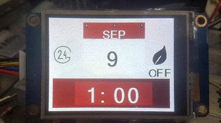
Figure 15-7 Screen 1
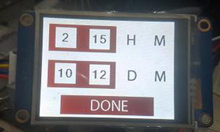
Figure 15-8 Screen 2
Conclusion
At last, the finale. This chapter we looked at building two projects using the PIC® microcontroller. It first covered building a simple temperature controlled fan followed by a touch screen clock.
You have now reached the end of this book. I hope you learned enough that you can successfully build your own projects. Happy tinkering!