Electronics
The difference between embedded systems designers and software engineers or IT technicians is the in-depth knowledge of the hardware that embedded designers possess. Embedded designers must have knowledge of electronics to effectively design embedded systems. We must remember, above everything else, that computers are simply complex electronic devices and microcontrollers are simply miniature computers. Resistors, capacitors, diodes, and transistors are some of the building blocks of computer hardware. In order to understand these more complex devices, it is important to understand the basic electronic components from which these devices are built.
Resistors
A resistor is used in electronics to impose resistance into circuits. Resistors are rated by the amount of ohms, which is essentially a measure of the amount of resistance they provide.
Resistors are used to reduce the flow of current in a circuit and to reduce the voltage. They are also used to divide voltages and pull up I/O lines.
Resistors come in a variety of packages, including an axial package, radial package, surface mount package, and a type of Single Inline Package (SIL) called a resistor array. Resistors are passive components and are one of the simplest types of devices you’ll encounter.
Resistors have wattage ratings that must not be exceeded. Typically, ratings range from 1/8 watt to 2 watts. 1/4-watt resistors are the most common ones used in embedded systems design. The commonly found surface mount variety typically have a rating of 1/16 and 1/10 watts. However, it is best to consult the datasheet for the resistor you are planning to use.
A datasheet is a document that tells you a little bit about the technical specifications of a product. For example, a resistor’s datasheet includes electrical characteristics such as tolerance and operating curve, as well as the dimensions of the part. This information is very useful when you are designing a printed circuit board or PCB. For the microcontroller, a datasheet includes the block diagram (as you’ll see in a later chapter) as well as a lot of other useful information. Datasheets are your friends and you should always keep them handy. You can get the datasheets from the manufacturer’s web site. Some component suppliers, such as Digi-Key and Mouser, also list the datasheets on their product pages.
Resistance is measured in ohms, as shown in Figure 3-1.

Figure 3-1 Ohm symbol
Most resistors have four bands. The first two bands are the most significant digits. The third bands tells you of the power of 10 you have to multiply by and the final band is the tolerance of the resistor. Usually the tolerance can be ignored; however, for some applications the tolerance must be within a very narrow range.
Surface mount resistors typically either use the E24 or E96 type markings. The E24 has three numbers. The first two numbers are the significant digits and the third is the index of base 10 to multiply by. For example, a resistor marked 104 would be 10x10ˆ4, which is 100 kiloohms. Figure 3-2 shows the resistor schematic symbol and Figure 3-3 shows an actual resistor.
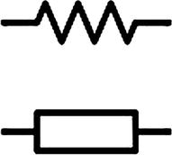
Figure 3-2 Resistor schematic symbol
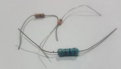
Figure 3-3 Resistor
Potentiometer
A potentiometer is an electronic component used to vary the amount of resistance in a circuit. The potentiometer is also known as a “pot” and contains three terminals. A pot is nothing more than a voltage divider that the user can adjust. A rheostat is another device you may encounter, and it is simply an adjustable resistor. The two-axis joystick commonly found in game controllers and volume adjust buttons are common real-world applications of potentiometers. Figure 3-4 shows the potentiometer schematic symbol and Figure 3-5 shows an actual potentiometer.
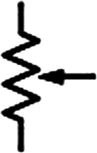
Figure 3-4 Potentiometer schematic symbol
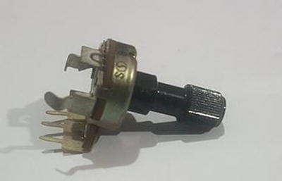
Figure 3-5 Potentiometer
Digital Potentiometer
A digital potentiometer or digipot is a digital version of a potentiometer. Electronically speaking, it performs the same functions as a potentiometer. The advantage of the digipot is that microcontrollers can adjust their resistance using some digital interface protocol, such as SPI or I2C, using software.
Since they can be controlled via software unlike their mechanical counterparts, it is possible to adjust the value in ways other than a linear fashion (typically in a logarithmic fashion). This gives digipots additional applications such as scaling and trimming of analog signals. The digipot has a different appearance than a regular potentiometer and they are packaged to look just like any other IC. The MCP 4131 digipot that we’ll be using in our projects is shown in Figure 3-6. Figure 3-7 shows the digipot schematic symbol.
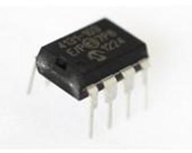
Figure 3-6 MCP 4131
Figure 3-7 Digipot schematic symbol
Photoresistor
A photoresistor, also known as a light dependent resistor (LDR) or photocell , is a type of resistor where the resistance changes with light intensity. Figure 3-8 shows the photoresistor schematic symbol and Figure 3-9 shows an actual photoresistor.
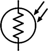
Figure 3-8 Photoresistor schematic symbol
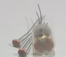
Figure 3-9 Photoresistor
Capacitor
Capacitors are used to store electrical energy in an electronic circuit (see Figure 3-12). Capacitors come in axial, radial, and SMT packages. They consist of two metal plates separated by an insulator, called the dielectric. This dielectric material is made of many materials, including paper, ceramic, plastic, and even air. Capacitance is measured in Farads (F), although microfarads and picofarads are the commonly used units of measurement in everyday usage.
The type of dielectric influences the properties of the capacitor and determines if the capacitor is polarized or non-polarized. Figure 3-10 shows the polarized cap schematic symbols and Figure 3-11 shows the non-polarized cap schematic symbols.
The most commonly encountered capacitor is the electrolytic capacitor. This is because they store a relatively large capacitance relative to their size. They are polarized and care must be taken not to connect them backward. They come in two varieties—Tantalum and Aluminum. Aluminum capacitors are easily recognizable since they usually come in cylindrical tin cans. Tantalum capacitors have a higher capacitance to weight ratio than aluminum capacitors and are usually more expensive.
Ceramic capacitors are another commonly encountered type of capacitor in embedded system design. Unlike electrolytic capacitors, they have the advantage of not being polarized. However, they have a lower capacitance.
The most prominent use of capacitors in the embedded space is in filtering the output of power supplies. Many microcontrollers require filtering capacitors on their power pins. Decoupling capacitors act as a temporary voltage source for microcontrollers and are very important in suppressing high-frequency noise on the power supply. When used in this way, decoupling capacitors are also known as bypass capacitors since they bypass the power supply. It is important to consult the datasheet to determine the value of bypass capacitors you should use.
There are many occasions where many intermittent problems in your circuits can be traced to having a noisy power supply. A power supply is noisy when there are ripples on the power rail. These ripples are essentially fluctuations in the supply voltage. If you look at your DC output from a power supply with an oscilloscope, you will notice these ripples. If they are too large, they can cause a lot of problems in your circuit and may lead to undesired operations and, in some cases, damages to the IC and other sensitive electronics.
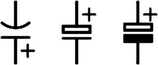
Figure 3-10 Polarized cap schematic symbols
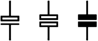
Figure 3-11 Non-polarized cap schematic symbols
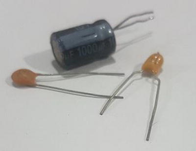
Figure 3-12 Some capacitors
Inductor
Inductors are used to resist changes in electric current flowing through it (see Figure 3-14). The most common use of inductors is in filters as an inductor passes low frequency signals and resists high frequency ones.
The Henry (H) is used to measure inductance. The nanohenry, microhenry, and millihenry are the most commonly encountered units. Figure 3-13 shows the inductor schematic symbols.
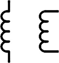
Figure 3-13 Inductor schematic symbols
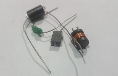
Figure 3-14 Inductor
Transformers
A transformer is a device used to step up or step down voltages in electronic devices.
Transformers require an alternating current to operate. Figure 3-15 shows the transformer schematic symbols and Figure 3-16 shows an actual transformer.
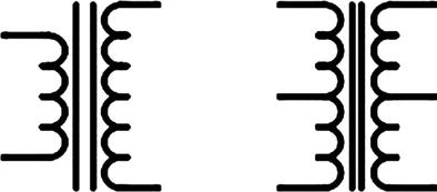
Figure 3-15 Transformer schematic symbols
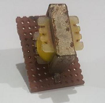
Figure 3-16 Transformer
Diode
A diode is a device used to allow current to flow in a particular direction. When the diode is forward biased, current can flow. When the diode is reverse biased, current cannot flow. If a certain voltage is applied in the reverse direction, the diode will break down and allow current to flow in the opposite direction. Diodes are extremely important in embedded devices, as they are imperative to suppressing voltage spikes that can be present when driving inductive loads. Figure 3-17 shows the diode schematic symbol .

Figure 3-17 Diode schematic symbol
Zener Diode
Zener diodes are devices that operate in the breakdown voltage region and are used for voltage stabilization, voltage regulation, and as a voltage reference. Figure 3-18 shows the Zener diode schematic symbol. In Figure 3-19, you see the Zener diode (glass body) under a regular diode (black body). You must be aware that regular diodes may also have glass bodies.
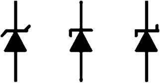
Figure 3-18 Zener diode schematic symbol
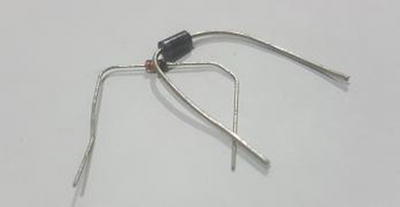
Figure 3-19 Zener and regular diode
Light Emitting Diode
A Light Emitting Diode (LED) is a type of diode that emits light when a voltage is applied to it. Diodes come in a variety of colors and sizes. The types encountered are infrared, red, orange, yellow, green, blue, violet, purple, pink, ultraviolet, and white. There are also bi-color LEDs and RGB LEDs. There are surface-mount LEDs and of course standard 3mm and 5mm LEDs that are used in most projects. Seven segment, sixteen segment, and dot-matrix LEDs are also used in a variety of projects. Figure 3-20 shows the LED schematic symbols and Figure 3-21 shows an LED.
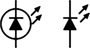
Figure 3-20 LED schematic symbols
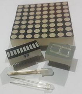
Figure 3-21 LEDs
Laser Diode
The laser diode (see Figure 3-22) is another type of diode common in embedded systems. They are low cost and weigh very little, making them very useful for a variety of projects.
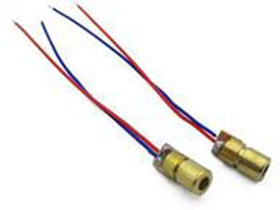
Figure 3-22 Laser diode
Transistors
Transistors are arguably the most revolutionary devices ever invented. Modern devices would not be possible without the transistor. Transistors are mainly used for switching and rectification in electronic circuits. Transistors come in a variety of types, which will be briefly discussed in the following sections.
Bipolar Junction Transistors
The Bipolar Junction Transistor (BJT) comes in two varieties and may be either NPN- or PNP-based. These names come from the designation of the semiconductor material of which it is constructed. A semiconductor with extra electrons is of the N-type variety and one with fewer electrons is of the P-type variety. If that semiconductor is stacked in the order of N-type, P-type, N-type, then you get the NPN variety. Similarly, if it is stacked P-type, N-type, P-type, then the PNP variety is created.
As mentioned, they come in two varieties—NPN based and PNP based. These two types of transistors can be differentiated by the direction of the arrow on the emitter pin in schematic drawings. The PNP type transistor has the arrow pointing inward, while the NPN variety has the arrow pointing outward (see Figure 3-23).
Transistors are three pin devices—the collector (C), the base (B), and the emitter (E). The transistor is used extensively for signal amplifying and electronic switching. When used for amplification, the transistors convert a low power signal into one of higher power. The name given to the type of transistor amplifier is determined by the pin into which the signal to be amplified enters and exits.
The most common type of amplifier is the common-emitter type amplifier. In this mode, the emitter is tied to the ground, the signal entry point is the base, and the exit point is the collector. This type of amplifier is commonly used to amplify audio signals since it performs voltage amplification.
The common-collector is the other type of amplifier configuration of the transistor. In this mode, the collector is connected to the ground and the signal enters the base and exits the emitter. This type of amplifier is used for voltage buffering and current amplification.
The final type of amplifier we will look at is the common-base configuration, which is rarely used in practice. The base is connected to the ground with the emitter as the input and the collector as the output. It has applications as a current buffer. Figure 3-23 shows the transistor schematic symbols and Figure 3-24 shows some common NPN transistors.
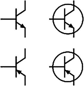
Figure 3-23 Transistor schematic symbols
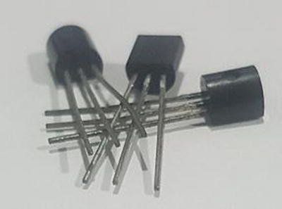
Figure 3-24 Commonly used NPN transistors
Darlington Transistor
A Darlington transistor consists of two transistors connected in such a manner that the current output of the first transistor is further amplified by the second one. The Darlington pair uses two PNP or two NPN transistors and a complementary Darlington uses one NPN and one PNP transistor.
They act as a single transistor with a high current gain. This property is important in embedded applications, as in microcontroller based circuits, they can use a small amount of current from the microcontroller to run a larger load. This gives them many uses, such as display drivers and control of motors and solenoids.
Another Darlington Transistor that you may have to use is the Photodarlington transistor. This transistor consists of two transistors just like a regular Darlington. However, they differ in that the first transistor acts as a photodetector and its emitter is coupled with the base of the second transistor. Figure 3-25 shows the Darlington transistor schematic symbols.
The Photodarlington has a high gain but is slower than ordinary phototransistors.
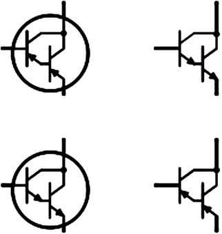
Figure 3-25 Darlington transistor schematic symbols
The ULN2003, which will be used to drive small stepper motors in this book, consists of an array of Darlington transistors. Figure 3-26 shows the ULN2003 schematic symbol.
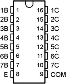
Figure 3-26 ULN2003 schematic symbol
Field Effect Transistor
Field Effect Transistors or FETs can be either N-channel or P-channel based and operate in a similar way to bipolar transistors.
Metal Oxide Semiconductor Field Effect Transistor (MOSFET)
The transistor was the pioneer of modern digital electronics. However, as time progressed, the Metal Oxide Semiconductor Field Effect Transistor (MOSFET) has taken over a lot of applications of the transistor and is used for amplification and switching and in modern integrated circuits.
The MOSFET consists of three pins—Gate (G), Source (S), and Drain (D)—which are the equivalent of the base, emitter, and collector, respectively, of the transistor. There is also a fourth pin called the body or substrate, but it’s usually internally connected.
MOSFETs come in the N-channel and P-channel varieties. MOSFETs have a major advantage over BJTs, as they require less voltage to turn on. Thus, while transistors are current-based devices, MOSFETs are voltage-based.
MOSFETs must be handled carefully, as they are easily damaged by static electricity. Figure 3-27 shows the MOSFET schematic symbol.
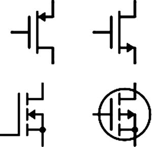
Figure 3-27 MOSFET schematic symbol
Junction Field Effect Transistor
The Junction Field Effect Transistor (JFET) is used for switching, amplification, and as a voltage controlled resistor. JFETs are not commonly used in normal circuit design, but do find use in specialty analog circuits. BJTs or MOSFETs can do most of what is required.
The JFET also finds use as a voltage controlled switch and as a chopper. Figure 3-28 shows the JFET schematic symbol.
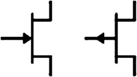
Figure 3-28 JFET schematic symbol
Operational Amplifier
The operational amplifier or op-amp is one of the fundamental building blocks of analog electronics. I would even go so far as to say that an op-amp is to analog electronics what a transistor is to digital ones. After you learn about microcontroller technology, I recommend you take an in-depth look at op-amps. With knowledge of op-amps and microcontrollers, you can design very powerful embedded systems. Figure 3-29 shows the op-amp schematic symbol.
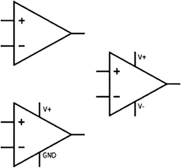
Figure 3-29 Op-amp schematic symbol
As the name implies, the op-amp is used for DC signal amplification. It is also used to filter and condition signals as well as for integration, differentiation, subtraction, and addition.
When looking at op-amp schematic symbols , in addition to the power supply pins (which are usually omitted), you will see two terminals, one with the minus sign and the other with the positive sign. The input with the positive sign is known as the non-inverting input and the one with the minus sign is called the inverting input. There is a third pin at the vertex of the triangular shaped op-amp symbol, known as the output port, and this pin can allow voltage or current to flow into the device, called sinking, or to supply current from the device, called sourcing.
Some common applications of op-amps in embedded systems design is as a buffer for the output of voltage divider voltage references, instrumentation amplifiers for differential pairs, active low-pass and high-pass filters, photodiode amplification, and more. In fact, an entire book can be written on op-amps and their applications!
There are hundreds of op-amps to choose from and I recommend you prototype with the TL081CP, KIA324, MCP6001, and MCP6002. These op-amps are great for rapid prototyping. Once you have a working system, you can determine the best amplifier for your needs.
Digital Electronics
Logic gates are the building blocks of digital circuits . When you combine several transistors, you get logic gates. I leave it up to you to read about the intricacies of digital electronics with regard to specific aspects of sequential and combinational circuits. Some basic gates are described in the following sections.
The AND Gate
The AND gate is one of the foundational building blocks of digital logic. The AND gate works by treating two logical inputs and outputs as a logical high only if both inputs are high. If only one of the inputs is high, then the output will be a logical low. Figure 3-30 shows the AND gate schematic symbol.
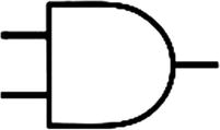
Figure 3-30 AND gate schematic symbol
The OR Gate
The OR gate works by outputting a logical high if either of its inputs are a logical high. If both inputs are a logical high, then the output is also a logical high. The only time the OR gate outputs a logical low is if both inputs are a logical low. Figure 3-31 shows the OR gate schematic symbol.
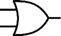
Figure 3-31 OR gate schematic symbol
The NOT Gate
The NOT gate, also known as an inversion gate, produces the exact opposite of its input. If the input is a logical high, then the output will be a logical low, and if the input is a logical low, then the output will be a logical high. Figure 3-32 shows the NOT gate schematic symbol.
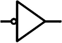
Figure 3-32 NOT gate schematic symbol
The NAND Gate
The NOT AND (NAND) gate is a logical gate that combines a NOT gate and an AND gate. The only distinguishing feature between the NAND gate and AND gate is the little circle on the end that symbolizes inversion. The NAND gate only gives a logical low if both its inputs are logical highs. Figure 3-33 shows the NAND gate schematic symbol.
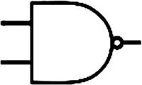
Figure 3-33 NAND gate schematic symbol
The NOR Gate
The NOT OR (NOR) gate is a logic gate that combines a NOT gate and an OR gate. The NOR gate, like the NAND gate, simply inverts the output of an OR gate and has the same distinguishing feature. Figure 3-34 shows the NOR gate schematic symbol.
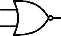
Figure 3-34 NOR gate schematic symbol
The Buffer Gate
The buffer gate is simply two NOT gates combined. The buffer gate might seem useless, but in actuality it has a lot of applications with logic-level conversion, discussed in the next section. Figure 3-35 shows the buffer gate schematic symbol.
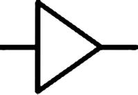
Figure 3-35 The buffer gate schematic symbol
The XOR Gate
The eXclusive OR (XOR) gate is a logic gate that gives a logic low when both inputs are true or when both inputs are false. It gives a logical high when both inputs are logically the opposite. Figure 3-36 shows the XOR gate schematic symbol.
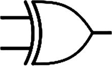
Figure 3-36 XOR gate schematic symbol
Logic-Level Conversion
An important concept to understand in the realm of digital electronics, especially when pertaining to interfacing microcontrollers, is the logic-level conversion. Before we discuss ways to convert between logic levels, we must first understand the concept of a logic level.
As you know in digital systems, data is represented in binary format, with a 0 representing off or low and a 1 representing on or high. While this knowledge may be sufficient for programming in general, when you use physical hardware, you must understand that low is 0 volts and high is the voltage that the system will recognize as a high signal when compared to the ground.
Early microcontroller systems used 5 volts as the standard, because this is the voltage with which the microcontroller and any external modules operate. Recently, however, the trend has been toward using 3.3v and even 1.8v as the voltage to power these systems. This presents a problem because a lot of existing modules, like LCDs for example, were made to use 5 volts, whereas newer microcontrollers typically use 3.3v. The problem also arises if you have a newer module that uses 3.3v logic and your systems runs on 5v logic.
In order to solve this problem, logic-level conversion is in order. Systems typically have some tolerance with their logic level. What this means is that if you have a 5v system, it will recognize a 3.3v signal as a logic high. However, you cannot drive a 3.3v logic-level system with 5 volts, as this will damage the module.
To avoid this, there are common ways to covert a 5v logic-level system to be interfaced with a 3.3 volt logic-level system, discussed next.
Run the Entire System on 3.3v
Although it’s not necessarily a logic-level conversion technique, running your system on 3.3v will eliminate any additional components being purchased, thus reducing your bill of materials (BOM) costs. In addition, running the entire system on 3.3v will lower overall power consumption. For these reasons, it is recommended that once it is possible, you lower the overall operating voltage of your system.
The PIC16F1717 and newer microcontrollers are capable of being run at 3.3v or 5v. In this book, I use 5v as much as possible, simply because a lot of modules and sensors cater to being used by a 5v system (although this is slowly changing). If you are an Arduino user, you may have built up your electronics arsenal with 5v components. Another advantage of 5v is that they are much less susceptible to being disturbed by noise than 3.3v ones, because you need more noise to disturb the operation of the 5v circuit. However, feel free to run your system at 3.3v in your end application.
Use a Voltage Divider
Using a voltage divider is another way to interface between logic-level signals (see Figure 3-37). As mentioned, if your 3.3v device is transmitting at 3.3v then you can directly connect this line to the 5v device input. However, on the transmitting end of the 5v device, it may be necessary to use a voltage divider to convert the higher logic level to a lower one.
A good resistor combination for this type of circuit is a 1k and 2k pair. The output would be close to 3.3v. The downside of this system is that it is best suited for very slow signals. If you are on a tight budget, then this is the method I recommend.
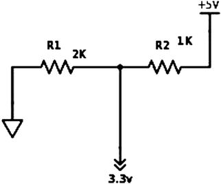
Figure 3-37 Voltage divider method
Use a Bi-Directional Logic Level Shifter
When you are interfacing between logic levels and a very high speed conversion needs to be done, it is simple to use a dedicated bi-directional logic-level shifter to convert between signal levels. For prototyping purposes, I recommend the ubiquitous logic-level converter modules, as they are designed for breadboarding and work well (see Figure 3-38). For moving to a PCB, I recommend the 74LVC245, because they are simple to use and work really well.
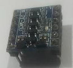
Figure 3-38 Common logic-level converter
Conclusion
This chapter looked at basic electronic components commonly found in embedded systems. We covered various components as well as basic logic gates and methods of logic-level conversion. This chapter is essential to understanding how to connect devices and sensors to your microcontroller. It was a very basic introduction; however, if you understand the content here, you should be able to construct your own circuits. If you need further information, there are books available that give a more detailed description of the components. There is also an app called Logic Gates for Android devices that allows users to experiment with logic gates.