PIC® Microcontrollers Overview
Microchip manufactures 8-, 16-, and 32-bit microcontrollers. In this chapter, we discuss the 8-bit families. 8-bit PIC® microcontrollers belong to different groups as microchip classifies them. They groups are baseline, mid-range, enhanced mid-range, and high-performance. We look at each of them in this chapter.
Baseline PIC® Microcontrollers
These are at the bottom of the 8-bit Microchip food chain. Baseline PIC® microcontrollers consists of family members from PIC10, PIC12, and PIC16. These devices are typically used in applications that need a low pin count, extremely low power requirements, and contain small programs. Some members of this family include an onboard oscillator. There are members of this family that have as few as six pins!
The PIC16F57 is one member of the baseline family that has found widespread use. The BASIC stamp I uses the PIC16C56 and the BASIC stamp II uses the PIC16F57 as its microcontrollers.
Mid-Range PIC® Microcontrollers
The mid-range family of PIC® microcontrollers have members in the PIC10, PIC12, and PIC16 families. These devices are used when you need more features, such as onboard communication peripherals and possibly core independent peripherals.
Devices such as the PIC16F877, 16F84A, and 16F887 were and still are very popular with microcontroller enthusiasts and there is a lot of code available for using these devices. However, unless you are supporting a legacy design, it is advisable to use the enhanced mid-range microcontrollers, which have a lot of useful features.
Enhanced Mid-Range PIC® Microcontrollers
The enhanced mid-range core includes members of the PIC12 and PIC16 families. This core was developed by Microchip to be compatible with the mid-range devices while offering several improvements, including more program memory, more on-chip peripherals, and of course the C optimized architecture.
In this book, we focus on the enhanced mid-range family of microcontrollers. The chip we are using—the PIC16F1717—has a lot of useful goodies onboard, including analog peripherals.
High-Performance PIC® Microcontrollers
These are the highest performing members of the PIC® 8-bit family and are members of the 18F family. They feature large Flash program memory, extended instruction set, and of course integrated protocol communications such as USB, CAN, and Ethernet. They are intended for high performance 8-bit devices and have hardware multipliers.
If you need to use USB, I recommend that you use the PIC18F4553 for your USB based projects. Though there are newer versions of the PIC18 family, this chip has a lot of existing code related to its use for USB applications, as it is identical to the PIC18F4550. The exception is that the PIC18F4553 contains a larger resolution analog-to-digital converter. However, I would generally say that if you require USB, a member of the PIC24 or PIC32 family provides a lot more powerful features.
PIC® 16F1717 Block Diagram
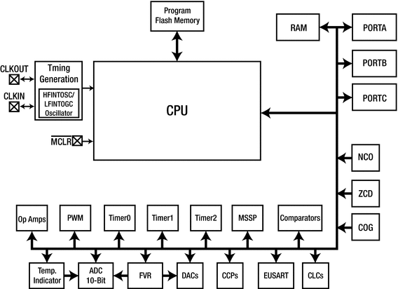
Now that you have learned about the different types of PIC® microcontroller families and groups, let’s look at the architecture of the PIC16F1717 (see Figure 4-1).

Figure 4-1 PIC16F1717 block diagram (reprinted with permission)
Looking at the block diagram shown in Figure 4-1, we see that the PIC16F1717 is very complex. It consists of a lot of peripherals, which we will discuss in the next few sections.
Program Flash Memory
The program Flash memory is memory that stores our program and is made from Flash memory technology. Older chips required UV light to erase their memory. However, with the advent of Flash-based technology, microcontrollers are extremely low cost and can be reprogrammed in seconds. Flash is also a non-volatile form of memory and features a long data retention. The PIC16F1717 Flash memory has a data retention of about 40 years!
The 8-bit PIC® microcontrollers’ Flash memory size usually consists of several kilobytes and, in the PIC16F1717, it is 14KB of program memory. This can store quite a lot of instructions, as you will see in this book. Microcontroller systems generally never use more than a couple of megabytes of program memory.
Random Access Memory
Random Access Memory (RAM) , as you know, stores program instructions to increase the speed of program execution. There are two main types of RAM—Static RAM (SRAM) and Dynamic RAM (DRAM) . There are other types of RAM, such as FRAM and EERAM; however, they will not be discussed here.
In your general-purpose computer, you find DRAM in the gigabyte range being used for memory. However, in microcontrollers, you find SRAM being used for main memory. General-purpose CPUs do contain SRAM; however, it is usually found on the processor and used for cache memory. The major differences are that SRAM retains its data if power is applied, whereas DRAM needs constant refreshing. SRAM is also faster than DRAM.
The PIC16F1717 contains 1024 bytes of SRAM. Now, before you complain about the tiny amount of RAM on this controller, let me tell you this is quite a lot. Microcontroller programs typically never require more than a few kilobytes of RAM.
Timing Generation
If you look at the block diagram in Figure 4-1, you see a block entitled “Timing Generation”. This block contains the HFINTOSC and LFINTOSC , which are the high-frequency internal oscillator and low-frequency internal oscillator, respectively. Also, not mentioned here, is the MFINTOSC (medium frequency internal oscillator). The LFINTOSC operates at 31kHz and is not calibrated. The MFINTOSC operates at 500kHz and is factory calibrated. The HFINTOSC derives its speed from the MFINTOSC and runs at a speed of up to 16MHz.
The maximum speed of the PIC16F1717 is 32MHz, which can be obtained by using the Phase Locked Loop (PLL) . PLLs are used to generate some multiple of the input frequency. The one onboard the PIC16F1717 is a 4x PLL, which means it will give an output frequency four times the input frequency.
PLLs have a period of time before they match the frequency and phase that is expected from them and when this is done the PLL is said to be locked. The PLL on the PIC16F1717 has a lock time of 2ms.
It is important to note that the HFINTOSC and MFINTOSC, although calibrated, fall within a margin of 2% of the stipulated frequency. Thus, if you need extremely accurate timing, an external oscillator would be required. However, in this book the internal oscillator would suffice.
!MCLR
The !MCLR pin is used to reset the PIC® microcontroller. When designing circuits, do not leave this pin floating. This pin must be connected to VDD if not in use. The circuit used for the !MCLR is shown below.
Ports
If you look at the microcontroller block diagram, you’ll notice several ports marked as PORTA to PORTE. On a microcontroller, there are several pins sticking out of it. Pins are used to interface the microcontroller to the outside world. However, inside the microcontroller these pins are controlled by registers within the microcontroller which are represented by ports.
Onboard Peripherals
The PIC® microcontroller consists of several digital peripherals. These peripherals are either digital or analog in nature. Microchip recently introduced a lot of core independent peripherals. Core independent peripherals require no intervention from the CPU to maintain operation. Let’s look at these peripherals.
Analog to Digital Converter
The Analog to Digital Converter (ADC) is used to convert analog signals to digital ones. The ADC converter onboard the PIC16F1717 has a resolution of 10 bits. What this means is that it can take a signal and break it into 1023 “steps,” with the value of a step being the input voltage divided by the number of steps.
For example, if we use a 4.096v voltage reference, then we have a resolution of 4mV per bit. For accurate ADC reading, it is advised to have a clean power supply and a stable voltage reference.
Digital to Analog Converter
The Digital to Analog Converter (DAC) does the exact opposite of the ADC. The DAC converts an analog signal to a digital one. The DAC is typically used to generate sound and waveforms. The PIC16F1717 has two DACs. DAC1 has a resolution of 8 bits and DAC2 has a resolution of 5 bits.
Capture/Compare/Pulse Width Modulation Module
The capture/compare/PWM (CCP module) is an important module on the PIC® microcontroller.
Capture mode is used to measure a particular number of falling or rising edges of a timer and essentially allows the timing of an event. Compare mode allows the comparing of the value of the timer to a preset comparison value. Pulse Width Modulation (PWM) mode generates a square wave of varying frequency and duty cycle, which can be determined by the user.
Pulse Width Modulation Module
In practice, I have found that one tends to use PWM more often because of its use in applications such as lighting and motor control. Even Microchip has realized the importance of PWM and provides a dedicated PWM module in addition to the regular CCP modules. The PWM module on the PIC16F1717 has a resolution of 10 bits.
Timers
Though you may see the word “Timerx ” in the block diagram of the microcontroller, the timers on board the PIC16F1717 can also function as counters and perform timer/counter functions. Timers are used for time measurement, pulse generation, and counting pulses, and are also very accurate time delays. Hence, although you may see these modules simply referred to as “timers,” bear in mind that they really perform Timer/Counter functions.
The PIC16F1717 has four 8-bit timers and one 16-bit timer. Timers 0, 2, 4, and 6 are 8-bit and timer 1 is 16-bit.
Comparators
The comparator on the PIC16F1717 compares two voltages and gives a digital output to indicate which is larger. The comparator has a minimum hysteresis of 20mV and a maximum of 75mV. It also has a response time of under 100ns.
Fixed Voltage Reference
The Fixed Voltage Reference (FVR) is used to provide a stable reference voltage to the comparator, DAC, or ADC. By doing this, the cost of paying for an external voltage reference is eliminated.
Temperature Indicator
There is a temperature indicator onboard the PIC16F1717 that has a range from -40 to 85 degrees Celsius. This temperature indicator is useful when you do not have space on the board for a temperature sensor or you want to reduce system cost.
EUSART
The Enhanced Universal Synchronous Asynchronous Receiver Transmitter (EUSART) module is used for serial communications and a lot of external modules require this interface to communicate with the microcontroller.
CLC
The Configurable Logic Cell (CLC) is a module on the microcontroller that provides a bit of onboard sequential and combinational logic functions.
MSSP
The Master Synchronous Serial Port (MSSP) module provides two modes of operation to be configured for use—either for Serial Peripheral Interface Function (SPI) or Inter-Integrated Circuit (I2C) functions.
NCO
The Numerically Controlled Oscillator (NCO) is used to provide a very precise and fine resolution frequency at a duty cycle. The NCO on the PIC 16F1717 uses the overflow of a 20-bit accumulator to achieve this function.
ZCD
The Zero Cross Detection module detects the point when there is no voltage present on the AC waveform. The ZCD module can be used to detect the fundamental frequency of a waveform and for sending digital data over AC circuits, such as what is done in X10 systems. The zero cross detect on the PIC16F1717 has a response time of 1uS.
COG
The Complementary Output Generator (COG) module takes one PWM signal and converts it into two complementary signals.
Operational Amplifiers
Operational Amplifiers (OPA) or Op Amps are the building block of analog systems. The PIC16F1717 includes onboard Op Amps. They have a gain bandwidth product of 2MHz and a slew rate of of 3V per uS, assuming a VDD of 3.0V.
High Endurance Flash Block
The High Endurance Flash (HEF) cell is designed to be a replacement for EEPROM, which is present on some microcontrollers. While the regular flash on the PIC16F1717 can withstand only 10,000 erase and write cycles, the HEF can withstand 100,000 erase and write cycles. The HEF has a size of 128 bytes.
The Enhanced Mid-Range CPU Core
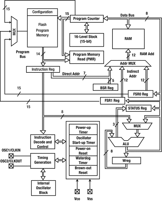
Now that you have a basic understanding of the onboard peripherals of the microcontroller, let’s take a look at the 8-bit CPU core (see Figure 4-2).

Figure 4-2 PIC16F1717 core diagram (reprinted with permission)
Let’s look at what some of these blocks in the core are responsible for. We will not discuss every detail of the architecture; however, the components that can be configured in software are discussed in the following sections.
Power-Up Timer
The power-up timer is responsible for providing a short delay to allow time for the power supply to reach to the required value. After the time has passed, the program can begin to execute. The reason for this is that it is a precaution to prevent adverse effects on program execution. The power-up timer takes between 40 and 140ms to do this.
Oscillator Start-Up Timer
The oscillator start-up timer (OST) provides a delay (in addition to the one offered by the power-up timer) to allow the clock to become stable before program execution begins. The OST counts for a period of 1024 cycles and is independent of the frequency of the microcontroller.
Power-On Reset
While the power-up timer and oscillator start-up timer are working, the power-on reset timer holds the device in reset until the power and clock stabilize.
Watchdog Timer
The watchdog timer (WDT) automatically resets the processor after a given period as defined by the user. This is extremely important in order to allow an application to escape from an endless loop. To keep the program running, the WDT must be cleared or else the program will not run as intended. It is therefore important to turn off the WDT when configuring the microcontroller.
Brown-Out Reset
The brown-out reset is used to detect a brown-out condition within the microcontroller. A brown-out condition is one in which there is a drop in voltage of the power supply. The brown-out reset circuitry holds the microcontroller in reset until the power supply returns to an acceptable level. The brown-out reset has a response time of between 1 to 35uS on the PIC16F1717 before it activates.
Conclusion
In this chapter, we briefly examined the PIC® microcontroller, which is the main topic of this book. Learn the information presented in this chapter and learn it well. The chapter covered some of the most important peripherals onboard the microcontroller as well as provided a general overview of some of the features of the core.
