Introducing Actuators
So far, we have covered input and output on the PIC® microcontrollers. In this chapter, we apply the knowledge we learned thus far to control three common actuators in embedded systems—the DC motor, the stepper motor, and the servo motor. We incrementally examine these three actuators based on their ability to be controlled. We start with the DC motor, which has very coarse control of directionality (forward or backward) and is the easiest to control. Next, we look at the servo, which has a greater degree of ability to be controlled, in that it can be positioned in one of three angles. Finally, the stepper motor has the finest level of granularity with control being down to very specific degree size.
DC Motor
When introducing actuation into embedded systems, the three most common types of actuators are pneumatic, hydraulic, and electric . Of these three, electric-based actuation is the easiest and cheapest to design and prototype with. A wide spectrum of devices, from electronic locks to toy cars and robots, use electric motors. Before we look at using an electric motor, let’s discuss it a bit. There are two types of electric motors. There are those that are powered by AC current and those that are DC powered. For the applications, we will look at the DC variety, specifically the brushed DC motor.
DC motors work on the principle of current flowing through a magnetic field, thereby creating a force. Electric motors are used to convert electrical energy into mechanical energy. DC motors contain two input terminals and applying a voltage across these terminals causes the motor shaft to spin. When positive voltage is applied, the motor spins in one direction; when negative voltage is applied, it spins in the other direction. In order to properly interface a DC motor to a microcontroller, we can use relays, MOSFETs, or transistors. The reason is simple:
If you connect a DC motor directly to the pin of your microcontroller, you will damage it!
Mind you, PIC® microcontrollers are very difficult to destroy when compared to other microcontrollers. I have had PIC® microcontrollers that were smoking and then worked for years after the problem was fixed, and still work! However, to ensure that you have a happy PIC® microcontroller, do not connect the motor directly to an I/O pin.
The reason that you cannot connect a motor directly to a PIC® microcontroller is that an inductive load such as a motor requires a large amount of current. The I/O pins of a PIC® microcontroller are incapable of supplying the current required by the motor. In order to interface small DC motors, such as a small hobby motors or vibration motors commonly used for haptic feedback in embedded systems, I recommend using a simple transistor when prototyping. The reason is that when working with MOSFETs , extra precautions need to be taken to prevent static damage. So you can prototype with a transistor and use a MOSFET for your final design.
Figure 7-1 shows how you connect a DC motor to the microcontroller.
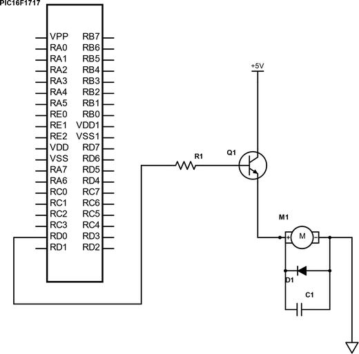
Figure 7-1 Driving motor with PIC16F1717
The value of the resistor, diode, and capacitors vary according to the size of the motor. For our purposes, the resistor can be 1k, the diode a standard 1N4001, and the capacitor a 0.1uF ceramic type. The transistor can be a 2n2222 or a 2n3904; however, almost any NPN transistor can be substituted. Be sure to consult the datasheet for your motor.
The code is rather simple, as shown in Listing 7-1.
Listing 7-1 PIC16F1717 Motor Control
/** File: Main.c* Author: Armstrong Subero* PIC: 16F1717 w/Int OSC @ 16MHz, 5v* Program: 07_Motor* Compiler: XC8 (v1.38, MPLAX X v3.40)* Program Version: 1.0*** Program Description: This Program Allows PIC16F1717 to Turn on a Motor** Hardware Description: As per schematics** Created November 4th, 2016, 1:00 PM*//********************************************************************************Includes and defines******************************************************************************/#include "16F1717_Internal.h"/******************************************************************************** Function: void initMain()** Returns: Nothing** Description: Contains initializations for main** Usage: initMain()******************************************************************************/void initMain(){// Run at 16 MHzinternal_16();// Set PIN D0 as outputTRISDbits.TRISD0 = 0;}/********************************************************************** Function: Main** Returns: Nothing** Description: Program entry point*********************************************************************/void main(void) {initMain();// Turn motor on for 5 secondswhile(1){LATD0 = !LATD0;__delay_ms(5000);}return;}
This should suffice for driving small motors for trivial applications. If we look at the code, the line that is responsible for actually turning the motor on is LATD0 = !LATD0. Just like in the LED program, this line drives the pin high for a period of five seconds, which turns the transistor on. When the while loop runs again, the pin outputs low, which turns the transistor off for a period of five seconds. You see even a simple application such as blinking an LED can be modified to perform other tasks in the real world. This is the power of microcontrollers. The five second on and off time is user determined and you may modify it as you see fit. If you want to have the motor turn in the other direction, you could do this by modifying the circuit and simply switching the terminals of the motor. To do so, connect the positive terminal to the ground and connect the negative terminal to the emitter of the transistor.
However, since we are using a microcontroller, I recommend that you use intelligent controls to modify the direction of the motor. In a later chapter, we will cover Pulse Width Modulation (PWM). In that same chapter, we will look at controlling a motor using the PWM on the PIC® microcontroller to control a motor driver.
Servo Motor
Now that you have a fair understanding of the DC motor, let’s look at the servo motor. There are many different types and sizes of servos. There are AC servos typically used for industrial applications and DC servos commonly used for smaller applications. In fact, there are servos that are used exclusively for robots and are known as robotic servos . They have ridiculous torque for their size.
When we speak of torque, we are talking about the maximum force the servo can output. The servo typically has three wires. One wire is connected to power, the other to ground, and the last is known as the signal wire and is connected to the pin of the microcontroller. We will not go into the intricacies of the internals of how servo motors are constructed. For our purposes, all we need to know is that a servo contains control circuitry inside. Therefore, all we need to do is tell this control circuitry what position to move the servo motor to.
To tell the servo motor what position to go to, we send a pulse on the signal wire. According to the width of the pulse (essentially how long the pulse is high), the motor will turn to the desired location. A servo motor can either move to one of three angles—0 degrees, 90 degrees, or 180 degrees.
There is one exception to this, which is the continuous rotation servo. It can rotate a full 360 degrees.
The technique of varying the width of a pulse is known as Pulse Width Modulation and we will discuss it in later chapters. For now, just know that we control the servo by changing the duration of the pulse on its signal wire. For simple applications, I recommend metal servos, as they have more torque for their size and are more accurate and durable.
You connect the servo motor as shown in Figure 7-2.
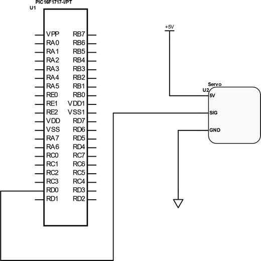
Figure 7-2 Driving servo with PIC16F1717
Create a file called Servo.h and use the code in Listing 7-2.
Listing 7-2 Servo Header File
/** File: Servo.h* Author: Armstrong Subero* PIC: 16F1717 w/Internal OSC @ 16MHz, 5v* Program: Header file to control a standard servo* Compiler: XC8 (v1.38, MPLAX X v3.40)* Program Version 1.0** Program Description: This program header will allow you control a standard* servo.*** Created on January 14th, 2017, 9:15 PM*//********************************************************************************Includes and defines******************************************************************************/#include "16F1717_Internal.h"void servoRotate0(); //0 Degreevoid servoRotate90(); //90 Degreevoid servoRotate180(); //180 Degree
Now you have to create a source file called Servo.c, which contains the code in Listing 7-3.
Listing 7-3 Servo Source File
/** File: Servo.c* Author: Armstrong Subero* PIC: 16F1717 w/Int OSC @ 16MHz, 5v* Program: Library file to configure PIC16F1717* Compiler: XC8 (v1.38, MPLAX X v3.40)* Program Version: 1.0** Program Description: This Library allows you to control a standard servo** Created on January 14th, 2017, 10:41 PM*/#include "16F1717_Internal.h"/******************************************************************************** Function: void servoRotate0()** Returns: Nothing** Description: Rotates servo to 0 degree position********************************************************************************/void servoRotate0(){unsigned int i;for(i=0;i<50;i++){RD0 = 1;__delay_us(700);RD0 = 0;__delay_us(19300);}}/******************************************************************************** Function: void servoRotate90()** Returns: Nothing** Description: Rotates servo to 90 degree position********************************************************************************/void servoRotate90() //90 Degree{unsigned int i;for(i=0;i<50;i++){RD0 = 1;__delay_us(1700);RD0 = 0;__delay_us(18300);}}/******************************************************************************** Function: void servoRotate90()** Returns: Nothing** Description: Rotates servo to 180 degree position********************************************************************************/void servoRotate180() //180 Degree{unsigned int i;for(i=0;i<50;i++){RD0 = 1;__delay_us(2600);RD0 = 0;__delay_us(17400);}
Listing 7-4 provides the main code.
Listing 7-4 Servo Main File
/** File: Main.c* Author: Armstrong Subero* PIC: 16F1717 w/Internal OSC @ 16MHz, 5v* Program: I02_Servo_Motor* Compiler: XC8 (v1.38, MPLAX X v3.40)* Program Version: 1.0*** Program Description: This demonstrates using a servo on a pic microcontroller** Hardware Description: A MG90s microservo is connected to PIN RD0** Created January 14th, 2017, 10:30 PM*//********************************************************************************Includes and defines******************************************************************************/#include "16F1717_Internal.h"#include "Servo.h"******************************************************************************** Function: void initMain()** Returns: Nothing** Description: Contains initializations for main** Usage: initMain()******************************************************************************/void initMain(){// Run at 16 MHzinternal_16();////////////////////// Configure Ports///////////////////// Make D0 OutputTRISDbits.TRISD0 = 0;// Turn off analogANSELD = 0;}/******************************************************************************** Function: Main** Returns: Nothing** Description: Program entry point******************************************************************************/void main(void) {initMain();// Rotate servo 0 - 90 - 180while(1){servoRotate0();servoRotate90();servoRotate180();return;}}
Once all goes well, the servo shaft will move along a 180-degree arc at 90-degree increments, starting at 0 degrees.
One caveat I should mention about actually using servo motors is that if you buy the cheap variety, or even the high-quality plastic ones, they may not actually start at 0 degrees and end at 180 degrees.
Stepper Motor
The stepper motor is the next topic of our actuator trio. Stepper motors are crucial to industrial applications and robotics. Stepper motors are used in many devices, including printers and CNC control, where very precise and controlled movement is needed.
The stepper motor has multiple coils which, when organized together, are called phases. Each phase is turned on sequentially, causing the stepper motor to rotate. The distance between each step is known as the step angle . Two major windings exist for the coils of the stepper motor. One is known as the unipolar and the other as the bipolar. The basic difference between the two is that, in the unipolar stepper motor, there is coil with a center tap per phase, whereas a bipolar motor has one winding per phase. In this book, we focus on the unipolar variety.
There are three main ways to drive a stepper motor. There is the wave drive, the full-step drive, and the half-step drive.
In the wave drive mode, only a single phase is activated at a time. This results in the wave drive mode using less power than other modes, but at the cost of loss of torque. The half-step drive mode alternates between two phases on and a single phase on. This increases angular resolution but lowers the torque. The full-step drive mode allows for two phases to be on at a time, thus allowing for maximum torque.
Thus, when designing with stepper motors, there is a tradeoff between torque, power consumption, and angular resolution.
The popular method for driving stepper motors though is to use the full-step drive mode; therefore, this is the method we will use in this book. In order to drive the stepper motor, we must use a driver to give the stepper motor the power it needs. For small stepper motors, you can use H-bridges or Darlington transistor arrays. We will use the Darlington array since from my experience they are simpler to use.
The IC we will use that contains these packages is the ULN2003A . The ULN2003A contains seven Darlington pairs and will be adequate for our purposes. The ULN2003A includes fly back diodes and can work up to 50V with a single output providing 500mA. These specifications make it a popular choice for driving small stepper motors. The motor we will use in this example is a four-phase unipolar stepper motor rated at 5v. The motor also has a holding torque of 110g-cm and a step angle of 7.5 degrees and requires a current of 500mA. Motors with similar specifications can be purchased from a variety of online suppliers; just ensure you buy one where the datasheet is easily accessible; otherwise, you may not know which wire does what. The circuit in Figure 7-3 indicates how you connect a stepper motor to the microcontroller.
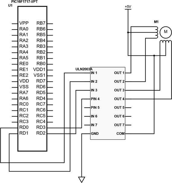
Figure 7-3 Stepper Motor Connection
The code in Listing 7-5 is rather straightforward and drives the stepper in full-step mode.
Listing 7-5 Stepper Main File
/** File: Main.c* Author: Armstrong Subero* PIC: 16F1717 w/Internal OSC @ 16MHz, 5v* Program: I03_Servo_Motor* Compiler: XC8 (v1.38, MPLAX X v3.40)* Program Version: 1.0*** Program Description: This demonstrates using a unipolar stepper motor with a* pic microcontroller.** Hardware Description: A Sinotech 25BY4801 4 phase unipolar stepper motor* is connected to PORT D of the microcontroller with a* ULN2003A darlington transistor array used as a driver* for the stepper motor.** Connections are as follows:** The ULN2003A is connected to the microcontroller as* shown below:** IN1 --> RD0* IN2 --> RD1* IN3 --> RD2* IN4 --> RD3** The Stepper motor is connected to the ULN2003A as* follows:** White = OUT1* Black = OUT2* Red = OUT3* Yellow = OUT4** Created January 15th, 2017, 12:05 AM*//********************************************************************************Includes and defines******************************************************************************/#include "16F1717_Internal.h"/******************************************************************************** Function: void initMain()** Returns: Nothing** Description: Contains initializations for main** Usage: initMain()******************************************************************************/void initMain(){// Run at 16 MHzinternal_16();////////////////////// Configure Ports///////////////////// Make D0 OutputTRISD = 0;// Turn off analogANSELD = 0;}/******************************************************************************** Function: Main** Returns: Nothing** Description: Program entry point******************************************************************************/void main(void) {initMain();while(1){LATD = 0b00001001; // Step 1__delay_ms(500);LATD = 0b00000101; // Step 2__delay_ms(500);LATD = 0b00000110; // Step 3__delay_ms(500);LATD = 0b00001010; // Step 4__delay_ms(500);}return;}
If you look in the main while loop in Listing 7-5, you’ll notice that the lower four bits of PORTD keep changing. In case you are wondering what is going on here, here is how it works. Remember we said that in full-drive step mode, the motor turns on two phases at a time? Well, if you revisit the schematic in Figure 7-3, you will notice that each phase of the stepper motor is connected to a pin of the microcontroller. Now I mentioned that the coils are center tapped in the unipolar variety stepper motor and, if you look at your schematic, this is shown in Figure 7-3. Therefore, two phases need to be turned on at a time, since in actuality current only flows in half the winding of the stepper motor at a time. Thus, if you look at the code, you will notice that two output pins are high at a time. This ensures that by energizing half windings of the two coils within the stepper motor alternately, you get the full 360 degree rotation of the motor.
If you are still having trouble understanding how this works, there are excellent resources on the web that go in-depth into the intricacies of the operation of stepper motors. In this book, however, you can safely ignore all the details of operation. As long as you verify with your datasheet that you have connected the stepper motor as shown in Figure 7-3, this code will work with unipolar stepper motors of any size.
Do not worry if your stepper motor runs hot. Stepper motors use a lot of current, and they use the same amount of current when they are stationary and running, so do not panic; this is completely normal.
Conclusion
This chapter looked at interfacing actuators to the PIC® microcontroller, including DC motors, stepper motors, and servo motors. These form the foundation for applications of PIC® microcontrollers in areas such as robotics and motor control.