Faculty of Computer Science, Universitas Indonesia, Depok, Indonesia
This chapter focuses on how to build Arduino Nano 33 IoT programs. We use Arduino Sketch to build Arduino programs. This software is available for Windows, macOS, and Linux. Then, we explore how to access Input/Output peripherals on the Arduino Nano 33 IoT board by the Arduino program.
In this chapter, you will learn:
how to write Arduino programs using Sketch
how to access digital I/O
how to access analog I/O
how to plot analog sensor analog
how to build a serial communication
how to access PWM
how to access SPI
how to scan an I2C address
how to read sensor device-based I2C
Introduction
We can say Arduino is a platform since Arduino as a company provides hardware and software. To build programs for Arduino Nano 33 IoT boards, we can use Arduino Sketch. This program uses C/C++ dialects as its language style.
In this chapter, we learn how to build programs for Arduino Nano 33 IoT. This is one of various Arduino models. The Arduino Nano 33 IoT board uses WiFi and Bluetooth modules to connect to a network. WiFi is a common network that people use to access Internet. Bluetooth is a part of wireless personal network (WPAN) that enables communication with other device in short distance.
We use Arduino software to build Arduino programs. This tool uses the Sketch program that uses C++ dialects. In the next section, we start to learn Sketch programming.
Basic Sketch Programming
In this section, we learn about Sketch programming language. Technically, Sketch uses C++ dialects, so if you have experience with C++ programming language, you can skip this section.
Main Program
The Arduino program has a main program to perform tasks continuously. When we create a program using Arduino software, we have skeleton codes with two functions: setup() and loop(). You can see the complete codes as follows.
void setup() {
// put your setup code here, to run once:
}
void loop() {
// put your main code here, to run repeatedly:
}
In these codes, we have two functions, setup() and loop(). The setup() function is called once when the Arduino board is turned on. If we put codes in the setup() function, it means our codes will run once. Otherwise, we have the loop() function that is called continuously.
This is a basic of the main program from Arduino. In this section, we learn Sketch programming with the following topics:
Declaring variables
Making a conditional statement
Making loops
Working with break and continue
Next, we start by declaring variables on the Sketch program.
Declare Variables
We can declare a variable using the following statement.
<data type> <variable name>;
<data type> is a keyword from the Sketch program that is adopted from the C++ program. <data type> represents how to define our data type on the variable. <variable name> is the variable name we will call and use in our program. A list of <data type> in the Sketch program can be seen in Table 2-1.
Table 2-1
Data Types on the Sketch Program
array
float
void
bool
int
String()
Boolean
long
unsigned char
Byte
short
unsigned int
char
size_t
unsigned long
double
string
word
Since the Sketch program adopts from C++, we put ; at the end of the code line. Otherwise, we obtain an error while compiling codes. For instance, we declare variables with int and char data types as follows:
int a;
int b = 10;
char c;
char d = 'A';
We can set an initial value while declaring a variable. For instance, we set int b = 10.
For a demo, we create a project for the Arduino Nano 33 IoT. Open the Arduino software and write these codes.
void setup() {
int a = 10;
int b = 5;
// initialize serial communication
Serial.begin(115200);
while (!Serial) {
;
}
int c = a + b;
int d = a * b;
// print
Serial.print("C= ");
Serial.println(c);
Serial.print("d= ");
Serial.println(d);
}
void loop() {
}
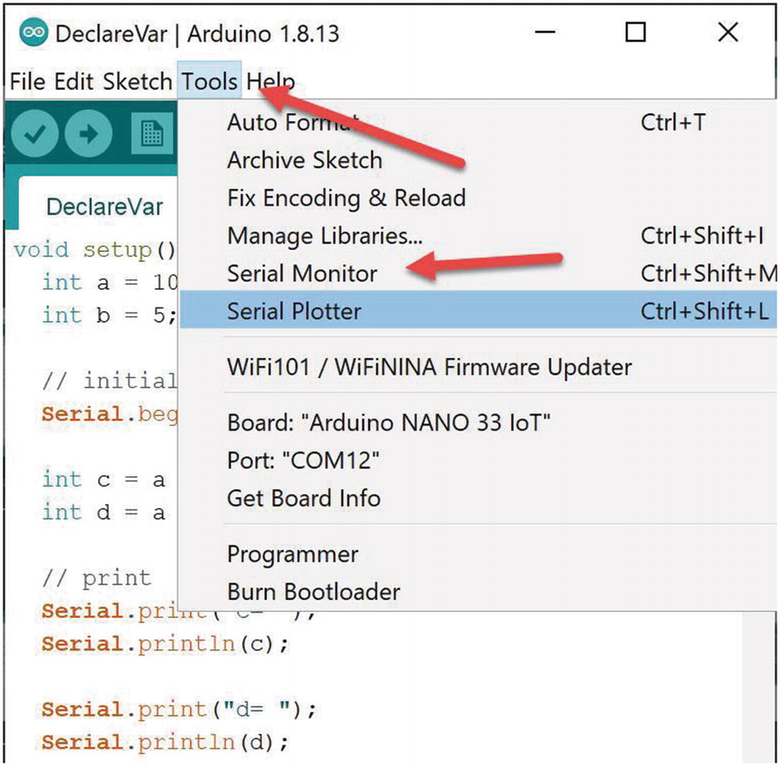
Figure 2-1 shows the aforementioned codes. To print messages, we use the Serial.print() and Serial.println() functions. We can print messages using Serial.print() without carriage return (“
”). Otherwise, we can print messages with carriage return using Serial.println().
Figure 2-1
Declaring variables
All printed messages with Serial library will be shown on the serial communication channel. Now we can save this program. Then, compile and upload to the Arduino Nano 33 IoT board.
To see the program output on the serial communication channel, we can use the Serial Monitor tool from Arduino. You can find it on the menu Tools ➤ Serial Monitor, as shown in Figure 2-2.
Figure 2-2
Opening the Serial Monitor tool
After clicking the Serial Monitor tool, we can see our program output. Select baudrate 115200 on the bottom of the Serial Monitor tool. You should see the program output in Serial Monitor. Figure 2-3 shows my program output in the Serial Monitor tool.
Figure 2-3
Program output on the Serial Monitor tool
If you don’t see the output message on the Serial Monitor tool, you can click the RESET button on the Arduino Nano 33 IoT board. You can find this button next to the micro USB connector. You can see the RESET button position in Figure 2-4.
Figure 2-4
Clicking the RESET button on the Arduino Nano 33 IoT
How does it work?
This program only runs on the setup() function. We declare two variables, a and b. Then, we assign their values.
void setup() {
int a = 10;
int b = 5;
Next, we activate the Serial object to perform serial communication. We set baud rate at 115200. We use while looping syntax to wait on creating Serial object.
// initialize serial communication
Serial.begin(115200);
while (!Serial) {
;
}
We perform simple mathematic operations such as addition and multiplication. The result of the operations is stored in the c and d variables.
int c = a + b;
int d = a * b;
We print the result to serial terminal using the Serial object.
// print
Serial.print("C= ");
Serial.println(c);
Serial.print("d= ");
Serial.println(d);
On the loop() function, we do nothing. All codes run on the setup() function. That’s why you probably don’t see the program output, because we see it late.
void loop() {
}
Operators
The Sketch program adopts C++ operators. We can declare arithmetic operators to perform mathematic operations. We can use the following arithmetic operators:
% (remainder)
* (multiplication)
+ (addition)
- (subtraction)
/ (division)
= (assignment operator)
For Boolean operators, we implement && for logical, || for logical or, and ! for logical not.
Conditional Statement
We can perform action-based conditions. For instance, we want to turn on a lamp if a light sensor obtains a low intensity value. In Sketch, we implement a conditional statement using if and switch syntax. A conditional statement with if can be declared as follows:
if(<conditional>) {
// do something
} else {
// do something
}
We can put a conditional value on <conditional> such as applying Boolean and arithmetic operators. For a demo, we can create a Sketch program on the Arduino Nano 33 IoT. You write this complete program.
long num_a;
long num_b;
void setup() {
// initialize serial communication
Serial.begin(115200);
while (!Serial) {
;
}
}
void loop() {
num_a = random(100);
num_b = random(100);
// print
Serial.print("num_a: ");
Serial.print(num_a);
Serial.print(", num_b: ");
Serial.println(num_b);
if(num_a > num_b) {
Serial.println("num_a > num_b");
}else {
Serial.println("num_a <= num_b");
}
delay(2000);
}
Save this program as conditional. Now you can compile and upload this program into the Arduino Nano 33 IoT board. Open the Serial Monitor tool so you can see this program output. Figure 2-5 shows my program output for a conditional program.
Figure 2-5
Program output for a conditional if program
How does this work?
This program generates random values for num_a and num_b variables on the loop() function.
void loop() {
num_a = random(100);
num_b = random(100);
Next, we print these random values on the serial terminal using the Serial object. We can call the Serial.print() and Serial.println() functions.
// print
Serial.print("num_a: ");
Serial.print(num_a);
Serial.print(", num_b: ");
Serial.println(num_b);
Last, we evaluate a value on num_a and num_b using a conditional-if statement. We check if the num_a value is greater than num_b or not. Then, we print the result on the serial terminal.
if(num_a > num_b) {
Serial.println("num_a > num_b");
}else {
Serial.println("num_a <= num_b");
}
The next demo is to implement a conditional with switch statement. In general, we can declare a switch statement as follows.
switch(value) {
case val1: <code>
break;
case val2: <code>
break;
case val3: <code>
break;
}
For the demo, we build a program to evaluate the num_a value with a switch statement. We set a random value with a maximum value of 5. Open Arduino software and write this complete program.
long num_a;
void setup() {
// initialize serial communication
Serial.begin(115200);
while (!Serial) {
;
}
}
void loop() {
num_a = random(5);
// print
Serial.print("num_a: ");
Serial.println(num_a);
switch(num_a) {
case 0:
Serial.println("num_a value is 0");
break;
case 1:
Serial.println("num_a value is 1");
break;
case 2:
Serial.println("num_a value is 2");
break;
case 3:
Serial.println("num_a value is 3");
break;
case 4:
Serial.println("num_a value is 4");
break;
}
delay(2000);
}
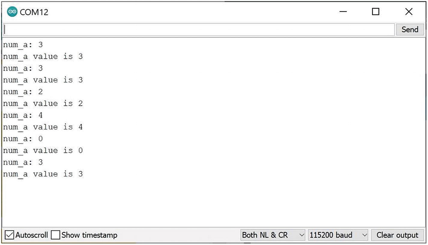
Save this program as ConditionalSwitch. You can compile and upload this program into Arduino Nano 33 IoT. To see the program output, and you can open the Serial Monitor tool. You can see my program output in Figure 2-6.
Figure 2-6
Program output on the switch program
How does this work?
This program starts to generate random values on the loop() function. The result is be stored in the num_a variable. Then, we print this value to a serial terminal.
void loop() {
num_a = random(5);
// print
Serial.print("num_a: ");
Serial.println(num_a);
Next, we evaluate the num_a variable using a switch statement. We check num_a for value: 0, 1, 2, 3, and 4. We print the message on each switch-case statement.
switch(num_a) {
case 0:
Serial.println("num_a value is 0");
break;
case 1:
Serial.println("num_a value is 1");
break;
case 2:
Serial.println("num_a value is 2");
break;
case 3:
Serial.println("num_a value is 3");
break;
case 4:
Serial.println("num_a value is 4");
break;
}
You have learned conditional statements with if and switch. In my opinion, you can use switch statements if the options are below 5; otherwise, you can use an if-statement with operators.
Looping
The looping task is useful when you perform the same task continuously. In the Sketch program, we can implement looping tasks using for, while, and do..while statements. We can declare a for-statement as follows.
for(start;conditional;increment/decrement) {
<codes>
}
For a while statement, we can implement as follows.
while(selection) {
<codes>
}
We also can use do..while for looping. You can run the first code step, then we select a while statement.
do {
<codes>
} while(selection);
Now we can build a Sketch program to implement looping using for, while, and do..while statement. Write this complete program using the Arduino software.
void setup() {
// initialize serial communication
Serial.begin(115200);
while (!Serial) {
;
}
}
void loop() {
long val = random(15);
int i;
// print
Serial.print("val: ");
Serial.println(val);
// looping
Serial.println("Looping: for");
for(i=0;i<val;i++){
Serial.print(i);
Serial.print(" ");
}
Serial.println();
Serial.println("Looping: while");
int start = 0;
while(start < val) {
Serial.print(start);
Serial.print(" ");
start++;
}
Serial.println();
Serial.println("Looping: do..while");
start = 0;
do {
Serial.print(start);
Serial.print(" ");
start++;
}while(start < val);
Serial.println();
delay(3000);
}
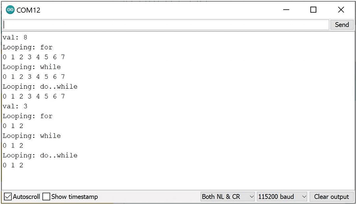
You can save this program as Looping. You can compile and upload this program into the Arduino Nano 33 IoT board. After uploading a program into the Arduino Nano 33 IoT board, you can open the Serial Monitor tool to see program output. You can see my program output in Figure 2-7.
Figure 2-7
Program output for looping
How does it work?
We set a random value for our looping program.
void loop() {
long val = random(15);
int i;
We print this random value to serial terminal.
// print
Serial.print("val: ");
Serial.println(val);
For looping with a for statement, we perform a loop starting with i=0 until we reach val value.
Serial.println("Looping: for");
for(i=0;i<val;i++){
Serial.print(i);
Serial.print(" ");
}
Serial.println();
For a while statement, we perform a similar task to the for statement. We set start = 0 for initialization.
int start = 0;
while(start < val) {
Serial.print(start);
Serial.print(" ");
start++;
}
Serial.println();
Last, we implement a do..while statement. We set start=0 again. Then, we perform a looping task.
start = 0;
do {
Serial.print(start);
Serial.print(" ");
start++;
}while(start < val);
Serial.println();
Break and Continue
When we perform looping, we probably want to exit from looping or skip a certain step from looping. In the Sketch program, we can use break and continue statements.
For demo, we create the Sketch program to perform looping from 0 to a random value. When the looping iteration reaches 5, we skip this step using a continue statement. Then, we exit from looping when we reach an iteration value more than 10 using a break statement.
Now we can open Arduino software. We can write this complete program for break and continue implementation.
void setup() {
// initialize serial communication
Serial.begin(115200);
while (!Serial) {
;
}
}
void loop() {
long val = random(6, 15);
int i;
// print
Serial.print("val: ");
Serial.println(val);
// looping
Serial.println("Looping: for");
for(i=0;i<val;i++){
if(i==5)
continue;
if(i>10)
break;
Serial.print(i);
Serial.print(" ");
}
Serial.println();
delay(3000);
}
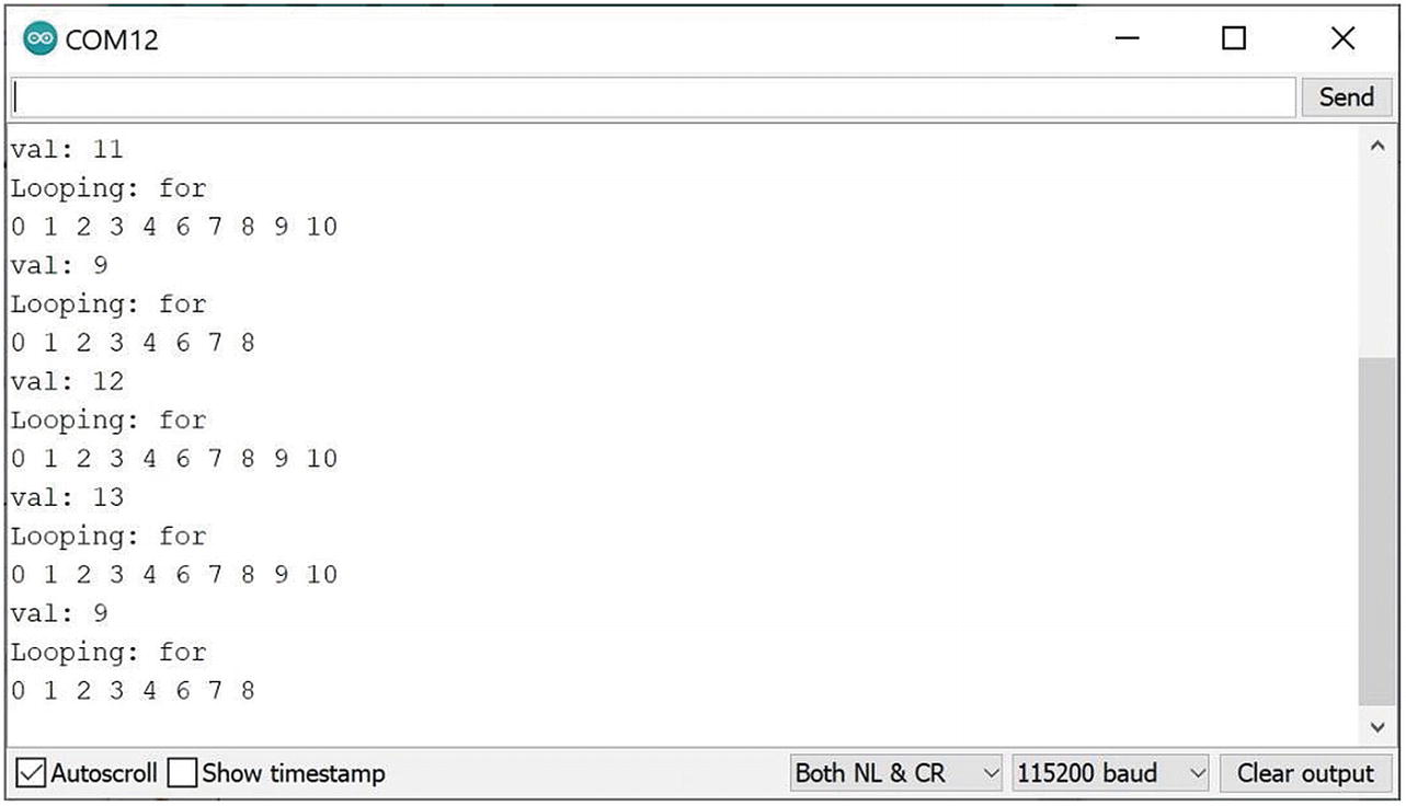
Save this program as BreakContinue. Compile and upload this program into Arduino Nano 33 IoT. After uploading the program, we can see program output using the Serial Monitor tool, You can see my program output in Figure 2-8.
Figure 2-8
Applying break and continue on the Sketch program
How does it work?
We set a random value on the loop() function. We print this random value to the serial terminal using Serial object.
void loop() {
long val = random(6, 15);
int i;
// print
Serial.print("val: ");
Serial.println(val);
We perform looping from 0 to a random value, val. When we have iteration = 5, we skip this iteration using the continue statement. Then, when we have iteration >10, we exit from looping by calling the break statement.
// looping
Serial.println("Looping: for");
for(i=0;i<val;i++){
if(i==5)
continue;
if(i>10)
break;
Serial.print(i);
Serial.print(" ");
}
Serial.println();
This is the end of the basic Sketch program. Next, we write an Arduino program with various cases.
Digital I/O
Arduino Nano 33 IoT has digital input/output about 14 pins. We can perform to attach sensors and actuators into digital I/O pins. You can see the Arduino Nano 33 IoT pin layout on the back of the board. Figure 2-9 shows the back of the Arduino Nano 33 IoT. Digital I/O pins are defined as Dx, where x is a digital number; for instance, D1 is digital I/O on pin 1.
Figure 2-9
Arduino Nano 33 IoT pinout
To implement demo for digital I/O on the Arduino Nano 33 IoT, we need an LED and a push button. We will use internal LED (built-in LED) on digital pin 13. We also need a push button that is connected to digital pin 7. You can see our project wiring in Figure 2-10.
Figure 2-10
A wiring for a push button project
Now we create the Arduino program. In this program, we turn on the LED when the user clicks a push button. The program algorithm is to read a push button state using the digitalRead() function. To turn on the LED, we can use digitalWrite() and set HIGH value.
Open Arduino software. We can implement our program. Write this complete program.
int led = 13;
int pushButton = 7;
int state = 0;
void setup() {
pinMode(led, OUTPUT);
pinMode(pushButton, INPUT);
}
void loop() {
state = digitalRead(pushButton);
digitalWrite(led,state);
delay(300);
}
Save this program as ButtonLed. You can compile and upload this program to Arduino Nano 33 IoT. After uploading, you can test by clicking a push button. You should see a lighting LED on Arduino Nano 33 IoT.
How does this work?
This program starts by initializing values for LED and push button pins.
int led = 13;
int pushButton = 7;
int state = 0;
void setup() {
pinMode(led, OUTPUT);
pinMode(pushButton, INPUT);
}
Then, on the loop() function, we read a push button state using the digitalRead() function. The state value will be passed to the digitalWrite() function to turn on/off LED.
void loop() {
state = digitalRead(pushButton);
digitalWrite(led,state);
delay(300);
}
Now that we have learned about digital I/O, we will learn analog I/O in the next section.
Analog I/O
Arduino Nano 33 IoT provides analog I/O to enable us to make interaction with sensor and actuator devices. We can see analog I/O pins with labeling Ax, where x is analog pin number. You can see these labels on the back of Arduino Nano 33 IoT.
You can see these pins in Figure 2-9. Arduino Nano 33 IoT has eight analog inputs (ADCs) and one analog input (DAC). For ADC model, Arduino Nano 33 IoT provides ADC resolution with 8-, 10-, and 12-bit. Furthermore, DAC model has a 10-bit resolution.
For our demo, we use the analog sensor TMP36. It’s a temperature sensor. You can also use TMP36 module like thermal module from Linksprite, https://www.linksprite.com/wiki/index.php?title=Thermal_Module. You can perform wiring as shown in Figure 2-11. You can build this following wiring:
TMP36 module VCC is connected to Arduino 3.3.V
TMP36 module GND is connected to Arduino GND
TMP36 module SIG is connected to Arduino analog A0
Figure 2-11
Wiring for analog sensor and Arduino Nano 33 IoT
Now we can write an Arduino Program to analog sensor from TMP36 module. We read sensor data and then show it on a serial terminal. You can start by opening Arduino software and write this complete program.
void setup() {
Serial.begin(115200);
while (!Serial) {
;
}
}
void loop() {
int reading = analogRead(A0);
float voltage = reading * 3.3;
voltage /= 1024.0;
Serial.print(voltage); Serial.println(" volts");
float tempC = (voltage - 0.5) * 100 ;
Serial.print(tempC);
Serial.println(" degrees C");
delay(3000);
}
Save this program as AnalogSensor. Now you can compile and upload this program into Arduino Nano 33 IoT. Open the Serial Monitor tool to see program output. Figure 2-12 shows my program output for the AnalogSensor program.
Figure 2-12
Program output for reading temperature
How does it work?
First, we read sensor data on analog pin A0.
void loop() {
int reading = analogRead(A0);
Then, we calculate a voltage and show it on the serial terminal. Since we use a voltage reference of 3.3V, we can calculate using this formula:
float voltage = reading * 3.3;
voltage /= 1024.0;
Serial.print(voltage); Serial.println(" volts");
Now we can compute a temperate using the following formula-based datasheet from TMP36 module.
float tempC = (voltage - 0.5) * 100 ;
Serial.print(tempC);
Serial.println(" degrees C");
The result is be printed on serial terminal.
Plotting Analog Sensor
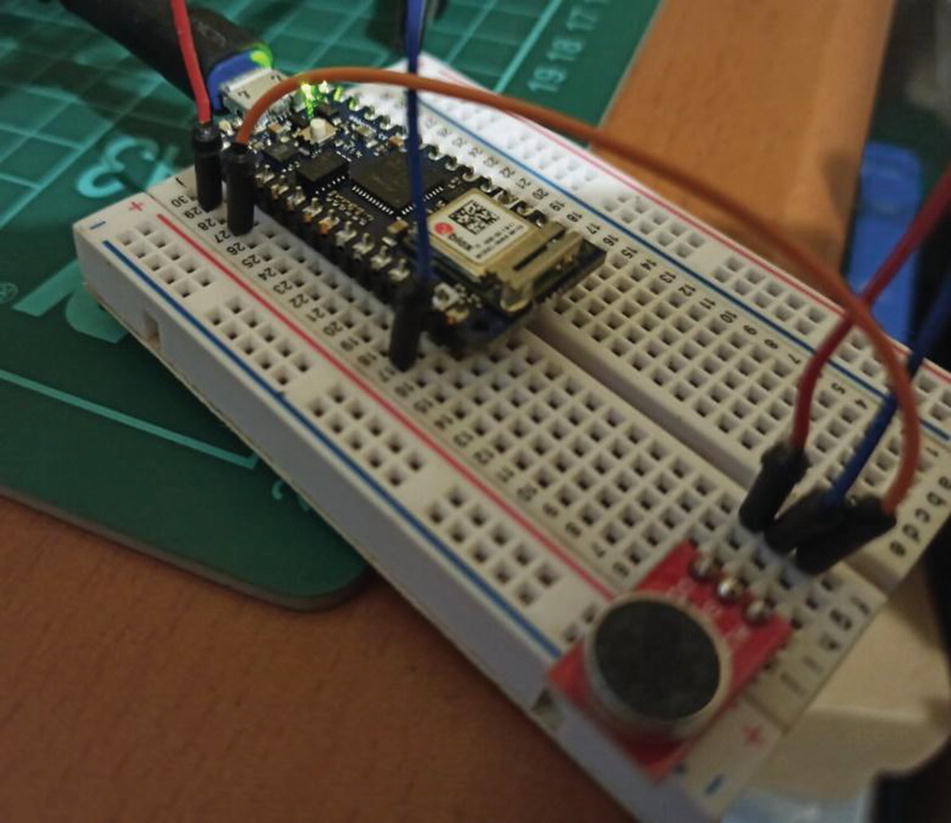
We also can plot analog input on the plotter tool. This tool is available on Arduino software. For our demo, we use a SparkFun Electret Microphone Breakout as an analog source. You can find this module on the link https://www.sparkfun.com/products/12758.
Now we can connect a SparkFun Electret Microphone Breakout to Arduino Nano 33 IoT. You can build this following the wiring:
SparkFun Electret Microphone Breakout module VCC is connected to Arduino 3.3.V.
SparkFun Electret Microphone Breakout module GND is connected to Arduino GND.
SparkFun Electret Microphone Breakout module SIG is connected to Arduino A0.
Arduino wiring with SparkFun Electret Microphone Breakout
Now we can write Arduino program to plot sensor data. Open Arduino software and write this complete program.
void setup() {
Serial.begin(115200);
while (!Serial) {
;
}
}
void loop() {
int val = analogRead(A0);
Serial.println(val);
delay(300);
}
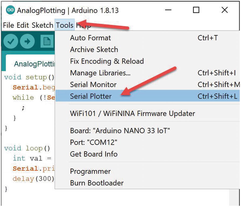
Save this program as AnalogPlotting. Now you can compile and upload this program into Arduino Nano 33 IoT. Open the Serial Plotter tool on Arduino software, and click the menu Tools ➤ Serial Plotter, as shown in Figure 2-14.
Figure 2-14
Opening the Serial Plotter tool
After you click the Serial Plotter, you will obtain a dialog as shown in Figure 2-15. Make noise on SparkFun Electret Microphone Breakout so we can obtain various signals on the plotter tool. Since we use delay(300), plotter updates its graphs every 300 ms.
Figure 2-15
Plotting sensor data
How does it work?
This program works very simply. First, we read an analog sensor by calling analogRead().
void loop() {
int val = analogRead(A0);
Then, we print to the serial terminal using println() from the Serial object.
Serial.println(val);
delay(300);
This makes the Serial Plotter tool display a graph.
Serial Communication
Serial communication is the process of sending data one bit at a time, sequentially, over a communication channel. In Arduino Nano 33 IoT, we can implement serial communication using the Serial object. We already used this Serial object in previous projects to show program output using the Serial Monitor tool.
For the demo, we build a blink program. Each LED state is written into a serial terminal. We use baudrate 115200. You can open Arduino software and write this complete program.
int led = 13;
void setup() {
Serial.begin(115200);
pinMode(led, OUTPUT);
}
void loop() {
Serial.println("LED: HIGH");
digitalWrite(led, HIGH);
delay(1000);
Serial.println("LED: LOW");
digitalWrite(led, LOW);
delay(1000);
}
Save this program as SerialDemo. Now you can compile and upload this program into Arduino Nano 33 IoT. Open the Serial Monitor tool to see the program output. Figure 2-16 shows my program output for the SerialDemo program.
Figure 2-16
Program output for the SerialDemo program
Pulse Width Modulation
Pulse width modulation (PWM) is a method to control analog output. Technically, it's not "true" analog output. A microcontroller unit (MCU) can manipulate duty cycles to generate pulses. Arduino Nano 33 IoT has a PWM pin on digital pins. You can see a sign "~" on digital pins as a PWM pin. You can see that Figure 2-9 shows a digital pin such as D2 ~. In general, Arduino Nano 33 IoT has 11 PWM pins on 2, 3, 5, 6, 9, 10, 11, 12, 16/A2, 17/A3, and 19/A5.
For our demo, we use RGB LED. This LED has four pins. Three pins are red, green, and blue pins. The rest could be ground (GND) or voltage common collector (VCC), depending on RGB cathode or anode model.
We can implement our demo wiring as shown in Figure 2-17. You can perform the wiring as follows:
RGB red pin is connected to Arduino digital pin 12.
RGB green pin is connected to Arduino digital pin 11.
RGB blue pin is connected to Arduino digital pin 10.
RGB GND pin is connected to Arduino digital pin GND.
Figure 2-17
Wiring for Arduino and RGB LED
Now we create the Arduino program to generate some colors with RGB LED. We will make colors such as red, green, blue, yellow, purple, and aqua. You can open Arduino software and write this complete program.
int redPin = 12;
int greenPin = 11;
int bluePin = 10;
void setup()
{
pinMode(redPin, OUTPUT);
pinMode(greenPin, OUTPUT);
pinMode(bluePin, OUTPUT);
Serial.begin(115200);
}
void loop()
{
setColor(255, 0, 0); // red
Serial.println("red");
delay(1000);
setColor(0, 255, 0); // green
Serial.println("green");
delay(1000);
setColor(0, 0, 255); // blue
Serial.println("blue");
delay(1000);
setColor(255, 255, 0); // yellow
Serial.println("yellow");
delay(1000);
setColor(80, 0, 80); // purple
Serial.println("purple");
delay(1000);
setColor(0, 255, 255); // aqua
Serial.println("aqua");
delay(1000);
}
void setColor(int red, int green, int blue)
{
analogWrite(redPin, red);
analogWrite(greenPin, green);
analogWrite(bluePin, blue);
}
Save this program as test_rgb_arduino. Now you can compile and upload this program into Arduino Nano 33 IoT. You should see some colors on RGB LED. You also can open the Serial Monitor tool to see the program output. Figure 2-18 shows my program output for the test_rgb_arduino program.
Figure 2-18
Program output for the RGB application
How does it work?
We initialize digital pins for PWM pins. We call pinMode() with OUTPUT mode. We also configure serial with baudrate 115200.
int redPin = 12;
int greenPin = 11;
int bluePin = 10;
void setup()
{
pinMode(redPin, OUTPUT);
pinMode(greenPin, OUTPUT);
pinMode(bluePin, OUTPUT);
Serial.begin(115200);
}
We also define the setColor() function to generate a color from combining red, green, and blue color values. We call analogWrite() to write data for PWM data.
void setColor(int red, int green, int blue)
{
analogWrite(redPin, red);
analogWrite(greenPin, green);
analogWrite(bluePin, blue);
}
Next, we generate some colors on the loop() function. For instance, we want to set red = 255, green = 0, and blue = 0. These sample for generating colors for red, green, and blue.
void loop()
{
setColor(255, 0, 0); // red
Serial.println("red");
delay(1000);
setColor(0, 255, 0); // green
Serial.println("green");
delay(1000);
setColor(0, 0, 255); // blue
Serial.println("blue");
delay(1000);
We also generate colors for yellow, purple, and aqua by inserting values for red, green, and blue.
setColor(255, 255, 0); // yellow
Serial.println("yellow");
delay(1000);
setColor(80, 0, 80); // purple
Serial.println("purple");
delay(1000);
setColor(0, 255, 255); // aqua
Serial.println("aqua");
delay(1000);
You can practice generating new colors by combining values for red, green, and blue. We can only set values from 0 to 255.
Serial Peripheral Interface
Serial communication works with asynchronous mode so there is no control on serial communication. This means we cannot guarantee the data that is sent will be received by receiver. The serial peripheral interface (SPI) is a synchronous serial communication interface specification, but SPI has four wires to control data such as master out/slave in (MOSI), master in/slave out (MISO), serial clock signal (SCLK), and slave select (SS).
Arduino Nano 33 IoT has one SPI interface with the following SPI pins:
MOSI on Digital pin 11
MISO on Digital pin 12
SCLK on Digital pin 13
You can attach any sensor or actuator-based SPI interface on Arduino Nano 33 IoT. For our demo, we only connect the MISO pin to the MOSI pin using a jumper cable. You can connect digital pin 12 to digital pin 11. Figure 2-19 shows my wiring for the SPI demo.
Figure 2-19
Connecting MISO and MISO pins from Arduino SPI
To access the SPI interface on Arudino Nano 33 IoT, we can use the SPI library. You can obtain a detailed information about this library at this link, https://www.arduino.cc/en/Reference/SPI.
Now we can build the Arduino program. Our program will send data to SPI and receive data from SPI. Open Arduino software and then write this complete program.
#include <SPI.h>
byte sendData,recvData;
void setup() {
SPI.begin();
Serial.begin(9600);
randomSeed(80);
}
void loop() {
sendData = random(50, 100);
recvData = SPI.transfer(sendData);
Serial.print("Send=");
Serial.println(sendData,DEC);
Serial.print("Recv=");
Serial.println(recvData,DEC);
delay(800);
}
Save this program as SPIDemo. Now you can compile and upload this program into Arduino Nano 33 IoT. You can open the Serial Monitor tool to see program output. Figure 2-20 shows my program output for the SPIDemo program.
Figure 2-20
Program output for the SPI program
How does it work?
We initialize SPI and Serial interface on the setup() function.
#include <SPI.h>
byte sendData,recvData;
void setup() {
SPI.begin();
Serial.begin(9600);
randomSeed(80);
}
To send and receive data over SPI, we can use the SPI.transfer() function. We send data with a random value on the loop() function.
void loop() {
sendData = random(50, 100);
recvData = SPI.transfer(sendData);
Then, we print sent data and received data on serial terminal.
Serial.print("Send=");
Serial.println(sendData,DEC);
Serial.print("Recv=");
Serial.println(recvData,DEC);
You have completed the SPI demo. You can practice more with SPI by applying sensors or actuator devices.
Interintegrated Circuit (I2C)
The interintegrated circuit (I2C) protocol is a protocol intended to allow multiple "slave" module/device (chip) to communicate with one or more "master" chips. This protocol works with asynchronous mode. To communicate with other devices/modules, I2C protocol defines the I2C address for all "slave" devices.
The I2C interface has two pins: serial data (SDA) and serial clock (SCL). For data transfer, the I2C interface uses an SDA pin. An SCL pin is used for clocking. The Arduino Nano 33 IoT board has I2C pins on A4 as SDA and A5 as SCL.
For our demo, we use a sensor module-based I2C interface. The I2C interface uses a device address so the Arduino Nano 33 IoT board can access data by opening a connection to the I2C address. Each analog sensor from sensor module-based I2C will be attached to the I2C address.
You can find the chip at an online store like Aliexpress. You can probably obtain this module at your local store.
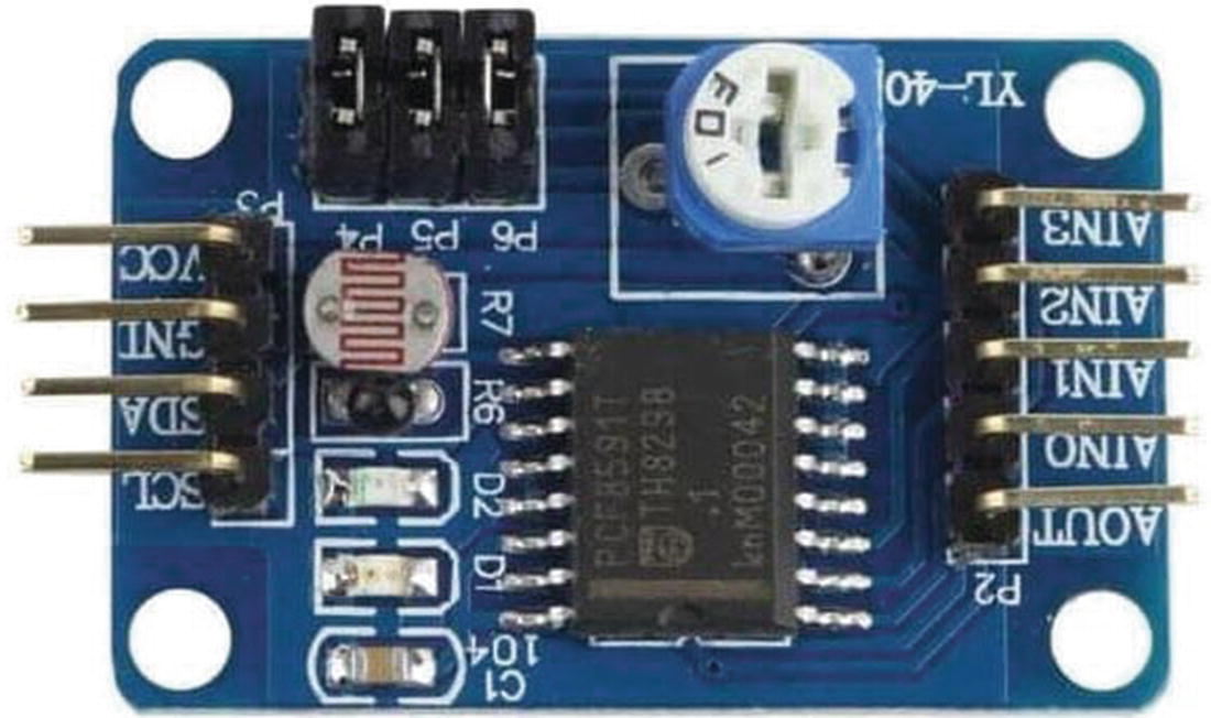
Based on datasheet documentation of the PCF8591 AD/DA converter module, this module uses I2C addresses on 0x48. The PCF8591 AD/DA converter module also consists of three sensors as follows:
Thermistor: using channel 0
Photoresistor: using channel 1
Potentiometer: using channel 3
Now attach the PCF8591 AD/DA converter module to the Arduino Nano 33 IoT board with the following wiring:
The PCF8591 AD/DA module SDA is connected to Arduino A4 pin.
The PCF8591 AD/DA module SCL is connected to Arduino A5 pin.
The PCF8591 AD/DA module VCC is connected to Arduino 3.3V.
The PCF8591 AD/DA module GND is connected to Arduino GND pin.
Figure 2-22 shows my wiring for the PCF8591 AD/DA converter module and Arduino Nano 33 IoT. You should see a lighting LED when we plug in 3.3V to the module.
We have finished our wiring for this demo. Next, we will implement two project demos as listed here:
I2C scanning application
I2C sensor application
Next, we build a scanning I2C address application on the Arduino Nano 33 IoT board.
Scanning I2C Address
Every device/module-based I2C set owns an I2C address on MCU. In this section, we want to scan all devices that are attached on Arduino Nano 33 IoT. We also have two internal sensor device-based I2Cs inside Arduino Nano 33 IoT.
To access I2C on the Arduino board, we can use the Wire library. We can include our program by inserting the wire.h library. For further information about the Wire library, we can read on the official website from Arduino (https://www.arduino.cc/en/Reference/Wire).
For our demo, we use our wiring demo from the PCF8591 AD/DA converter module (see Figure 2-22). Open Arduino software and write this complete program.
#include <Wire.h>
void setup() {
Serial.begin(115200);
Wire.begin();
Serial.println("
I2C Scanner");
}
void loop() {
byte error, address;
int nDevices;
Serial.println("Scanning...");
nDevices = 0;
for(address = 1; address < 127; address++) {
Wire.beginTransmission(address);
error = Wire.endTransmission();
if (error == 0) {
Serial.print("I2C device found at address 0x");
if (address < 16)
Serial.print("0");
Serial.println(address, HEX);
nDevices++;
}
else if (error == 4) {
Serial.print("Unknown error at address 0x");
if (address < 16)
Serial.print("0");
Serial.println(address, HEX);
}
}
if (nDevices == 0)
Serial.println("No I2C devices found");
else
Serial.println("done");
delay(5000);
}
Save this program as i2c_scanner. Now you can compile and upload this program into Arduino Nano 33 IoT. We can see program output using Serial Monitor.
Figure 2-23 shows my program output for i2c_scanner. You can see that there are three I2C addresses. 0x48 is our PCF8591 AD/DA converter module. Two I2C addresses, 0x60 and 0x6A, are internal I2C sensors inside Arduino Nano 33 IoT.
Figure 2-23
Program output for reading I2C address
How does it work?
First, we initialize I2C and serial interfaces on the setup() function. We set baudrate serial for 115200.
#include <Wire.h>
void setup() {
Serial.begin(115200);
Wire.begin();
Serial.println("
I2C Scanner");
}
On the loop() function, we scan the I2C address by probing I2C data. We set initialize nDevices = 0 for a number of finding I2C devices. We perform a looping task from address 0 to 127.
Then we open the I2C interface using Wire.beginTransmission(). Next, we close a transmission by calling wire.endTransmission().
nDevices = 0;
for(address = 1; address < 127; address++) {
Wire.beginTransmission(address);
error = Wire.endTransmission();
We check for value error. If there is no error, it means we have an I2C device on current address. We print the I2C address to serial terminal using Serial.println() with HEX mode.
if (error == 0) {
Serial.print("I2C device found at address 0x");
if (address < 16)
Serial.print("0");
Serial.println(address, HEX);
nDevices++;
}
Otherwise, we check the error code. If error = 4, we print errors on this address for unknown errors on the current address.
else if (error == 4) {
Serial.print("Unknown error at address 0x");
if (address < 16)
Serial.print("0");
Serial.println(address, HEX);
}
Last, we print our findings from the I2C interface on the serial terminal.
if (nDevices == 0)
Serial.println("No I2C devices found");
else
Serial.println("done");
This program is useful to check a list of I2C devices that are attached on Arduino Nano 33 IoT.
Reading Sensor-Based I2C Address
In this section, we read sensor data from the I2C device. We already configured hardware wiring in Figure 2-22. The PCF8591 AD/DA converter module has three sensors: thermistor, photo-voltaic cell, and potentiometer. Each sensor has a channel address on 0x00, 0x01, and 0x03, respectively.
Let’s start to build the Arduino program to access sensor device over the I2C interface. We will use hardware wiring in Figure 2-22. You can open the Arduino software and write this complete program.
Save this program as I2CSensor. Now you can compile and upload this program into Arduino Nano 33 IoT. Open the Serial Monitor tool on Arduino software. You should see sensor data from the I2C protocol. Figure 2-24 shows my program output for the I2CSensor.
Figure 2-24
Program output for reading sensors over I2C
How does it work?
First, we initialize our I2C, Serial, and PCF8591 AD/DA converter module. We define I2C address channel. This is done on the setup() function.
We can read sensor data on the loop() function. To read thermistor data, we open I2C using Wire.beginTransmission() with passing PCF8591. Then, select a channel for thermistor with value PCF8591_ADC_CH0 using Wire.write(). We close transmission by calling Wire.endTransmission(). We read sensor data with 2 bytes using the Wire.requestFrom() function.
void loop()
{
// read thermistor
Wire.beginTransmission(PCF8591);
Wire.write((byte)PCF8591_ADC_CH0);
Wire.endTransmission();
delay(100);
Wire.requestFrom(PCF8591, 2);
delay(100);
ADC1=Wire.read();
ADC1=Wire.read();
We set delay(100) to wait the module to complete our request. We read a data per byte using the Wire.read() function. Next, we print thermistor data on the serial terminal.
Serial.print("Thermistor=");
Serial.println(ADC1);
With the same method, we can read photo-voltaic cell by changing channel the value PCF8591_ADC_CH1. After that, we read sensor data and print the result to the serial terminal.
// read photo-voltaic cell
Wire.beginTransmission(PCF8591);
Wire.write(PCF8591_ADC_CH1);
Wire.endTransmission();
delay(100);
Wire.requestFrom(PCF8591, 2);
delay(100);
ADC2=Wire.read();
ADC2=Wire.read();
Serial.print("Photo-voltaic cell=");
Serial.println(ADC2);
We also read potentiometer from the PCF8591 AD/DA converter module. Open the I2C interface and select the channel for PCF8591_ADC_CH3. Then, we can read sensor data and print it on the serial terminal.
// potentiometer
Wire.beginTransmission(PCF8591);
Wire.write(PCF8591_ADC_CH3);
Wire.endTransmission();
delay(100);
Wire.requestFrom(PCF8591, 2);
delay(100);
ADC3=Wire.read();
ADC3=Wire.read();
Serial.print("potentiometer=");
Serial.println(ADC3);
This is the end of the chapter. You can practice more on Arduino Nano 33 IoT with some protocol that we already learned.
Summary
We have learned basic Arduino programming using Sketch. We accessed digital and analog I/O on the Arduino Nano 33 IoT board. We explored how to implement PWM on Arduino Nano 33 IoT and how to plot sensor data. Furthermore, we learned to use SPI and I2C interfaces to communicate with external devices.
Next, we will learn how to access internal sensor devices on Arduino Nano 33 IoT.