Faculty of Computer Science, Universitas Indonesia, Depok, Indonesia
The Arduino Nano 33 IoT board has an internal sensor, inertial measurement unit (IMU). This IMU sensor is built from LSM6DS3. In this chapter, we explore how to access the IMU sensor on Arduino Nano 33 IoT.
You will learn the following topics in this chapter:
Setting up LSM6DS3 sensor
Accessing accelerator sensor
Accessing gyroscope sensor
Plotting sensor data
Introduction
Arduino Nano 33 IoT has an internal sensor that we can access directly. This sensor is the IMU-based LSM6DS3. This module consists of accelerator and gyroscope sensors. This sensor is connected to Arduino Nano 33 IoT over the interintegrated circuit (I2C) interface. For further information about technical documentation of LSM6DS3, we can read the detailed datasheet document at this link, https://content.arduino.cc/assets/st_imu_lsm6ds3_datasheet.pdf. You can see the LSM6DS3 chip on Arduino Nano 33 IoT board in Figure 3-1.
Figure 3-1
LSM6DS3 chip on Arduino Nano 33 IoT
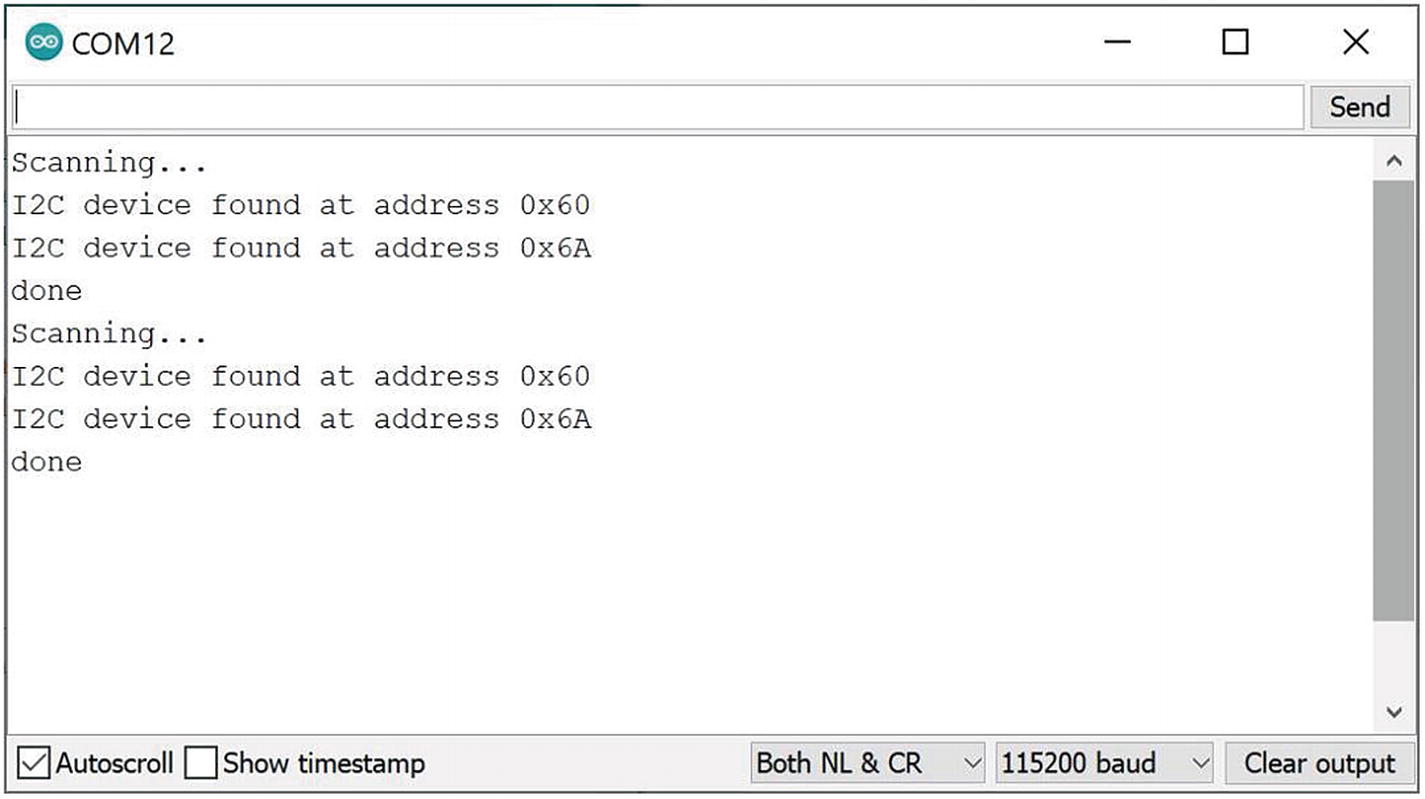
In Chapter 2, we learned about the I2C interface. We also perform a scan of the I2C address. You can run the i2c_scanner program from Chapter 2. Figure 3-2 shows a list of I2C addresses of I2C devices. The IMU sensor runs on 0x60 and x6A I2C addresses.
Figure 3-2
A list I2C addresses from sensor device-based I2C interface
In this chapter, we will explore the IMU sensor, LSM6DS3, on Arduino Nano 33 IoT. We access accelerator and gyroscope sensors from the Arduino program.
Set Up LSM6DS3 Library
To access the IMU sensor-based LSM6DS3 chip on Arduino Nano 33 IoT, we need to install the Arduino LSM6DS3 library. This library can be used to access the IMU sensor for accelerator and gyroscope sensors. We will use this library in this chapter. Details about the LSM6DS3 library can be read at this link, https://www.arduino.cc/en/Reference/ArduinoLSM6DS3.
To install the Arduino LSM6DS3 library, you can open Arduino software. Then, click the menu Sketch ➤ Include Library ➤ Manage Libraries, as shown in Figure 3-3.
Figure 3-3
Opening the Manage Libraries menu in Arduino software
After we click the Manage Libraries menu, we will obtain a Library Manager dialog, as shown in Figure 3-4. You can type arduino_lsm6ds3 in the search textbox. Then, you should see a list of libraries. You should also see the Arduino_LSM6DS3 library. In Figure 3-4 you can see the Arduino_LSM6DS3 library that is noted by a red arrow.
Figure 3-4
Installing the Arduino LSM6DS3 library
Click the Install button after you click the Arduino_LSM6DS3 library. Make sure your computer is connected to the Internet. After completing installation, we can access the IMU sensor on Arduino Nano 33 IoT.
Working with an Accelerator
The IMU sensor in Arduino Nano 33 IoT has an accelerator sensor. This sensor measures acceleration on x, y, and z coordinates. The sensor value ranges from -4 to 4. We will use the Arduino LSM6DS6 library to access the IMU accelerator sensor.
In general, we can start to use the LSM6DS6 library by calling IMU.begin(). Then, we can read the sensor value by calling the IMU.readAcceleration() function.
For the demo, we read the IMU accelerator on the Arduino Nano 33 IoT board. Then, we print the measurement result on the serial terminal. You can open Arduino software and write this complete program.
#include <Arduino_LSM6DS3.h>
void setup() {
Serial.begin(115200);
while (!Serial);
if (!IMU.begin()) {
Serial.println("Failed to initialize IMU!");
while (1);
}
Serial.print("Accelerometer sample rate = ");
Serial.print(IMU.accelerationSampleRate());
Serial.println(" Hz");
Serial.println();
Serial.println("Acceleration in G's");
Serial.println("X Y Z");
}
void loop() {
float x, y, z;
if (IMU.accelerationAvailable()) {
IMU.readAcceleration(x, y, z);
Serial.print(x);
Serial.print(' ');
Serial.print(y);
Serial.print(' ');
Serial.println(z);
}
}
Save this program as SimpleAccelerometer. Now you can compile and upload this program into Arduino Nano 33 IoT. We can see program output using the Serial Monitor. Change your board position or shake your board or move your board with certain speed so you have a measurement result on the serial terminal.
Figure 3-5 shows my program output for the SimpleAccelerometer program. You can see accelerator values for x, y, and z.
Figure 3-5
Program output from reading the IMU accelerator
How does it work?
First, we include the Arduino LSM6DS3 library in the Arduino program.
#include <Arduino_LSM6DS3.h>
We initialize the IMU sensor and the Serial object on the setup() function.
void setup() {
Serial.begin(115200);
while (!Serial);
if (!IMU.begin()) {
Serial.println("Failed to initialize IMU!");
while (1);
}
We also can print the current accelerator sample rate by calling the IMU.accelerationSampleRate() function on the serial terminal.
Serial.print("Accelerometer sample rate = ");
Serial.print(IMU.accelerationSampleRate());
Serial.println(" Hz");
Serial.println();
Serial.println("Acceleration in G's");
Serial.println("X Y Z");
On the loop() function, we read the accelerator sensor. We should check whether there is available accelerator sensor data by calling the IMU.acccelerationAvailable() function. If it’s available for sensor data, we can read the sensor data using the IMU.readAcceleration() function.
void loop() {
float x, y, z;
if (IMU.accelerationAvailable()) {
IMU.readAcceleration(x, y, z);
Then, we print the sensor data on the serial terminal.
Serial.print(x);
Serial.print(' ');
Serial.print(y);
Serial.print(' ');
Serial.println(z);
Working with Gyroscope
Gyroscope is a sensor to measure orientation and angular velocity. Arduino Nano 33 IoT has a built-in gyroscope sensor over the IMU LSM6DS3 sensor chip. We can access this sensor using the Arduino LSM6DS3 library.
For our demo, we read the gyroscope sensor using the Arduino LSM6DS3 library. Then, we print sensor data in the serial terminal. Open Arduino software and write this complete program.
#include <Arduino_LSM6DS3.h>
void setup() {
Serial.begin(9600);
while (!Serial);
if (!IMU.begin()) {
Serial.println("Failed to initialize IMU!");
while (1);
}
Serial.print("Gyroscope sample rate = ");
Serial.print(IMU.gyroscopeSampleRate());
Serial.println(" Hz");
Serial.println();
Serial.println("Gyroscope in degrees/second");
Serial.println("X Y Z");
}
void loop() {
float x, y, z;
if (IMU.gyroscopeAvailable()) {
IMU.readGyroscope(x, y, z);
Serial.print(x);
Serial.print(' ');
Serial.print(y);
Serial.print(' ');
Serial.println(z);
}
}
Save this program as SimpleGyroscope. Now you can compile and upload this program into Arduino Nano 33 IoT. We can see the program output using the Serial Monitor. Change your board orientation to see the change values on the Serial Monitor tool.
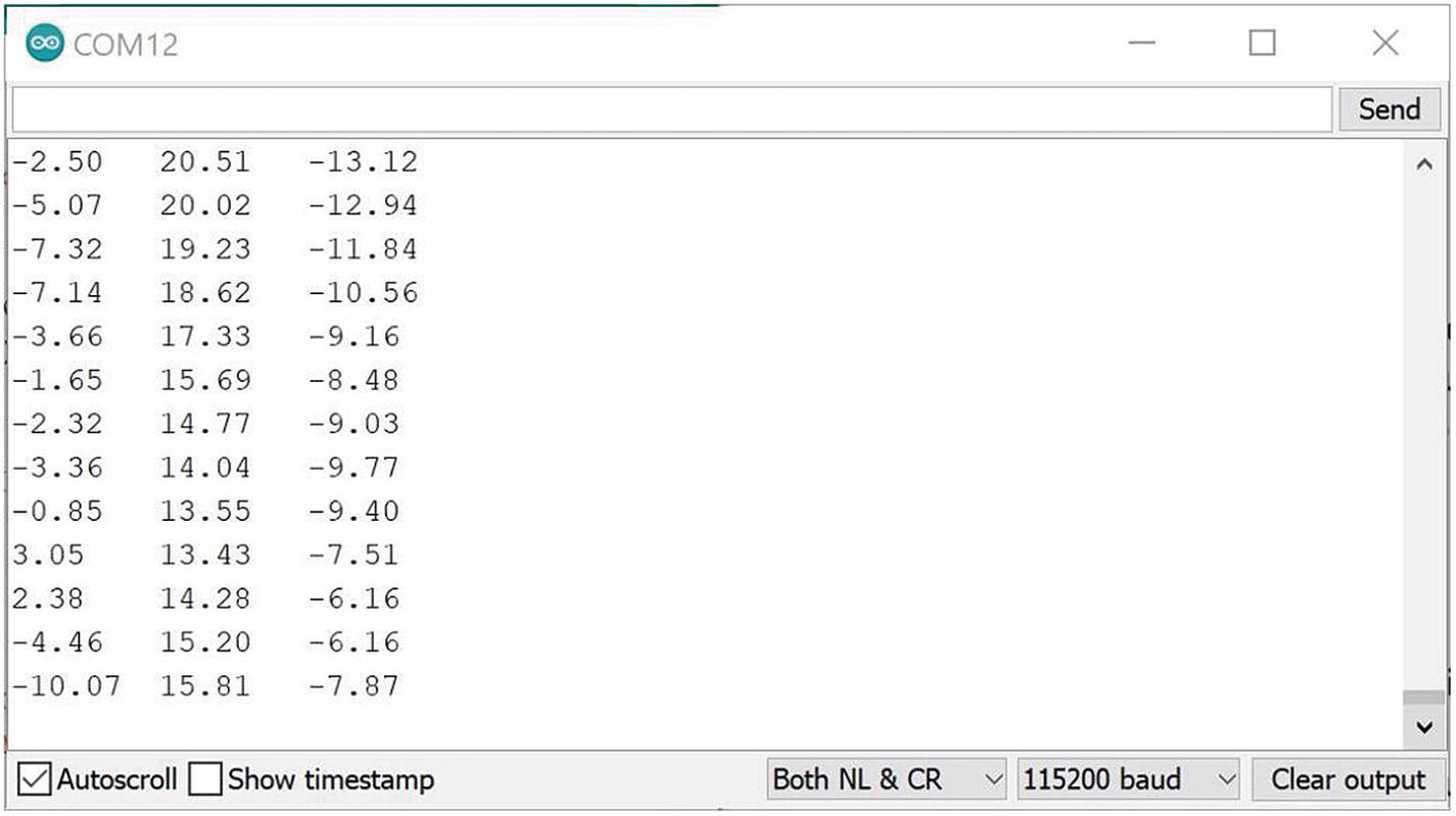
Figure 3-6 shows my program output for the SimpleGyroscope program. You can see gyroscope values for x, y, and z.
Figure 3-6
Program output from reading the gyroscope sensor
How does it work?
First, we include the Arduino LSM6DS3 library in the Arduino program.
#include <Arduino_LSM6DS3.h>
We initialize the IMU sensor to enable work with the gyroscope sensor and the Serial object on the setup() function.
void setup() {
Serial.begin(115200);
while (!Serial);
if (!IMU.begin()) {
Serial.println("Failed to initialize IMU!");
while (1);
}
We also can print the current gyroscope sample rate by calling the IMU.gyroscopeSampleRate() function on the serial terminal.
Serial.print("Gyroscope sample rate = ");
Serial.print(IMU.gyroscopeSampleRate());
Serial.println(" Hz");
Serial.println();
Serial.println("Gyroscope in degrees/second");
Serial.println("X Y Z");
On the loop() function, we read the gyroscope sensor. We should check whether there is available gyroscope sensor data by calling the IMU.gyroscopeAvailable() function. If it’s available for the Gyroscope sensor data, we can read sensor data using the IMU.readGyroscope() function.
void loop() {
float x, y, z;
if (IMU.gyroscopeAvailable()) {
IMU.readGyroscope(x, y, z);
Then, we print the sensor data on the serial terminal.
Serial.print(x);
Serial.print(' ');
Serial.print(y);
Serial.print(' ');
Serial.println(z);
This is the end of the project. You can practice by applying the IMU sensor in your projects.
Plotting Sensor Data
We can read sensor data from built-in sensor devices on Arduino Nano 33 IoT. In this section, we will plot our sensor using the Serial Plotter tool from Arduino. For testing, we will use previous projects that read the Gyroscope sensor.
You can open Arduino software. We initialize our Gyroscope sensor and serial communication on the setup() function. We set serial baudrate 115200 and initialize Gyroscope by calling the IMU.begin() function.
#include <Arduino_LSM6DS3.h>
void setup() {
Serial.begin(115200);
while (!Serial);
if (!IMU.begin()) {
Serial.println("Failed to initialize IMU!");
while (1);
}
}
On the loop() function, we read the Gyroscope sensor using IMU.readGyroscope(). First, we should check availability of sensor data by calling the IMU.gyroscopeAvailable() function. We store the Gyroscope sensor to x, y, and z variables.
void loop() {
float x, y, z;
if (IMU.gyroscopeAvailable()) {
IMU.readGyroscope(x, y, z);
To plot the Gyroscope sensor to the Serial Plotter tool, we can print sensor values with the “,” delimiter. For instance, we print x, y, and z sensor variables as follows.
Serial.print(x);
Serial.print(',');
Serial.print(y);
Serial.print(',');
Serial.println(z);
}
}
Now save this program as GyroscopePlotter program. Then, you can compile and upload this program in Arduino Nano 33 IoT.
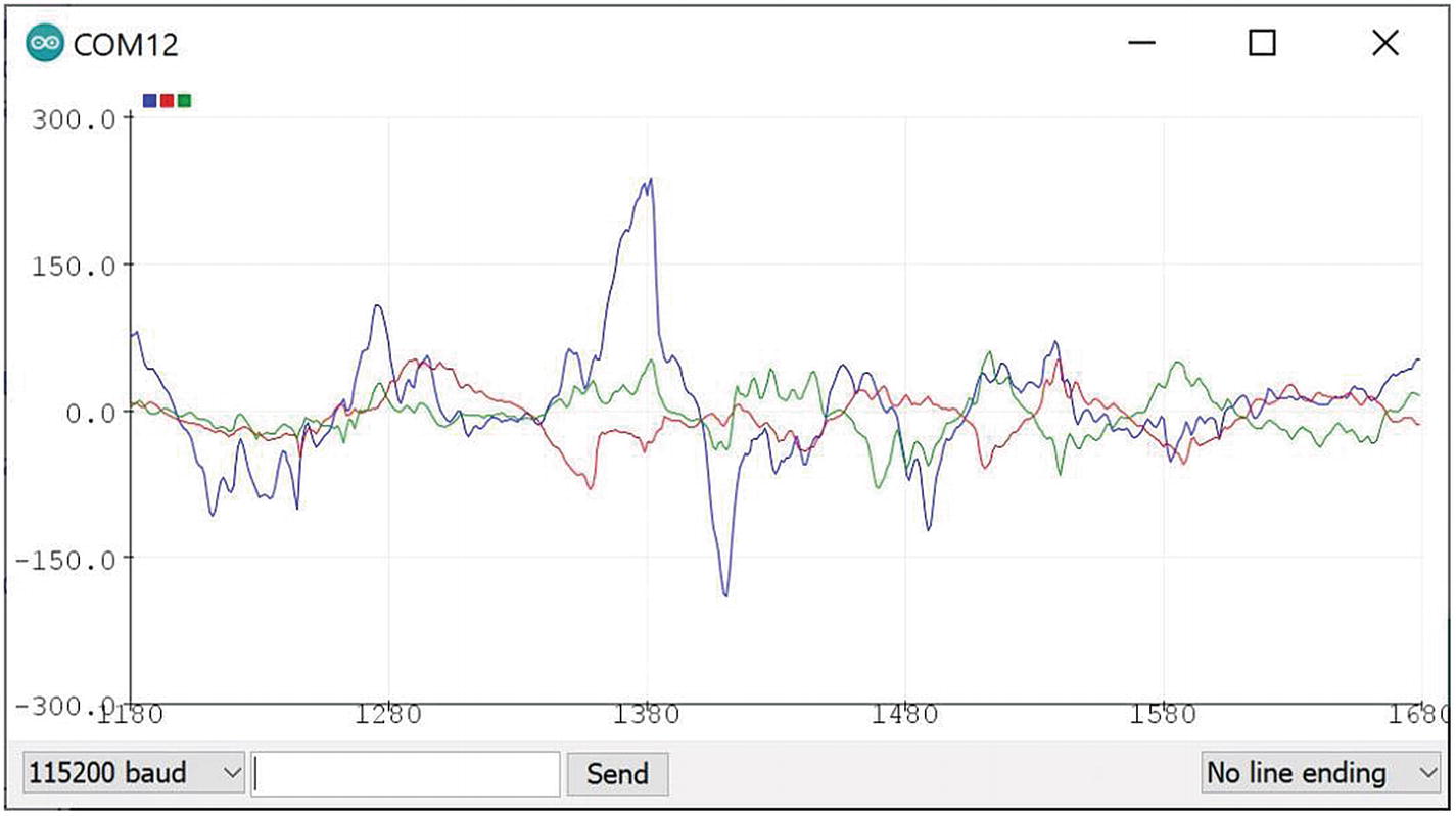
After uploading the program, you can open the Serial Plotter from the Tools menu in Arduino software. You should see sensor outputs on the Serial Plotter too. Figure 3-7 shows my program output from the GyroscopePlotter program.
Figure 3-7
Plotting the Gyroscope sensor on Serial Plotter
Displaying Sensor Data with Organic Light-Emitting Diode I2C Display
In this section, we want to display sensor data on an organic light-emitting diode (OLED) display. There are two interface models on OLED display: serial peripheral interface (SPI) and I2C. In this demo, we will use the OLED I2C display. You can buy any OLED I2C display module in a local electronic store. You can probably find it on Aliexpress or Alibaba.
For this demo, I use the OLED I2C display with 0.96 inch or 128 x 64 pixels. You can see my OLED I2C display in Figure 3-8.
Figure 3-8
OLED 0.96-inch I2C display
You can use any display size for the OLED I2C display. Next, we will wire the OLED I2C display for Arduino Nano 33 IoT.
Wiring for Arduino Nano 33 IoT and the OLED I2C Display
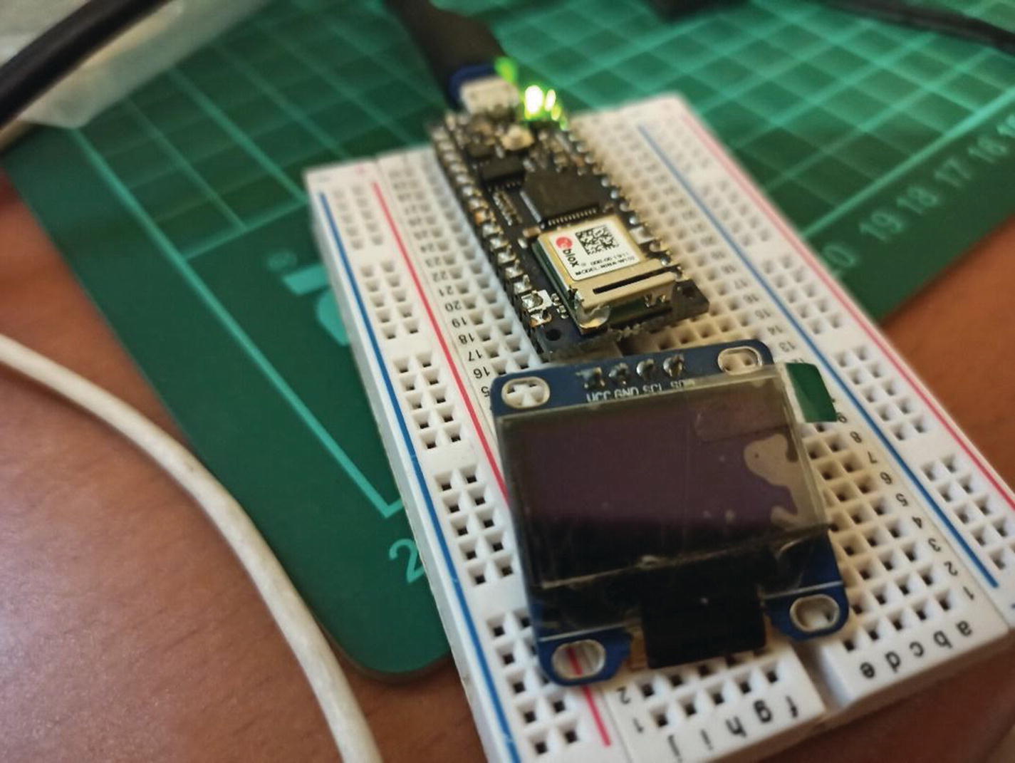
We use the OLED display with an I2C interface so we can connect this OLED display to Arduino Nano 33 IoT over I2C pins. You can see my wiring in Figure 3-9. You can perform this wiring as follows:
The OLED I2C display module serial data is connected to the Arduino A4 pin.
The OLED I2C display module serial clock is connected to the Arduino A5 pin.
The OLED I2C display module voltage common collector (VCC) is connected to Arduino 3.3V.
The OLED I2C display module ground (GND) is connected to the Arduino GND pin.
Figure 3-9
Wiring the OLED I2C display on Arduino Nano 33 IoT
Next, we can build the Arduino program for the OLED I2C display.
Checking the I2C Address of the OLED I2C Display
After we make wiring between the Arduino Nano 33 IoT and the OLED I2C display, we can use the i2c_scanner program from Chapter 2 to check the I2C address from devices. We want to know the I2C address from the OLED I2C display.
Load the i2c_scanner program into Arduino software. Then, compile and upload this program into Arduino Nano 33 IoT. After that, open the Serial Monitor tool. You should see three I2C addresses. Two of them are I2C built-in sensors on Arduino Nano 33 IoT. The rest is our OLED I2C display.
You can see my program output in Figure 3-10. You can see my OLED I2C display running on the 0x3C I2C address. Two I2C addresses, 0x60 and x6A, are I2C built-in sensors on Arduino Nano 33 IoT.
Figure 3-10
Detecting I2C addresses for the OLED I2C display
Next, we set up libraries in order to build programs for OLED I2C display on Arduino Nano 33 IoT.
Setting up the OLED I2C Display Library
To work with the OLED I2C display on Arduino, we need to install two of the following libraries from Adafruit:
We can install these libraries via Library Manager on Arduino software. Type Adafruit_SSD1306 and Adafruit GFX Library to install these libraries. Figure 3-11 shows Adafruit_SSD1306 library.
Figure 3-11
Adding libraries for the OLED I2C display
Install these libraries. You will probably be asked to install additional libraries to enable work with Adafruit_SSD1306 and Adafruit GFX library—for instance, Adafruit BusIO.
Testing the OLED I2C Display
After we installed the Adafruit_SSD1306 library, we can test our OLED I2C display. We can use program samples from Adafruit_SSD1306 library. You can find it in the menu File ➤ Examples ➤ Adafruit_SSD1306 ➤ ssd1306_128x64_i2c. After clicked, you should obtain codes as shown in Figure 3-12.
Figure 3-12
A program sample for the OLED I2C display
Next, we modify this program with the I2C address from our OLED I2C display. In the previous section, we had the 0x3C address for the OLED I2C display. Replace the I2C address display.begin() with 0x3C, as shown in Figure 3-12.
Now you can compile and upload this program to Arduino Nano 33 IoT. You should see some forms on the OLED I2C display. Figure 3-13 shows program output from ssd1306_128x64_i2c on the OLED I2C display with 128x64 pixels.
Figure 3-13
Running the ssd1306_128x64_i2c program on the OLED I2C display
If you can see display output with the ssd1306_128x64_i2c program, it means your OLED I2C display works. We will use this OLED to display sensor data.
If you don’t see display output, first, check the I2C address of your OLED I2C display. Then, make sure your OLED I2C displays with display size 128x64 pixels.
Displaying the Gyroscope Sensor
In this section, we will build the Arduino program to display the Gyroscope sensor for the OLED I2C display. We will use a program from the previous section to read the Gyroscope sensor.
Now we can open Arduino software and create a new program. We start by importing all required libraries for the OLED I2C display and the Gyroscope sensor.
#include <SPI.h>
#include <Wire.h>
#include <Adafruit_GFX.h>
#include <Adafruit_SSD1306.h>
#include <Arduino_LSM6DS3.h>
We define the OLED I2C display size. In this demo, I use 128x64 pixels. You can change its size based on your OLED module.
#define SCREEN_WIDTH 128
#define SCREEN_HEIGHT 64
Next, we configure Adafruit_SSD1306 with passing the I2C address of the OLED module and display size.
On the setup() function, we initialize serial communication, the Gyroscope sensor, and Adafruit_SSD1306.
void setup() {
Serial.begin(115200);
if (!IMU.begin()) {
Serial.println("Failed to initialize IMU!");
while (1);
}
if(!display.begin(SSD1306_SWITCHCAPVCC, 0x3C)) { // Address 0x3D for 128x64
Serial.println(F("SSD1306 allocation failed"));
for(;;); // Don't proceed, loop forever
}
After that, we test the OLED I2C display by calling display() for 2 seconds. Then, we clear the screen of the OLED display.
display.display();
delay(2000); // Pause for 2 seconds
// Clear the buffer
display.clearDisplay();
}
On the loop() function, we read the Gyroscope sensor. First, we check the sensor data with IMU.gyroscopeAvaliable(). If it’s available, we can read the sensor data using the IMU.readGyroscope() function. Store all the sensor data on the x, y, and z variables.
void loop() {
float x, y, z;
if (IMU.gyroscopeAvailable()) {
IMU.readGyroscope(x, y, z);
Next, we display sensor data on the OLED I2C display using the print() function. We also use setTextSize() to set font size.
display.clearDisplay();
display.setTextSize(1);
display.setTextColor(SSD1306_WHITE);
display.setCursor(0,0);
display.print("Gyroscope: X, Y, Z");
display.setTextSize(2);
display.setCursor(0,12);
display.print(String(x));
display.setCursor(0,30);
display.print(String(y));
display.setCursor(0,48);
display.print(String(z));
display.display();
Finally, we display the sensor data into serial terminal using the Serial.print() and Serial.println() functions.
Serial.print(x);
Serial.print(' ');
Serial.print(y);
Serial.print(' ');
Serial.println(z);
delay(300);
}
}
Save this program as OledSensor. Now you can compile and upload this program in Arduino Nano 33 IoT. You should see sensor data on the OLED I2C display, as shown in Figure 3-14.
Figure 3-14
Displaying the Gyroscope sensor on the OLED I2C display
You also can see program output on the Serial Monitor tool. You can see my program output in Figure 3-15.
Figure 3-15
Program output from OledSensor
This is the end of the chapter. You can practice by applying the IMU sensor in your projects.
Summary
You have learned how to access internal IMU sensors in Arduino Nano 33 IoT. We began by setting up the LSM6DS3 library. Then, we created Arduino programs to access accelerator and gyroscope sensors on Arduino Nano 33 IoT. Finally, we displayed sensor data on the Serial Plotter tool and OLED I2C display.
Next, we will learn how to access networks on Arduino Nano 33 IoT and make IoT programs.