
Chapter 2
Systems Engineering Fundamentals
There is no one theory that completely defines systems engineering (SE). Specifically, it is a branch of engineering that does not go back to physical first principles. SE is not simply a planning process to define and execute the job at hand. As the title of this book suggests, systems engineering is one piece of the total topic to be discussed. SE, however, is considered only in a loose sense, and the focus of the book is on the analysis and trade space associated with producing a balanced air and missile defense system (AMDS). SE will be treated first as an outline to accomplish the true purpose of the book. This is not a theoretical treatment of SE nor is it an exhaustive practical treatment. Accordingly, this book is not advocating for, nor arguing against, any specific SE formula. There are many examples [1–8] to choose from. It is advocated that you simply need to have one and that you try to keep it as simple as possible while not letting the details of the program slip into the cracks. Certainly, if you are spending more money on planning and executing the program than on designing, testing, deploying, and sustaining it, you have some issues to address. You should, however, be allocating about 30% of your resources to planning and requirements development.
There are more definitions for SE than could possibly fit in this book. Some have been found to be fundamentally identical and others have little in common with the rest. To avoid adding superfluous material, the definition that is most compatible with the topic of air and missile defense is adopted with some added descriptors. Systems engineering can be defined as “a process that is comprised of a number of activities that will assist in the definition of the requirements for a system, transform these requirements into a system through design and development efforts, and provide for the operations and sustainment of the system in its operational environment” [1]. The systems engineer is the one who is responsible for the program definition and who puts the plan of action into motion. The systems engineer has three roles: the technical roles of an architect, designer, integrator, and tester; the role of a systems or technical manager; and the role of a production engineer. To achieve success, the systems engineer is required to employ both artistic and scientific engineering skills. An experienced systems engineer develops instincts for identifying and focusing a team’s efforts on activities that will ultimately achieve an optimized or balanced design while accounting for lifecycle considerations. The art of systems engineering takes the form of developing the right set of design alternatives and options and then developing the necessary trade studies that will help the systems engineer eliminate all but the best sets and combinations of alternatives from which an investment decision(s) can be made.
Why is systems engineering important? The purpose of SE is to establish a repeatable, traceable, and verifiable methodology to produce systems and products to facilitate verification, validation, and accreditation (VV&A) with an improvement in cost and schedule while minimizing the risks associated with engineering endeavors. SE includes configuration control management and lifecycle sustainability and maintainability.
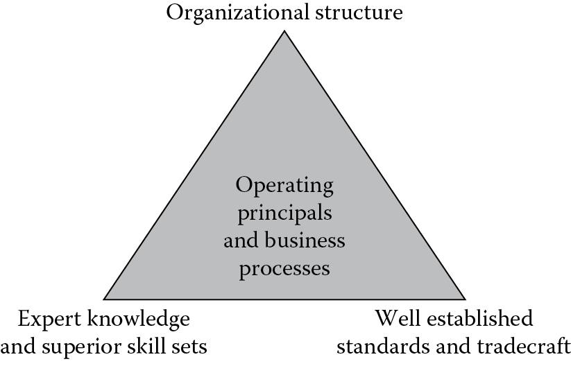
Systems engineering starts by defining a standard framework within a common lifecycle process that can be applied to any system regardless of the scope or scale of the project. Numerous system engineering frameworks have been proposed. Hall [1,2] is widely quoted either implicitly or explicitly throughout the systems engineering literature [3–6]. Hall proposed that systems engineering has three major dimensions that make up the Hall morphological box of systems engineering: time, logic, and professional disciplines. Practically, this decomposition is incomplete and premature. NASA [7] proposes the morphological framework to be a three component model. Here we believe there is a fourth component and a slighted modified third component. This systems engineering framework recommended for practice is shown in Figure 2.1, which shows that systems engineering can be thought of as vectors to achieving one’s goals and objectives. A program requires four component to succeed. The first component is a well thought out organizational structure or Integrated Product Team (IPT) structure. This component is the most important. Without the right organizational structure or set of structures, the program has little chance of succeeding. The second component is to populate the lead positions in the IPT (organizational structure) with experts in their field and having superior skill sets demonstrated by achievement. Third, your program needs to have established engineering standards and tradecraft practices communicated and understood throughout the team. The fourth component is to have well established operating principals and business practices through your program. The operating principals and business process are at the center of the pyramid to communicate that the other three components alignment relies on standardized operating principals and business practices.
The concept and process essentially includes the layout of the SE plan that lends itself to VV&A and is intended to maintain consistency, repeatability, and traceability throughout the program’s lifecycle. Tools and methods apply to defining tradecraft and will subsequently contribute to VV&A, configuration control, traceability, and repeatability of results. Knowledge and skills of the workforce call for the placement of highly trained and experienced engineers with appropriate backgrounds in leadership positions and, most notably, skills in running integrated product teams (IPTs). A balance between a solid government team, a contractor, and laboratory team members must also be maintained. The program should be structured such that the manager is able to matrix talent in/out of the IPTs as required.
The components of a standard systems engineering process that can be applied to any project regardless of scope and scale include the following:
- Well-defined goals and expectations (qualitative)
- Performance objectives or measures of effectiveness (quantitative)
- A concept of operations (CONOPS) that includes the way the system is intended to operate, and the way the design, test, manufacturing, and deployment process is intended to operate
- Requirements definitions that include functional, performance, and interface requirements
- Defined constraints that include itemized cost, schedule, policy, logistics, human factors, and technology
- Risk assessments that are itemized and time dependent with evolving mitigation plan
- The program’s milestone objectives and lifecycle reviews
To accomplish these tasks, the SE process should be decomposed into four teams or strategies: technical management, systems architectural design, technical evaluation, and product realization. The technical management responsibilities include stakeholder and customer interactions; requirements, constraints, risk, configuration control management; programmatics; architectural and technical evaluation processes; planning decisions; program reviews; and the development of management documentation that includes the systems engineering management plan (SEMP). The systems architectural design responsibilities include requirements development and flow down; implementation of the design process and the development of the design solutions; data development; risk analysis and identification; and the development of design documentation including program review materials. The technical evaluation responsibilities include the development of and adherence to the systems performance analysis process; the requirements verification process; the design and end product validation process; and the development of the performance evaluation documentation packages. The product realization responsibilities include the formulation of the design-to-production process; the establishment of the manufacturing processes and procedures; and the development of deployment and training plans and procedures.
The next part of organizing the program should include structuring the program’s milestone objectives and reviews. Each program will have to decide how many and what milestone reviews are necessary or desirable. It is important to note that reviews should not/do not end when the product is deployed.
A minimum set of timed reviews should include a systems requirements review (SRR), a preliminary design review (PDR), a critical design review (CDR), a test readiness review (TRR), an operational readiness review (ORR), an operational capability review (OCR), lifecycle assessment reviews (LAR), and a retirement and disposal review (RDR). The reviews need to be set up to include specific program accomplishments, transition decisions, and completed documentation. These reviews occur on a timeline and are embedded in a schedule. Normally, the milestone reviews are mapped to program phases that establish the entire program timeline from conception to birth to retirement (pre-cradle to grave).
The systems engineering plan encompasses the seven phases as follows:
- Pre–Phase A: Project Definition
- Phase A: Systems Requirements
- Phase B: Preliminary Design
- Phase C: Detailed Design
- Phase D: Engineering, Manufacturing, Development; Integration and Test
- Phase E: Operations and Sustainment
- Phase F: Retirements and Disposal
These seven phases are defined by their purpose, activity, documentation, and the culminating program review(s). A timeline (schedule) and cost must be established and correlated with specific activities. Beyond pre–Phase A, recurring risk assessment and risk mitigation should take place. A management plan diagram can be constructed, which will identify the phase, the phase purpose, the associated primary milestone review, entry criteria associated with the phase activities, documentation requirements, and schedule requirements. Each management plan will have an associated cost and manpower requirement that needs to be secured, authorized, and funded.
2.1 Pre–Phase A
A notional pre–Phase A management plan is shown in Figure 2.2. Each of the program strategy teams is put into action starting in pre–Phase A. The management team manages this matrix, the internal processes, documentation, costs, constraints, and risks. The other teams execute their jobs as described earlier. This phase typically consists of the government team and laboratories, and should include prime contractor involvement. The prime contractors are truly the only ones who know how to engineer, manufacture, and deploy products. Your prime contractor and laboratory support teams should have already been established for planning purposes. The objective of this phase is to develop and implement the program plan. You cannot expect to accomplish practical objectives without their involvement upfront. Pre–Phase A will include defining the mission need in terms of realizable goals and objectives, concept systems and architectures, draft measures of effectiveness/performance, and systems top-level requirements (TLRs). In addition, stakeholders and their expectations are clearly identified; technology development needs are identified; and trade studies are identified and defined in detail. Iteration between these activities is expected to fully and accurately complete pre–Phase A. Verifying and validating (to be discussed in Chapter 4) results are necessary in each phase.
|
Entry Criteria/Inputs |
Pre–Phase A |
||
|
Develop and Implement the Program Plan |
|||
|
Project Readiness Review |
|||
|
Activity |
Documentation |
Timeline |
|
|
Mission need |
Translate MNS into program objectives |
Top-level requirements document |
Months |
|
Authorizations/ funding |
Define program objective measures of effectiveness |
Months |
|
|
Define top-level requirements |
Months |
||
|
ID/Define constraints and risks |
Systems Engineering Master Plan (SEMP) |
Months |
|
|
ID/Define SE processes/methods |
Months |
||
|
ID/Define knowledge, skills, abilities, requirements |
Months |
||
|
Define work breakdown structure |
Months |
||
|
Develop requests for proposals |
RFPs |
Months to a year or more |
|
Pre–Phase A management plan.
The final pre–Phase A output is likely to be a project readiness review (PRR). A SEMP outline template of an SEMP is provided in Appendix 2A. The SEMP is essentially a road map to navigate through the program, which will be updated in the next two phases. Your prime contractor and laboratory support teams should have already been established for planning purposes. Prior to developing a WBS and completing the SEMP the program IPT structure must be in place. However, executing the program may require additional or different contractors. This fact will require you to send out a round of requests for proposals (RFPs) at the completion of pre–Phase A in an effort to hire the right contractor teams for the effort. The RFPs will usually be answered within a 30- to 45-day period, and the technical evaluation team will need to recommend a selection to the management team. The selection process may take months.
2.2 Phase A
A notional Phase A management plan is shown in Figure 2.3. This phase typically consists of the government team and laboratories and should, as in pre–Phase A, include prime contractors’ involvement. The objective of this phase is to fully develop a baseline mission concept and assemble the systems requirements document (SRD). The final output is the systems requirements review (SRR).
|
Entry Criteria/Inputs |
Systems Requirement Document |
||
|
Systems Requirements Review |
|||
|
Activity |
Documentation |
Timeline |
|
|
Authorizations/ funding |
CONOPS |
Systems requirements document |
Months |
|
SEMP |
Top-level systems architecture |
Months |
|
|
TLR |
Requirements flow down |
Months |
|
|
SER |
Configuration control management plan |
Update SEMP/WBS |
Weeks to a month |
|
Validation, verification, and accreditation plan |
Weeks to a month |
||
|
Data development plan |
Weeks to a month |
||
|
EMD plan |
Months |
||
|
Request for proposals |
RFPs |
Months |
|
Phase A management plan.
Phase A develops and refines feasible concepts and finalizes goals and objectives. Some concepts may be eliminated while others may be added. Systems and architectures, and measures of effectiveness/performance are refined. The TLR document is updated and approved. At this point, technology development requirements and a risk assessment are developed for each viable concept that, in turn, become part of the set of trade studies. Trade studies are executed with the purpose of eliminating bad concepts and ranking good concepts. Trade studies focus on evaluating technical, schedule, and cost objectives. The result of the trade studies includes a system and architectural baseline; functional allocations to hardware, software, and other resources; and new plans are developed. The SEMP now contains more details of the associated management plans and will be updated again in the next phase. You will be required to send out your final RFP sets. The objective here has to expeditiously send out the RFPs and then to receive, evaluate, and select contractors from the proposal responses. In some cases, the government will use the PDR in Phase B to down-select the final contract awards. In this case, the competing contractors down-selected from the pre–Phase A RFP process are funded to produce a preliminary design for review based on the documentation prepared in pre–Phase A and Phase A. Whoever came up with this concept should be considered a genius. This process allows the government to actually see the contractors in action. It provides the government with multiple design choices, which subsequently is a risk reduction activity in itself. Moreover, in the event the selected contractor slips, the government has a fallback position with the runner-up contractor. The added cost for funding multiple PDR phase competitors essentially buys down program risk while allowing multiple contractors to develop new capabilities that would benefit them and the government in follow-on competition.
2.3 Phase B
A notional Phase B management plan is shown in Figure 2.4. This phase typically consists of the government team and laboratories, and the focus is on the prime contractor developing a preliminary design for review. The objective of this phase is to produce a system definition with enough detail to baseline a design for EMD and capable of meeting the mission need. The final output is the preliminary design review (PDR). Phase B includes design and performance requirements flow down to subordinate systems and subsystems within the architecture. Interface requirements are added to the SRD. Trade studies defined in Phase A continue as required to refine concepts and are input to newly defined design studies aimed at allocating capability and performance to systems and subsystems. The design studies include interfaces, which include hardware, software, and communication within the architecture, systems, and subsystems. Verification and validation plans are developed. Finally, all of the products developed in Phase A are updated and reapproved. Verification and validation accompany the results of trade studies. An updated SRD, system design documents (SDD), a verification assessment, and an updated EMD plan are presented for approval at the PDR. The SRD is now in lockdown. However, requirement changes beyond this point are a normal and expected occurrence. The difference is that a formal procedure and approval by configuration control management (CCM) must take place. Any proposed changes to the requirements will usually cause a cost and schedule impact to the program. If requirement changes are inevitable (requirements creep), it usually means that cost and schedule increases should be expected. Technical interchange meetings (TIMs) between all or subset IPT members are a requirement during this phase. TIMs are also highly encouraged in the earlier stages, but are shown specifically in the Phase B management plan because of the critical nature of early and continuous communication and resolution of issues between IPT members when the preliminary design is being developed.

2.4 Phases C–F
Management plans for Phases C–F are assembled in the same manner as shown earlier, but the details are different. These program phases are, however, beyond the scope of this book and are not presented. The important lesson here is that although macro schedules and plans are required, breaking your program down into small chunks is more manageable. The larger and more complex the program, the more essential it becomes to break it into smaller pieces. In turn, as you subdivide the system into smaller pieces to manage interfaces, interoperability solutions become an increasingly important design consideration and attention.
Air and missile defense systems (AMDS) are complex engineering undertakings composed of many systems within systems and subsystems within systems. AMD subsystems have many components and those components interact in complex ways with each other and the environments surrounding them. The interactions are complex and can lead to unpredictable and sometimes unexpected results. Essentially, AMD systems engineering is rocket science and needs to be treated accordingly.
Following good systems engineering practices will enhance the likelihood of achieving optimized performance and ultimately success in satisfying program objectives and within cost and schedule. Systems engineering employed properly will aide to produce a balanced design despite, at times, being faced with opposing and conflicting physical, fiscal, and time constraints.
Each phase discussed earlier has three common and primary focused activities that are solved iteratively. They are requirements development and management, concept development, and architectural design solution development. These activities are tied together with rigorous verification and validation activities and occur in a cyclical fashion between the activities. The iterative spiral moves from one phase to the next progressively improving the system performance.
The NASA Systems Engineering Handbook, SP-6105 [7], states, “The objective of systems engineering is to see to it that the system is designed, built, and operated so that it accomplishes its purpose in the most cost-effective way possible, considering performance, cost, schedule, and risk.” Figure 2.5 provides a process to follow to help achieve a successful SRR that will enable these objectives being met.

Objectives and constraints are derived from the mission need and stakeholder expectations and documented. Objectives and constraints are met during each phase by defining and executing trade studies, conducting design and performance analysis, and verifying and validating results in an appropriate way for each phase. The iteration process is executed until an “optimal solution” is achieved. Optimal is the point at which the objectives and constraints are satisfied such that there is diminishing improvement in cost, schedule, and risk with additional iterations.
The three major functions that the book focuses in terms of air and missile defense systems engineering include concept-of-operations development, architecture and design development, and requirements development and analysis.
2.5 Concept-of-Operations Development
The concept of operations (CONOPS) describes the mission and how it may be accomplished. Multiple CONOPS are preferred in the beginning stages and are winnowed down to either a single or single set of CONOPS. The CONOPS is a narrative accompanied by diagrams, charts, and graphics to describe a proposed approach to solving the problem at hand. The problem is defined in terms of mission need, goals, objectives, and expectations. CONOPS is the first definition of the solution architecture. Moreover, the CONOPS will act as a tool for verification, mission planning, and requirements development and management.
Once the AMD problem is defined, the CONOPS will cover but is not limited to the following topics:
- The mission description in terms of the problem being solved
- A list of major functional requirements that need to be achieved to solve the defined problem
- A list and description of major assets considered in the solutions architecture
- A mapping of functional requirements to assets
- A list of performance metrics, both qualitatively and quantitatively, that are necessary to declare success or a level of success
- An engineering description of how the assets will perform the assigned functions including performance predictions and timelines
- A technology readiness description for achieving each functional requirement, these include technology challenges, and hurdles
- A listing and description of issues and concerns ranging from logistics, interoperability, communications, coordination, and problem identification
The CONOPS is probably not the place to address fiscal and schedule issues. It should be a source for predicting cost and schedule, which needs to be placed in the SEMP. The CONOPS needs to react iteratively to constraints brought about by schedule and cost concerns but should be independent from them to ensure that achievable technical solutions are being proposed and sought. The purpose is not to solve cost and schedule issues. It is best to not pursue the program at all if either cost or schedule prohibits a reasonable solution.
2.6 Product Architecture
Architectural design consists of engineering flow diagrams depicting functionality, interfaces, links, and communication. The product also includes graphics and technical descriptions addressing performance metrics. Once the CONOPS is produced, the objective is to produce the architecture of systems and subsystems that accomplish the CONOPS stated objectives.
Architecture is formally the style and method in which something is designed and constructed. In architecture, the structure of the components, their interrelationships, and the principles governing their evolution over the systems lifecycle are determined. The architecture is verified against the mission objective(s) and the CONOPS.
The AMDS architecture solution, most likely to evolve, is referred to as a system-of-systems (SOS) architecture or a family-of-systems (FOS) architecture. The SOS architecture according to Sage [3,4] has five principal characteristics and is composed of multiple independent systems able to achieve stated objectives on their own; the multiple systems are managed independently; they are spatially removed from one another; they develop in an evolutionary manner or spirally; and finally, the SOS has what Sage refers to as “emergent behavior.” The measurement of the SOS architecture effectiveness includes measures of interoperability when defining the initial measures of effectiveness (MOE).
2.7 Requirement-Driven Acquisitions
The requirements definition process can determine the success or failure of a program. As such, it is imperative that the requirements definition processes evolve, be iterative, and involve the team at large. Moreover, the requirements must state what is to be achieved and not how it is to be achieved. Bureaucracies enjoy central planning and control, and without exception fail because they always dictate not only what but how objectives are to be achieved.
The purpose of requirements is to identify and communicate what functions are to be performed and then specify how well each component, subsystem, element, and system within the system must perform. The mission need statement (MNS) is the highest-level requirement definition and should identify a problem, the objective to be achieved, and a statement on the performance that defines mission success. The MNS is satisfied when activity produces a system that will solve the problem with the performance specified.
The design requirements are the manifestation of transforming the mission need, stakeholder expectations, and constraints into a set of executable statements used to define and develop a design solution that can be verified and validated. The design requirements communicate what functions a system must perform and how well it must perform them. These requirements are organized into a hierarchy, which flows down through the systems of interest and are typically shown in the document tree. The design requirements development process is recursively increasing in detail through each cycle and layer of the design process. Design requirements are used to develop a description of all inputs, outputs, and their relationships. Moreover, design requirements must be written in a verifiable manner.
The top-level requirements (TLR) document must include the measures of effectiveness (MOEs) for the functional assets that are required, the performance required of those assets to achieve the MOEs, and the interfaces required to achieve functionality and meet the MOEs. The TLR and the MOEs are verified against the MNS, expectations, and the program constraints. The flow down requirements are verified against the TLR and MOEs.
One additional note of importance is that constraints such as cost, schedule, and policy, among other things, are embedded in the design requirements definition process. Therefore, they are part of the trade space when defining program design requirements. Cost and schedule constraints become design performance parameters. There is no reason to develop a solution to a problem that cannot be bought, or is only available, after it is needed.
Next, understanding how “corporate” policy will affect your design or design process is essential. For example, if you are encumbered in a policy that dictates a solution to the problem you are charged with solving, it is much better to give up before you start and search for a new problem to work on. Unfortunately, policy may limit your access to resources or possibly slow down your access to resources. This in turn can cause schedule increases, will most likely drive up cost, and will possibly prohibit a more efficient, or elegant solution. These types of policy issues are usually confronted in government or in large private companies or possibly at the national level. Regardless, they need to be recognized, identified, and defined within the phases of the requirements process and dealt with early in the program.
There are three requirements components necessary to quantify the system design. These three requirements define the program and are iteratively solved during each phase of the program.
Initially, the functional/operational requirement is produced. Functional/operational requirements identify and define what function(s) must be performed. This activity follows the specifications provided in the MNS. For example, the MNS: Our military forces need to destroy all hostile cruise missiles in flight before they reach their intended targets, is a stated mission need with performance requirements that need to be satisfied. The first part of this process is to define the metrics associated with accomplishing the MNS. The metrics may also be called the cornerstones or measures of effectiveness (MOEs) of your system. The cornerstones need to define What, When, Where, and How to achieve the mission. It is also important to define Why the mission is to be achieved. Good examples of performance metrics are the Aegis cornerstones developed by the U.S. Navy [9]. The first part of these cornerstones, the What, is the defined sequence: Detect, Control, Engage. The When, How, and Where are listed as follows:
- Reaction time—How
- Firepower—How
- Electronic countermeasure (ECM) and environmental resistance—When
- Continuous availability—When
- Area coverage—Where
The cornerstones are discussed later in the book.
These critical metrics are necessary to begin the functional requirements analysis to identify and define the functions that need to be performed to produce a system (or a system of system—SOS) that will achieve the stated objective with the specified performance requirement. When this trade-space analysis is completed, the functions are allocated to systems in the broad sense. Constraints and risks are identified and defined, and the CONOPS is produced, documented, and verified against the MNS and the specified performance objective.
The next requirement set needed is the design performance requirements. This is achieved by a trade-space analysis that is referred to as the systems performance requirements analysis. During this analysis process, an engineering balancing act is performed to distribute the responsibility for achieving the MOEs derived from your MNS objective with the specified performance using the systems where the required functions were allocated. Once completed, a systems requirements document (SRD) is developed, where the associated constraints and risks are also identified and maintained.
The next fundamental sets of requirements to develop are the interface and integration requirements. Interface requirements begin to develop during the PDR Phase B by conducting the appropriate trade-space analysis. System alternatives are selected in this design trade-space analysis where integration across systems is analyzed as part of the approach to determine the appropriate systems required to reach performance, cost, and schedule objectives. Once completed, an architectural design can be developed, and the associated constraints and risks are identified and documented. It is in the interface and integration requirements development process that interoperability issues are identified and derived requirements are developed to address those issues.
Each of these requirements components has associated constraints that must accompany their development. The requirements bundle is developed in a hierarchy flow decomposed into the three main components and become more detailed as the design and development process progress. Shared requirements across elements may exist and will be stated within the requirements breakdown wherever they exist. In Phase A, the systems requirements document (SRD) contains all three requirement types. In Phase B, the requirements have been flowed down into detailed specifications that allow a detailed design that satisfies the Phase A requirements to be built in Phase C.
The SRD will contain the top-level requirements and also specify the mission success criteria. The natural requirements flow will have the performance requirements following each functional requirement. Interface and integration requirements then specify how the elements interoperate by specifying their connectivity and are followed by interface performance requirements. The performance requirements have to be written and communicated in a verifiable manner.
2.8 Verification and Validation
Verification and validation are accomplished during each cycle of the design and development and for each segment, system, subsystem, element, and component to ensure the system meets the required mission objectives.
Essentially, verification addresses whether or not the design satisfies the requirements. Each of the major system elements, CONOPS, and the architectural design are verified against the requirements and must be consistent in solving the objective problem. Verification continues throughout the design and development process in a sequential manner. CONOPS is verified against the mission objective; the architectural design is verified against the CONOPS.
Validation is usually defined by ensuring that the objective system is built correctly. This includes analyzing, inspecting and testing, and simulating the system prototype against real-world data to accomplish validation. In the case of an AMDS, it should be tested and simulated in a manner that represents the way it is intended to fight. This requires end-to-end testing and simulating, including all input items, interfaces, and performance requirement emulations. Expected and unexpected variations in the environment and intended target sets need to be explored. Often, it is not possible to accomplish such extensive testing in pure hardware. Simulations become more important when the system and the problem become more sophisticated. In many cases, simulation may be the only means to validate the design that leads to an entirely new program of modeling and simulation that should be handled in a parallel manner to the systems development and testing against real-world data whenever possible. To build and test complex and sophisticated simulations has now become an inherent requirement for AMDS engineering. This not only includes a digital representation of your system but a commensurately complex digital representation of the intended targets and the associated environments. This is no small undertaking, and it will be a necessary part of your budget.
2A Appendix: Systems Engineering Management Plan
2A.1 Background
The systems engineering effort begins with the pre–Phase A concept study clearly identifying and communicating the program objectives. The systems engineering management plan (SEMP) is the foundation document communicating technical, engineering, and management activities for the program. The SEMP is generated during milestone Phase A, and baselined in Phase B. The SEMP should be updated as necessary when major project changes occur. The details of schedule, work flow, and the order of activities should be continuously updated as part of ongoing planning. An SEMP is prepared to address the complete milestone execution of the program. More specifically, the purpose of the SEMP is to communicate the technical and management road map by addressing technical design and development approach, process, integration, test and evaluation, and interfaces. SEMP documentation and approval serves as an agreement within the program of how the technical work will be conducted. The program manager usually assigns the SEMP responsibility to the systems engineer or the technical equivalent. The technical IPT leads work with the systems engineer and program manager to contribute, review the content, and obtain concurrences as necessary.
2A.2 SEMP Outline
2A.2.1 Introduction
The objective of systems engineering is to see that the system is designed, built, and operated so that it accomplishes the intended mission need and expectations in the most cost-effective way possible, considering performance, cost, schedule, and risk. The SEMP provides an end-to-end road map to accomplish this objective.
2A.2.1.1 Program Purpose
The program purpose is contained in the Mission Needs Statement (MNS). The MNS is a stated mission need with performance requirements that need to be satisfied.
2A.2.1.2 Program Mission Overview
Clearly, one should describe and document the mission objectives to ensure that the program team is working toward a common goal. The program objectives and any newly evolved objectives form the basis for performing the mission, and they need to be clearly defined and articulated. The program constraints, appropriate to the mission, are also captured and used to verify the mission design.
2A.2.1.3 System Concept-of-Operations Overview
The CONOPS is initially developed as a draft concept during pre–Phase A, with refinement throughout the lifecycle, until the flight operations plan is completed in Phase D. The outcome and decisions for key operations concept trade studies and optimizations should be documented. Trade studies and analyses are used to demonstrate that the operations concept will meet the mission requirements including cost and schedule and is consistent with the architecture and design. The CONOPS is verified against the TLR document including mission objectives. The CONOPS should be used to conduct requirements identification, flow down, and management, leading to the requirements used to generate the architecture and design.
2A.3 Integrated Product Team Structure and Responsibilities
2A.3.1 Technical Management
Define the systems engineering organizational chart with roles and responsibilities. The program manager should assign a chief or lead system engineer. The program manager and the systems engineer should develop the plan for the systems engineering effort and establish a system engineering team along with roles and responsibilities. This plan, along with the roles and responsibilities, are captured in this section. The systems engineer coordinates the efforts of the systems engineering team and has the responsibility for the systems engineering functions and products for the overall program. Specific duties and responsibilities are delegated by the systems engineer with the program managers’ approval to other members of the system engineering team and are captured here. Communication protocols between the team and the technical management are established here. Coordination protocol requirements are established here. The program manager makes decisions that maintain a balance between technical and programmatic performance.
2A.3.2 The Development of the Architectural Design Solution
The architectural design solution is first generated in pre–Phase A and defined and refined until the end of Phase B at the PDR. Initially, the architecture should start out as functional or logical blocks. As the design matures, the architecture should mirror the physical product breakdown structure (PBS). Once block and flow diagrams and interfaces are defined, then detailed design (Phase C) can proceed, with minimal risk of a major change induced by an architectural block diagram change. The architectural design solution should decompose the total system into its major parts to form the hierarchy for lower-level interfaces and specifications. The major parts of a system include the separate subsystems and boxes and their embedded hardware and software functions. The major goal of AMD systems engineering is coordinating the engineering trade studies, design, and development of an architectural solution that meets the requirements, is consistent with the CONOPS, operates in the mission environment, and can be developed on schedule and within cost. The SEMP should identify the technical means by which the architectural design solution will evolve and be documented throughout the team. Typically, block and signal flow diagrams are the primary means for documenting and communicating the architectural solution and designs to the team.
2A.3.3 Product Development
Production typically involves a different set of IPTs compared to any of the previous development phases. These IPTs as well as their technical management structure, and roles and responsibilities need to be defined.
2A.4 The Milestone Review Process
The project lifecycle is defined as a set of phases: formulation, approval, and implementation. The SEMP defines systems engineering phases that can be defined as pre–Phase A, Phase A, Phase B, Phase C/D, and Phase E/F terminology. Each systems engineering phase consists of functions and a workflow, which produce the products needed for the completion of the phase. The mission review is the verifying event for the phase and results in a revised mission baseline. The lifecycle accommodates the objective of systems engineering by considering implementation alternatives in Phase A, completing a preliminary design and verifying that the right system has been designed in Phase B, performing a detailed design and verifying that the system is designed correctly in Phase C, building and validating the system in Phase D, and operating and disposing of it in Phases E and F.
2A.5 Requirements Identification and Analysis Process
Requirements communicate what functions a system must perform and how well it must perform them. They describe the interfaces a system must meet. Requirements should be organized into a hierarchy that flows down through the systems of interest. The levels of requirements are typically shown in a document tree. The mission level-1 requirements, usually defined in the project plan, define mission success criteria and serve as the top level for the requirements hierarchy. Some of the items that need to be defined in the SEMP are listed in Sections 2A.5.1 and 2A.5.2.
2A.5.1 Requirements Identification
Document the requirements appropriate to the complexity of the system element. Define who develops the requirements hierarchy and who is responsible for each part of the hierarchy. Define what format is planned and what tools if any are used for documenting and tracking the requirements. Define when requirements identification is due and when formal configuration control is expected to start. Functional requirements describe what the system must do. Describe how to identify functional requirements. Performance requirements are attached underneath their respective functional requirement. Performance requirements describe and document how well the function needs to be performed. Performance requirements are written in a verifiable manner. Describe how to identify performance requirements. Requirements should specify the interfaces or reference configured interface specifications. Interfaces and ICD requirements are planned interfaces to be included. Describe how to identify interface requirements.
2A.5.2 Requirements Management
Requirements may be organized into functional, performance, and interface categories. The requirements flow hierarchy should be consistent with the product breakdown structure. Define who is responsible for developing the ICDs and who has approval and configuration management authority. Requirements are decomposed and allocated to products down through the PBS. Ideally, this continues until a single engineer is responsible for the product. Some shared requirements may flow between and across subsystem elements. Define who identifies and is responsible for the crossover requirements.
2A.6 The Verification and Validation Process
The SEMP should provide the systems vision for verification and validation (V&V). V&V are interrelated and are accomplished throughout the systems engineering process and include lifecycle support and sustainment. Together, V&V demonstrate that the AMD system meets the mission need, design goals, and stakeholder expectations. This is referred to as the mission objectives.
2A.6.1 Verification
The SEMP should describe how verification is used to ensure that the AMD design satisfies the mission objectives. It is a continuing process that encompasses the verification of CONOPS, the architectural design, and the requirements. The CONOPS, requirements, and architectural design verification process should ensure that mutual consistency between them is maintained throughout the program. The written process should emphasize that Phase A and B verification activities strive to show that the right system design has been chosen before the detailed design proceeds in Phase C, minimizing the chance that the wrong system will be designed. Verification also occurs later in the lifecycle when mission simulations, end-to-end tests, and other activities show that the AMD system has been designed correctly and meets the mission objectives.
2A.6.2 Validation
Validation is an important risk reduction function that attempts to uncover issues before they become operational problems. Validation includes those functions, which ensure that the team builds the system correctly, by validating all requirements and verifying the architectural design against the requirements. The validation process includes the identification of the item and the method (analysis, inspection, or test) for validation. The process for the review and approval of the validation results needs to be explained. The validation activities of Phases C and D show that the correct system is designed.
2A.7 Configuration Control Management Process
Configuration control management (CCM) is a library for documentation, software, and designs; provides version definition and control; and facilitates access and dissemination. Products are placed into the CCM to serve as a single point of reference for the program. The SEMP should reference a CCM plan that identifies the CCM officer and specifies the products necessary for inclusion in CCM, and the version control process associated with each type of product. A process for the identification and use of latest revisions is required. Validation is dependent on a robust CCM process.
2A.8 The Risk Management Process
The SEMP should define who is responsible for risk management and provide the references for risk management assessments. Within the SEMP, define the risk assessment philosophy and what risk analyses are planned, who is responsible, and how the analyses are to be accomplished, including any special tools. Define when and how often risk analysis is due.
References
1. Hall, A.D., A Methodology for Systems Engineering, Van Nostrand, Princeton, NJ, 1962.
2. Hall, A.D., A three dimensional morphology of systems engineering, IEEE G-SSC Transactions, 5(2), 156–160, April 1969.
3. Sage, A.P., Handbook of Systems Engineering and Management, Wiley Series in Systems Engineering, John Wiley & Sons, New York, 1999.
4. Sage, A.P., Methodology for Large-Scale Systems, McGraw-Hill, New York, 1977.
5. Kossiakoff, A. and Sweet, W.N., Systems Engineering Principles and Practice, Wiley Series in Systems Engineering, John Wiley & Sons, Hoboken, NJ, 2003.
6. NASA/SP-2007-6105 Rev 1, Systems Engineering Handbook, National Aeronautics and Space Administration, Washington, DC, December 2007.
7. Thomas, D., Systems engineering guideline development overview, NASA Presentation, September 15, 2005.
8. Hill, J.D. and Warfield, J.N., Unified program planning, IEEE Transactions on Systems, Man, and Cybernetics, 2(5), 610–662, November 1972.
9. Global Security.org, Aegis program history. http://www.globalsecurity.org/military/systems/ship/systems/aegis-history.htm. Accessed on January 9, 2016.