
Chapter 5
Phase A
AMD System Requirements
5.1 AMD Mission Needs: Requirements to CONOPS
The air and missile defense (AMD) problem [1–7] requires capability to engage advanced aerodynamic and ballistic missiles, aircraft, and unmanned autonomous vehicles (UAVs) in a complex tactical theater. This theater will involve the operation of air, sea, and land platforms from various service organizations and possibly from coalition forces. Air and missile defense (AMD) will include theater defense, area defense, point defense, and self-defense. The AMD mission will pursue engaging the threat at the earliest opportunity utilizing combined theater assets.
Theater defense can be defined as a war-fighting asset that provides protection to any other asset throughout the theater of military operations. The protected entity can be a military or civil set of assets or population centers. Area defense can be defined as the protection of those military assets within a combat war-fighting grouping. An example of area defense is the Aegis area air defense, antiair warfare (AAW) mission [1–3]. This example includes the requirements for the war-fighting ship (Aegis) to defend the carriers and all other ships within a battle group against attack by an air threat. Point defense is the mission to protect assets from within the immediate region of the missile attack. This can be the protection of military or civil assets or population centers. The patriot advanced capability (PAC-2 or PAC-3) or patriot air defense missile system [6] is an example of a point defense system. Point defense also includes self-defense. When combinations of these strategies are employed, it constitutes a layered defense system where the systems operate in succession to eliminate the threat. Referring back to Chapter 2, these systems acting together may be called a family of systems (FOS) and, as such, suffices as our concept of operation (CONOPS).
The program objective is to develop a war-fighting system to defeat the target set before it can either achieve its mission by design or inadvertently achieve a mission success by disabling or destroying either intended or unintended assets of interest to those defending against the attack.
5.2 Systems Architecture Functional Requirements
The architecture is defined based on the functional requirements that will flow from the CONOPS. Five functional requirements are identified to satisfy the CONOPS as described in Section 5.1 [1,3,4]. These functional systems are a central defense system (CDS), an Intelligence, Surveillance, and Reconnaissance (ISR) system, a target system, an engagement system, and a communication link system (CLS). These functional requirements and the functions they are required to perform are shown in Table 5.1.
AMD Architecture Functional Requirements
|
Central Defense System |
ISR System |
Target System |
Engagement System |
Communication Link System |
|
Detect and track, discriminate |
Compute target origin |
Signatures |
Flyout |
Frequency |
|
Compute doctrine and decisions |
Compute and update target geoposition |
Dynamics |
Midcourse guidance and control |
Bandwidth |
|
Compute engagement solution/pip |
Predict target geospatial/temporal end goal |
Time/space correlation |
Terminal homing |
Word content and format |
|
Illuminate/handover |
Communicate |
Physical attributes |
Lethality mechanism |
Data rate |
|
Communicate |
Communicate |
Reference frames (spatial, temporal) |
The central defense system (CDS) is defined as the organic elements that prosecute the engagement. The ISR system consists of those elements that produce target cueing information and pass that information to the CDS for action. The target system is the set of targets and support systems that need to be destroyed or dismissed through discrimination and identification processes. The engagement system consists of the set of weapons available to destroy the lethal segment of the target system. The CLS is the set of communication channels that provide interoperability between all of the elements.
A flow down of requirements for each functional element is shown in Table 5.1. The CDS is shown to have five functional requirements. It is required to: (1) detect, track, and discriminate the target set; (2) compute the engagement doctrine and develop a set of decisions that will dictate the sequence of engagement events based on the target track data and AMD system performance data and engagement predictions; (3) iteratively update engagement solutions that are based on stored engagement system performance capabilities and the target track data and produce a predicted intercept point that is passed on to the engagement system and updated; (4) illuminate the target (as necessary for semi-active radar systems) and/or point the engagement element sensors to the target at an established handover point in time and space; and (5) establish communication data links and passageways to each affected system and element in the proposed architecture.
The ISR system has four distinct functional requirements; it must compute the target origin; compute and update the target geolocation; predict the target time and space end point; and establish communication data links and passage ways to the proposed CDS.
The target system characteristics will drive the AMD architecture and design features. Target signatures are those associated with the operating bands of the sensors chosen within the sensor suite system and within the identified scenarios. Target dynamic bounds must be characterized, and the time and space correlation of the dynamic bounds and signatures must be produced. In addition, the physical attributes that will affect lethality decisions and performance will be required. In a capability-based acquisition, these target parameter characterization spaces will be used to bound and select new capabilities to be acquired for each spiral or upgrade that increases AMD capability.
The engagement system(s) will have five functional requirements. The engagement system weapon will need to fly out to intercept the lethal target set; guide (possibly navigate) under radar control during the midcourse phase of its flight; transition to a terminal mode for precise homing to intercept the target; employ a means for lethal termination of the target; and, throughout this entire process, communicate to the other interdependent elements within the AMD architecture.
Midcourse guidance includes the requirement to fly the engagement system to the PIP computed by the engagement computer system (ECS) and communicated through an uplink containing high data rate acceleration commands and have the engagement system produce a transponder signal and downlink with position and kinematical data. Terminal homing can be passive, active, semi-active, or multimode. Lethality mechanisms are fragmentation warheads and hit-to-kill (HTK) kinetic energy systems.
The CDS may also possibly pass engagement system skin track data and produce illuminator functions if semi-active radar (SAR)-guided missiles are involved or pass continuous homing commands as is the case in a track-via-missile (TVM) architecture. Each of the communication and illumination links will have a data rate and data bandwidth requirement associated with the transmission. Data links need to be robust to provide acceptable performance in electronic attack (EA) environments.
Of course, this set of engagement system functional requirements sounds suspiciously like a missile. Most likely, missiles will be the primary solution for any type of near- or midterm AMD system but possibly not exclusively. Besides the likely integrated use of electronic warfare (EW) systems, guns as an engagement system will also fit into the functional flow described here. High-energy weapons (HEWs) are a possible far-term option to integrate into the engagement set, and they must also satisfy the same set of engagement functional requirements with some minor modifications and a small amount of imagination. HEW systems will have a flyout time that is based on the speed of light travel. Midcourse guidance/control and terminal homing will be handled by the dispensing system called aim-point control. Lethality will be a calculation based on the amount of energy over time required to damage or destroy the lethal target set. Thus, the AMD architecture functional requirements are general.
The CLS is established as a separate functional requirement within the architecture even though each functional element of the AMD architecture, with the exception of the target system, has a communication function component. Interoperability requirements will dictate a need to establish a consistent set of functional communication link and pathway standards and designs as part of the architecture. Communication standards within the architecture will flow down into the subsystem requirements of the other AMD architecture system and element requirements. The communication links will be functionally defined by operating frequency spectrum and bandwidths, word formats, data rates, and a standard frame of reference (temporally and spatially). Each communication node set will need to be identified and defined according to the functional requirements. This will ensure that interoperability requirements are satisfied.
5.3 Allocation of Functions to Systems
The functional requirements from Section 5.2 must be decomposed into functional elements or systems. A possible systems architecture flow down from the functional requirements is shown in Figure 5.1 and is the assumed architecture for the remainder of this book. The systems within the AMD systems architecture include the sensor suite system, the battle management system (BMS), and the engagement computer system (ECS). These systems will be required to satisfy the functional requirements of the CDS.

The engagement system, ISR system, CLS, and target system follow directly from the functional requirements. Functional interoperability requirements are required between geographically separated elements of the assumed AMD system architecture. Moreover, it is important to include the target system as part of the AMD architecture. There will be a set of targets within the design bounds and then there will be those outside the design bounds when the acquisition is complete. It is also an important distinction to not include the ISR suite as part of the AMD system but within the overarching AMD architecture. For example, the ISR interface should be seamless without necessarily affecting the design and independent operation of the AMD system without an ISR component. ISR is defined as an inorganic asset of the AMD architecture. Organic AMD systems include all CDS elements, and inorganic elements include those that may or may not be independently located from the interoperable elements that make up a complete AMD system. The engagement systems will be defined as organic elements within the AMD system even if they may operate at times independently from the remainder of the interoperable AMD system. Other definitions may be just as practical but will not be explored further.
The functional architecture identifies where systems and some elements have interoperability requirements to be defined in the next phase. An interoperability requirement exists where there are signal flow lines connecting systems or elements of systems.
The sensor suite system will be defined to primarily satisfy the detect-and-track functional requirement. However, other functional requirements may be placed on the sensor suite system as the design matures. The detect-and-track function includes a number of highly complex operations to meet the functional requirement. The sensor suite system will produce tracks on all relevant contacts while continuing to search for and detect new and potentially hostile contacts, distinguish nonthreatening contacts, produce fire-control quality data on threatening tracks, support engagements on tracks with the highest priority identification based on doctrine, and conduct resource management.
The battle management system (BMS) computes and executes the doctrine selection(s) and all decisions involved during the prosecution of the engagement. Doctrine selections and commands are then passed to the other elements as necessary for computational or execution purposes including mode initialization and weapon selection. The BMS will have responsibility to communicate selections, decisions, and computations to the other systems within the architecture. The BMS will be dependent on data transmissions from the sensor suite system, ISR, ECS, and the engagement systems both before and after launch. BMS decisions and computations affecting the engagement system will be communicated through hardwire pathways prior to weapon release and possibly through the sensor suite system or the ECS while in flight. While in flight, in this assumed architecture, the engagement system will possibly communicate information through the sensor suite system.
The ECS computes engagement solutions, sometimes referred to as a fire-control solution, leading to engageability predictions for the BMS to select firing doctrine, makes weapon selection(s), computes the predicted intercept point (PIP), and establishes a firing timeline. The ECS has communication requirements with the BMS, the sensor suite system, and the engagement systems and may be required to produce midcourse guidance commands. The dotted line connecting the ECS to the engagement system indicates that although the actual midcourse guidance or terminal homing commands are computed in the ECS, the actual communication connection is made through a data link possibly transmitted through the sensor suite system.
The ISR system produces target cueing information that may include target origin, geoposition time history, and forward prediction end goal and communicates that information to the AMD system. Cueing information will be an input to the sensor suite system to establish search volumes and improve resource management options established within the BMS and other systems. The ISR system will have to achieve latency, precision, and accuracy requirements with respect to target origin and geoposition time histories that satisfy the AMD system update requirements.
The engagement systems will require a host of weapons in an arsenal that can be selected based on performance predictions and availability. The weapons within the engagement systems can be multiple missile variants to handle short-, medium-, and long-range engagements, EW systems for shorter-range engagements, and guns for shortest-range engagements. HEW systems are not likely to be more than relatively short range and for soft targets but may be included in future arsenals. The functional strategy is to employ multiple layers of defensive weapon options whose sum effectiveness produces a high cumulative probability of kill (Pkc) against the required target sets. The advisable design strategy is to shoot early and to shoot often. Remember we assert the cost ratio is target-to-defended asset. The expended weapons are a relatively cheap part of the defended asset.
Communication links and pathways exist between the AMD system and the ISR system and within the AMD system as a whole. The AMD system must also receive and process potential identification friend or foe (IFF) transponder links from third-party systems as well as discriminate real from unintended targets. The BMS, the sensor suite system (SSS), the ECS, and the ES are all interconnected with either communication links, hardwired pathways, or both. Mostly, the communications will be between the BMS and the other systems and elements since the BMS is responsible for decision making and communicating the decisions where they are to be executed. This establishes another point of the architecture not necessarily obvious by the diagram. There is a requirement for an integral man-in-the-loop (MITL) communication source. Minimally, initialization and manual override functional requirements exist. Realistically, by the time it is necessary for an engagement to take place, it will not likely be practical for human intervention to make the countless decisions and commands necessary to have the AMD system succeed. When and where MITL is necessary and will not cause the system to fail has to be explored with detailed simulation and live exercises.
As the tactical picture evolves, updates to BMS decisions and commands will be issued. This establishes an update rate requirement that flows down to the performance requirements of each attached element. AMD system reaction time, predicted intercept point (PIP) specifications, handover error, and resource utilization are additional functional requirements of the AMD system.
The fundamental CDS performance metric is captured in the amount of time it takes to completely prosecute an engagement while accomplishing the functions necessary to meet the upper-level requirements and constraints. It is, therefore, necessary to develop a complete, but not necessarily unique, definition of CDS functionality correlated with associated systems and tied to a generalized performance timeline definition set. The notional battlespace timeline shown in Figure 5.2 assumes that there are four functional elements comprising the air and missile defense (AMD) system architecture described earlier. The CDS is composed of a sensor suite system, BMS, ECC, and an engagement system.

The SSS is responsible for detecting the target and transitioning it to track. The time it takes for this process to occur is dependent on a number of factors that will need to be itemized. They include detection range, search volume, frame time, resource allocation management, and other parameters that will be identified later.
The next step is to develop a fire-control solution (FCS). This will permit the fastest reaction time if hostile intent is determined imminently. The ECC will perform this function and pass the solution to the BMS followed by a tentative engagement order and a launcher allocation. If necessary, an identification friend or foe (IFF) challenge will be requested by the BMS. The BMS will then make a determination to prosecute the engagement or not. While these processes are taking place, the system will need to continue to operate searching, detecting, and transitioning to track potential targets. The number of simultaneous operations that can take place will be the next most important performance metric to be defined in the CDS. This is primarily specifying computer architecture, computational speed, and communication bandwidth performance once the search volume, desired total target number, and target rate specifications are determined.
The FCS is updated by the ECC, and assuming a hostile target has been determined, the BMS will produce an engagement order initiating a predicted intercept point calculation in the ECC. At this point, the BMS will need to allocate the resources necessary to fulfill the engagement order. Uplink and/or illuminator elements are possible resources that may be needed to support a missile engagement. Midcourse acceleration commands or the data necessary for the missile onboard computer to produce them will be uplinked to the missile. A semi-active terminal homing receiver will require illuminator coverage during a specified portion or for the entire terminal homing phase. Power is supplied to the missile to initialize onboard reference systems and/or navigation systems. This process typically includes the final stages of mechanical preparations that may include gyroscope stabilization and firing of squibs to uncage the seeker and/or initiate batteries and other operations such as arming of the warhead and propellant ignition. Finally, missile away includes initiating the missile boost system propelling the missile from the launch system for some specified unguided flight period where it will clear the launch system and attain a sufficient velocity to begin controlled flight.
Midcourse guidance will begin when a specified set of conditions are met whereby the missile can be controlled and guided to a predicted intercept point. One of the main criteria used for initiating midcourse guidance is reaching a dynamic pressure threshold. During this period, the CDS will be required to discriminate the intended target to be destroyed from unintended tracks and intentional false targets. The sensor suite system, BMS, ECC, and missile will have computational roles to perform during this flight phase regardless of the final midcourse architecture solution chosen.
The handover doctrine will need to be finalized within the BMS as the missile approaches the PIP. Multiple terminal homing modes, preferred homing time, and approach angle decisions may be part of the handover doctrine. Discrimination decisions will need to continue within the handover doctrine and will include terminal homing sensor pointing commands. ECC will compute estimated time to go and BMS will determine handover time to go. The BMS handover decision is based on an ECC-computed Pssk given measured or estimated target characteristics, geometric and environmental considerations, and engagement constraints.
Once handover has occurred, the missile terminal homing sensor provides the guidance system with target geometric and state information to close the guidance and control loop. The CDS does not contribute to guidance commands except in track-via-missile (TVM) systems architectures where CDS continues to provide guidance commands based on missile track information. Semi-active radar (SAR) missile systems rely on the CDS to point the illuminator source at the target. Both TVM and SAR systems limit the AMD system to LOS engagements only due to their continued burden on the CDS, which has a finite amount of resources, limiting the number of simultaneous engagements that can be prosecuted. Active radar and passive systems are therefore preferred assuming that all other requirements can be solved within the available technology limits.
5.4 System Performance and Interface Requirements
The key AMD system requirements can be derived from a keep-out volume requirement correlated to the MOEs found in Section 5.3. The keep-out volume can be defined as a hemispherical region that is centered on the radar array as shown in Figure 5.3.

The AMD system must be capable of kinematical engagement of targets with a given probability of single-shot engagement kill probability (Pssk) within the context of the MOEs before the targets can penetrate the edge of the keep-out volume. The keep-out volume is characterized by the keep-out range (down- and cross-ground range) and the keep-out altitude vector is specified by R. The AMD system should be capable of engaging any targets that penetrate the keep-out volume boundaries.
In order to support these requirements, the radar system must be able to detect-and-track targets at ranges beyond the keep-out volume. The combination of CDS reaction time and missile flyout time to the keep-out volume boundary must be less than or equal to the time it takes the target to reach the defended volume boundary once placed in firm track. Transition of detected target to firm track usually requires some statistical number of correlated target detections on successive confirmation dwells. One can quickly see the importance of balancing missile flyout range and speed with the radar detection range to achieve a robust AMD system design that supports the keep-out volume requirement. The inbound target defense penetration techniques described in Section 4.4.3, including most importantly speed, will be a significant driver on required radar and missile performance. Early target detection and location will be a fundamental performance requirement.
The ISR system will communicate to the BMS and ultimately cue the sensor suite system where the search radar will be assigned a search sector and other performance parameters. ISR performance requirements such as track accuracy and latency will be established to support the development of a successful system.
5.4.1 Central Defense System Performance Requirements
The primary purpose of the CDS is to deliver weapons to engage, intercept, and destroy targets. Destroying the intended target requires achieving an acceptable miss distance as dictated by the kill strategy, kill mechanism, and target vulnerability. The CDS must also conduct the assigned tasks shown in Figure 5.2 and do so in a timely manner so as to maximize the battlespace thereby permitting a maximum number and variant of weapons to be used to suppress the target. This problem is known as reaction time trade space. The reaction time trade space can include reducing the number of processes in the battlespace timeline, reducing the amount of time it takes to accomplish specific processes, or a combination of both.
The CDS performance requirements will be quantified by accomplishing these tasks within a given timeline while achieving specified accuracy objectives. Functional requirements will be quantified by tasks with associated accuracy specifications to establish performance requirements and are described in the following paragraphs.
Achieving an acceptable miss distance burdens the CDS with (1) accurately tracking the target(s) and launched missile(s), (2) accurately locating itself in the inertial reference coordinate frame, (3) accurately aligning the CDS navigation and missile flight coordinate frames and the missile inertial reference unit (IRU) prior to launch, (4) accurately computing a predicted intercept point (PIP), (5) providing the missile accurate midcourse guidance commands, and (6) accurately pointing the missile’s homing sensor–sensitive axis toward the target prior to handover.
IRU alignment greatly influences missile midcourse performance. Selecting alignment techniques and IRU components is a requirement of trade-space study that dominates position, velocity, and altitude errors affecting seeker pointing angle accuracy when the missile sensor (seeker) attempts target acquisition. These accumulated errors then translate into expanded field-of-view and acquisition range requirements. In turn, the alignment techniques that produce higher accuracy drive up both cost and, more importantly, time to alignment completion increasing the CDS time constant.
The missile IRU is typically aligned with the CDS position vector in the inertial space reference frame. The accuracy of the CDS position knowledge introduces additional error. Modern platforms typically use some type of satellite-aided inertial navigation like the global positioning system (GPS) for alignment. The missile midcourse error is also affected by radar track error. The CDS sensor suite may be required to produce continually updated skin tracks of the missile in flight as a source for missile position, velocity, and altitude. These measurements along with the missile onboard guidance computer–processed IRU measurements are combined using filtering techniques to establish the best estimate of missile in-flight states and time to go to predicted intercept point. Transponder techniques are normally used to transmit missile onboard measurements to CDS for processing. The error source summary is itemized as follows:
- Missile-in-flight guidance (IRU measurements and state computations)
- Platform postlaunch drift (probably negligible)
- CDS sensor suite measurement
- Missile prelaunch misalignment
- Platform prelaunch navigation
The midcourse navigation process is depicted in Figure 5.4. Boost phase guidance precedes midcourse by some predetermined time based on the missile boost design and trajectory requirements. Figure 5.4 will be explained in detail in the following paragraphs and sections [8–23,25,27].

5.4.1.1 Midcourse Guidance Reference Systems
Coordinate systems are defined here to conform to a standard throughout the book and to adhere to a common standard within the aeronautics community such as the AIAA standards [28]. Four right-handed, Cartesian coordinate reference systems pertaining to the CDS for missile midcourse guidance are defined. These are the earth-centered earth-fixed (ECEF) Cartesian reference system (Xe, Ye, Ze) axes, the midcourse guidance or navigation reference system (N, E, D), the missile body reference system (xb, yb, zb) axes, and the seeker reference system (as, bs, cs) axes as depicted in Figure 5.5. The midcourse guidance reference system is sometimes referred to as the launch-centered inertial Cartesian (LCIC) reference system axes. LCIC will be used in this book.

It is assumed that the target engagement or flyout phase will be composed of four segments defined here as prelaunch, boost, midcourse, and terminal. These segments are defined in Figure 5.6 and the following paragraph.

The prelaunch segment definition is given within the CDS time constant shown in Figure 5.2 and discussed in the previous section. The boost, midcourse, and terminal segments are defined within the context of the flyout time also shown in Figure 5.2. Two transition stages are identified in Figure 5.5. The first transition stage is booster engine cutoff (BECO) marking the end of the boost phase guidance and the burnout of the initial booster and the beginning of the midcourse guidance/navigation phase. The second transition phase is handover. Handover marks the end of midcourse guidance/navigation and the beginning of the terminal homing phase.
CDS performance requirements at handover, which precedes the final segment, terminal homing, and engagement segment, are defined next. In the engagement concept of operation, the missile transitions to an onboard homing sensor to execute the terminal segment and to achieve the designed kill criteria including kill strategy and miss distance performance specifications. Engagement system performance requirements are driven by the terminal homing phase. Handover error will be a key contributor to miss distance performance, and itemizing the error contributions will be the primary focus of the CDS performance requirements. It is first necessary to fully characterize the geometric relationships of the engagement. Figure 5.7 provides detailed in-flight midcourse guidance coordinate system relationships and definitions.

The geometric relationships shown in Figure 5.5, Figure 5.6, and Figure 5.7 are defined through three direction cosine matrices transforming vectors from the ECEF system to the body axis, from the body axis system to the seeker axis system, and from the LCIC system to the ECEF system. These transformations are denoted by A=[TbECEF] , B=[Tsb] , and C=[TECEFn] , respectively, and provided in Equations 5.1 through 5.6, where b = body reference, n = LCIC reference, and s = seeker reference systems. When using transformations to move from one reference frame to another, the subscript will denote the original frame of reference and the superscript denotes the final frame of reference. For example, Tbn refers to a matrix accomplishing transformation from the LCIC frame to the missile body frame. Chapter 8 provides the mathematical details for deriving these transformations:
[A]=[a11a12a13a21a22a23a31a31a33] (5.1)
a11=cosΘMcosΨMa12=cosΘMsinΨMa13=−sinΘMa21=sinΦMsinΘMcosΨM −cosΦMsinΨMa22=sinΦMsinΘMsinΨM +cosΦMcosΨMa23=sinΦMcosΘMa31=cosΦMsinΘMcosΨM +sinΦMsinΨMa32=cosΦMsinΘMsinΨM −sinΦMcosΨMa33=cosΦMcosΘM (5.2)
[B]=[b11b12b13b21b22b23b31b31b33] (5.3)
b11=cosΘscosΨsb12=cosΘssinΨsb13=−sinΘsb21=−sinΨsb22=cosΨsb23=0b31=sinΘscosΨsb32=sinΦssinΨsb33=cosΘs (5.4)
[C]=[c11c12c13c21c22c23c31c31c33] (5.5)
c11=cosℓc12=−sinλsinℓc13=cosλsinℓc21=0c22=cosλc13=sinλc31=−sinℓc32=−sinλcosℓc33=cosλcosℓ (5.6)
5.4.1.2 Handover
Handover performance parameters are defined here as the spatial, temporal, and kinematic set of engagement terms that are required by the weapon and provided by the CDS to acquire and track the target and sufficiently reduce the miss distance to destroy the target. Essentially, the CDS is responsible for midcourse guidance commands that place the missile at a particular spatial coordinate and time (time to go [TGO]), with a specified velocity vector (orientation and magnitude) while aiming the sensor-sensitive axis at the target. Velocity vector orientation will be referred to here as heading. Midcourse guidance sends the missile toward the predicted intercept point (PIP) but hands over the engagement to the missile at a computed time to go prior to reaching the PIP that computationally maximizes the probability that the missile will achieve a minimum miss distance from the target at the closest point of approach thus maximizing the single-shot probability of kill (Pssk). Handover geometry definitions are shown in Figure 5.8 and are described in the following paragraphs.

The line-of-sight (LOS) vector has an argument, λs, with the magnitude being the distance between the missile and the target. The arguments HE (heading error) and η (seeker pointing angle error) are specified as midcourse guidance handover error requirements. HE and η specifications are functions of other engagement variables that include target range, altitude, velocity, range to go, time to go, and missile velocity at handover. Velocity magnitude (speed) is specified as the optimally largest achievable value for the engagement. A handover error requirements trade study is a required part of the CDS engagement system trade space necessary to balance overall ADS performance requirements. Once completed, the trade space results from the performance system requirements will flow down to the subsystem performance requirements.
Heading error (HE) can be defined mathematically as the difference between the true Vm direction and the required Vm direction necessary to achieve a zero line-of-sight (LOS) rate (proportional navigation principle). Lead angle () is defined as the angle between the target velocity vector and the angle required to perfectly lead the target to obtain a collision. Refer to the classical collision triangle in Figure 5.9 for the analysis that follows [8].

The initial missile and target positions in the general X–Y axis coordinate frame are established next. The missile is initially located at the origin and is shown as (Mx0, 0), and the initial target position is given as (Tx0, 0). The LOS between the target and the missile is T − M. The intercept point I is collocated where T − M = 0 to satisfy the conditions for the intercept. When the missile and target are considered to be flying at constant velocities, then the condition T2 − M2 < T1 − M1 < T0 − M0 is satisfied and successive similar triangles are formed producing successive nonrotating LOS angles in time. Therefore, this proof shows that the two conditions sufficient for intercept are a nonrotating LOS and d|T(t) − M(t)|/dt < 0.
The collision triangle in Figure 5.9 can be used to compute that the d→M/dt and d→T/dt terms that represent missile and target velocity vectors, respectively, have components perpendicular to the LOS and (T − M) that are equal. Therefore, is the required lead angle.
Again, using Figure 5.9, the mathematical definition for is formulated:
Vm sin () = Vt sin (τ) (5.7)
Solving Equation 5.7 for provides the expression for the required lead angle:
= sin−1 (Vt/Vm sin (τ)) (5.8)
Figure 5.8 and Equation 5.8 allow us to establish the CDS performance requirements that are given in Equations 5.9 and 5.10:
HE = λs + (5.9)
λs = σ + η (5.10)
The handover requirements’ trade space includes seeker pointing angle error (η), seeker field of view (FOV), and acquisition range. The triad requirement to be specified is [η, FOV, Racq]. Minimizing η within the seeker design constraints [FOV, Racq] will establish the probability of target acquisition that will be specified as a seeker design requirement. The seeker requirement goal is proposed to minimize the Racq requirement. This approach relieves seeker transmitter power and/or operating frequency requirements while still providing countermeasure resistance and smaller achievable miss distances. Subsequently, this requirement philosophy will place the bulk of the handover requirement on the CDS performance requirements and demand a highly accurate platform navigation and midcourse guidance segment. Missile flow down performance requirements will include specifying minimum Tgo and kinetic energy (velocity) requirements to ensure that maneuverability requirements are met in terminal homing.
5.4.1.3 Seeker Pointing Angle Error
The seeker pointing angle error, η, specification should be developed first. The techniques and results of [8–11] are used here to quantify (η). How to compute the seeker or onboard missile sensor pointing angle error is derived and fully explained with examples in [8,9]. The results here follow the cited references with the exception of coordinate frame definitions and derivations as applicable.
The two primary contributors to seeker pointing angle error, η, are missile midcourse guidance/navigation and target measurement errors. To derive η, additional terms need to be defined. The relative range vector between the target and the missile will be R, where R = T − M. Then the seeker pointing unit vector in body frame coordinates is
→Pb=→Rb|Rb| (5.11)
A close-up view of Figure 5.7 is presented in Figure 5.10 to more clearly establish the seeker axis-to-missile body axis relationship.

The orthogonal components of xs, ys, and zs will be the axis about which the critical seeker pointing angle error component requirements are specified. Error components (ys, zs) are determined, and then the angular error associated with this axis is the seeker pointing angle error η = (ηy, ηz). During midcourse guidance, the body coordinate pointing vector, Pb, is found by computing the relationships in Equations 5.12 and 5.13:
D = [A][C] (5.12)
Pb = [D][(Tn − Mn)/|[D](Tn − Mn)|] (5.13)
The missile guidance computer receives the term (Tn − Mn) computed by the ECS at a design update rate and then completes the Equations 5.12 and 5.13 computation. This process occurs just prior to handover to begin the seeker acquisition phase. The seeker pointing angle error vector, η, resulting from this process is completely derived with examples in [8,10]. The derivation is beyond the scope of this book, but the reader is referred to those references for a thorough understanding of the process to compute η, the resulting seeker pointing angle error components (ηy, ηz).
A diagram defining the various required performance parameters is introduced in Figure 5.11 from the cited reference. Note that the seeker pointing angle error, ηs, is measured relative to the missile-to-target LOS, and therefore, the xs axis component of ηs is zero.

Pointing angle error definitions and terms. (Derived from Kouba, J.T. and Bose, S.C., IEEE Transactions on Aerospace and Electronic Systems , AES-16(3), 313, May 1980 [10].)
The following definitions apply:
RbΔ=[RbxRbyRbz]; δRbnΔ=[δRbnxδRbnyδRbnz]; δpsbΔ=[δpsbxδpsbyδpsbz]; pbΔ=[cθscψscθssψs−sθs]; PsΔ=[Tsbpb]=[100]
[δRbnxδRbnyδRbnz]Δ=[δTbnx−δMbnxδTbny−δMbnyδTbnz−δMbnz]; ηsΔ=[ηsxηsyηsz]=[0−δpsbzδpsby]; ϕnΔ=[ϕnxϕnyϕnz]
where the components of ηs are small angular rotations defined as positive counterclockwise shown in Figure 5.11 and ϕ, the error vector tilt angle, relates the error-free midcourse guidance frame, n, to the computed CDS platform attitude reference coordinate system.
To complete the seeker pointing angle error results, it is necessary to define the skew symmetric matrices [Hs] and [Fn]:
HsΔ=[0−ηszηsyηsz0−ηsx−ηsyηsx0]; FnΔ=[0−ϕnzϕnz0−ϕnx−ϕnyϕnx0]
The seeker pointing angle error equations [9] can now be written as shown in Equations 5.14 and 5.15:
ηsy=[(δMbnx−δTbnx)/|R|]sinθscosψs+[(δMbny−δTbny)/|R|]sinθssinψs +[(δMbnz−δTbnz)/|R|]cosθs−ϕbxsinψs+ϕbycosψs (5.14)
ηsz=[(δTbny−δMbny)/|R|]cosψs+[(δTbnx−δMbnx)/|R|]sinψs +ϕbxsinθscosψs+ϕbysinθssinψs+ϕbzcosθs (5.15)
Kouba and Bose [10] offer a seeker pointing angle error computational process shown in Figure 5.12.

Seeker pointing angle error computational process. (From Kouba, J.T. and Bose, S.C., IEEE Transactions on Aerospace and Electronic Systems , AES-16(3), 313, May 1980 [10].)
5.4.1.4 Midcourse Guidance
The function of midcourse guidance is to minimize energy loss prior to terminal homing to ensure that the energy demands of terminal homing are met despite heading, seeker pointing errors, and demanding target kinematics. In order to fully understand the requirements associated with midcourse guidance, additional terms must be understood. From Figure 5.8, the geometry is modified slightly to obtain the following variable definitions:
- RMT: Range between the target and the missile along LOS
- RTpip: Range to the PIP from the current target position
- RT: Current target position (LCIC)
- RMpip: Missile range to go to the PIP
- Rpip: PIP range vector in the LCIC frame
- RM: Missile range vector in the LCIC
- Tgo: Missile time to go to the PIP
- VM: Current missile velocity magnitude
- VML: Missile velocity along the PIP LOS
- VTM: Target to missile velocity along the LOS
- VMF: Missile velocity vector at the PIP
- θT: Angle between RMT and VT
- λ: Target to missile LOS angle
- γM: Inertial angle to collision course with the PIP
- θM: (angular deviation between the LOS and collision point)
- δ = HE for VM (angular deviation from collision course)
- μ = Velocity angle error of the present and final missile velocity vector
Then, the following relationships hold to define the PIP:
VML = VMRMpip cos(δ) (5.16)
θM = γM − λ (5.17)
θM = sin−1(VT sin(θT)/VML) (5.18)
Tgo = RMpip/VML (5.19)
RTpip = RT + (VT)Tgo (5.20)
The midcourse guidance problem is a two-point boundary value problem associated with placing the missile at the PIP using energy management control [12]. This is known as explicit guidance because the current and desired boundary conditions are specified. The kappa midcourse guidance produces a suboptimal minimized energy solution where the acceleration command is given by Equation 5.2.1 [12,25]. Lin [12] provides a complete derivation and discussion of kappa guidance:
ac=K1Tgo2[→RPIP−→RM−→VMTgo]+K2Tgo[→VMF−→VM] (5.21)
Alternatively, Serakos and Lin [13] provide a closed-form solution of a linearized kappa guidance law that shows relatively close performance to the original kappa solution that could also be considered in design to satisfy midcourse guidance requirements.
The K terms in Equation 5.21 are time-varying gains that are selected to maximize VMF. Once solved, the kappa, optimum normal acceleration command can be rewritten as follows:
ac=−K1RMpip[→V2Msin(δ)]+K2RMpip[→V2Msin(μ)cos(δ)] (5.22)
The kappa acceleration command of Equation 5.22 has two components. The first term on the right side of Equation 5.22 is a proportional navigation component, and the second term is a trajectory-shaping component. Trajectory shaping is typically only performed in the vertical plane. The gains K1 and K2 are written in Equations 5.23 and 5.24:
K1=ω2R2Mpip(cosh(ωRMpip)−1)ωRMpipsinh(ωRMpip)−2(cosh(ωRMpip)−1) (5.23)
K2=ω2R2Mpip−ωRMpip(sinh(ωRMpip)ωRMpipsinh(ωRMpip)−2(cosh(ωRMpip)−1) (5.24)
The variable “ω” is known as the trajectory-shaping coefficient and is a first-order function of the aerodynamic and propulsive forces in that plane when attempting to minimize energy loss for a missile flight. Using optimal control techniques [12], the derived term “ω” is given in Equation 5.25:
ω2=D0Lα(ThrustLα+1)2mass2V4M(ThrustLα+2ηCLα) (5.25)
where
D0 is the zero-lift (α = 0, for supersonic axisymmetric vehicles) dimensional drag force
Lα is the lift-curve slope with angle of attack (α)
η is an aerodynamic efficiency factor that can be determined empirically
CLα is the dimensionless lift-curve slope
Thrust is the time-dependent missile thrust
mass is the time-dependent missile mass
The midcourse guidance algorithm must involve the kill strategy through defining the terminal flight path angle constraints necessary to transition to terminal homing. The kill strategy will be influenced by whether the mission is air or ballistic targets and by whether the engagement is low altitude, endoatmospheric, or exoatmospheric. Other factors to consider are target vulnerability, fuzing considerations, and engagement geometry. These factors will be part of the requirement’s trade study process. Another contribution to engagement and kill strategy will be the estimated time-to-go accuracy. There are many approaches proposed in the literature [14,15] to compute this parameter, but it will need to follow from a requirement study that includes specific target features, capabilities, and performance limitations. It is assumed that the designer understands the full spectrum of his or her own missile, and this component of the problem should be academic.
A missile simulation with a variation of kappa midcourse guidance was constructed, and Figure 5.13 presents an example of some flyouts demonstrating vertical plane trajectory-shaping strategies for a variety of engagement situations.
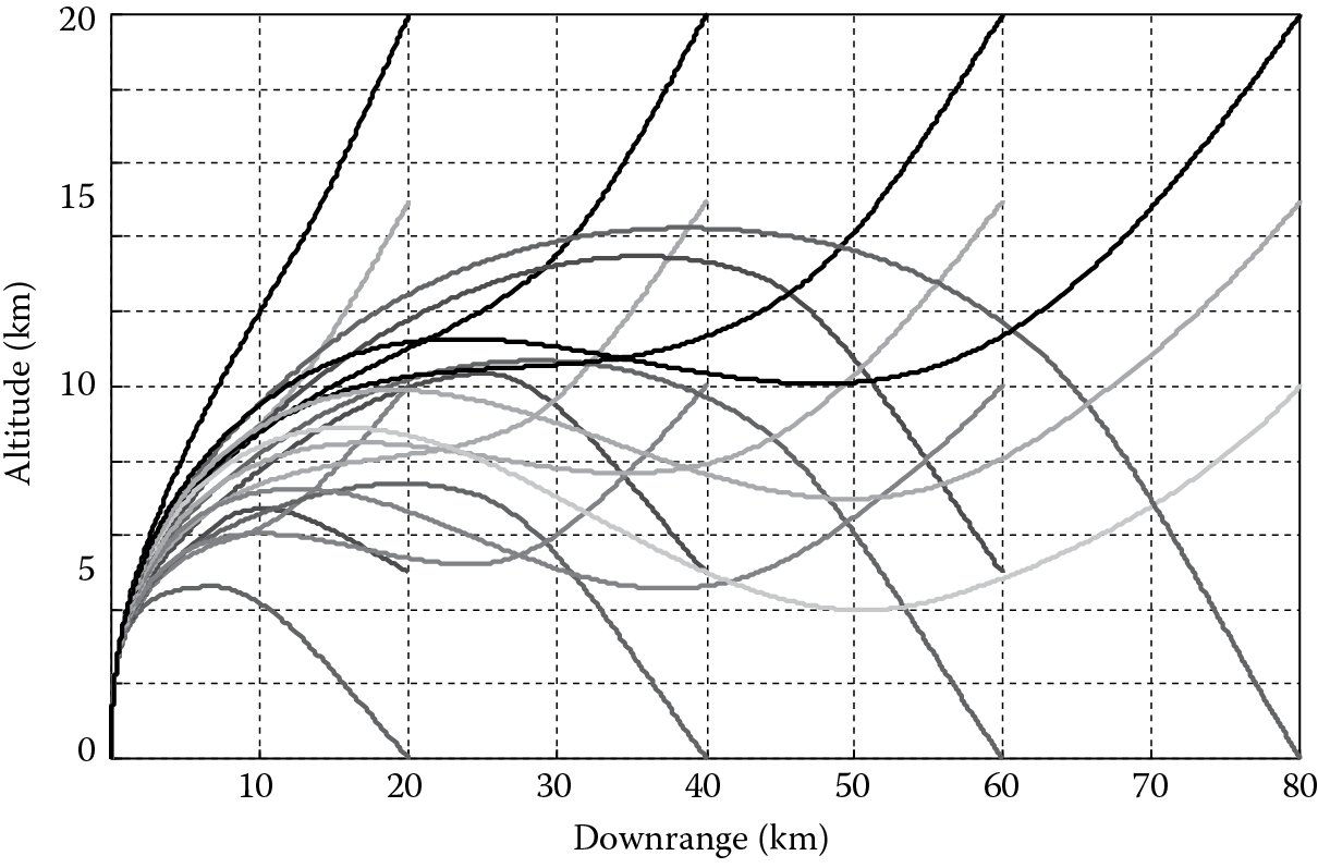
The strategies employed in the examples shown in Figure 5.13 are simple compared to the range of possibilities that can be explored to satisfy requirements. This strategy shows that in engagements below 10,000 m altitude, a direct 75° angle approach to the target is chosen that may be appropriate for a cruise missile defense strategy. Engagements at 10,000 m altitude and above employ an inverse trajectory approach to the target of 45° that may be appropriate for a terminal ballistic missile defense strategy. Figure 5.14 shows the time-of-flight variations associated with the trajectory-shaping variations.

From the results shown in Figure 5.13 and Figure 5.14, flyout tables can be constructed and used when developing engagement subsystem flow down requirements.
5.5 CDS: Sensor Suite System Performance Requirements
The following discussion will focus on developing radar requirements for detecting targets at a given range and developing and understanding the sensor suite system–level performance trade-offs for achieving a given detection range. Figure 5.15 shows the process for allocating missile defense system requirements to the radar system given a keep-out volume requirement for engaging targets in operational environments.

The key radar design parameters are detection range, range accuracy, angle accuracy, and the time it takes for searching out the surveillance volume. The allocation begins with CDS specifications and combined with sensor suite doctrine specifications, ISR specifications, target and environment specifications, and platform specifications. The keep-out volume is specified from the functional requirements when these components are combined.
The detection range, which is related to the firm track range, must support the keep-out volume requirement. The radar detection range can be readily determined from the radar range equation, which is a function of key radar performance parameters. Key radar performance parameters can be selected in order to achieve a detection range that supports the keep-out volume when combined with CDS time constant and the engagement system boundaries (to be discussed in Section 5.4). Moreover, the range and angle accuracy must support missile seeker handover requirements. The radar needs to guide the missile to a point in space such that when the missile goes into terminal guidance mode, the target is contained in the missile seeker field of view.
The radar architecture can be based on a rotating antenna or phased array. A rotating antenna radar is typically a 2D radar with a wide elevation beam that determines target range and azimuth. A phased array radar is a 3D radar that incorporates an electronically scanned beam to determine the target location in range, azimuth, and elevation. A tracking filter processes successive target position updates to improve the accuracy of the location estimates and estimates the target velocity and acceleration components. A rotating phased array radar scans the pencil beam in azimuth mechanically while the beam is electronically scanned in elevation.
A phased array radar antenna can be passive or active. Passive phased arrays have a separate transmitter that usually incorporates microwave tubes such as traveling wave tubes (TWTs) or crossed-field amplifiers (CFAs). An example is the SPY-1 Radar, which has a multistage transmitter that incorporates both TWTs and CFAs. Active phased arrays incorporate transmit/receive (T/R) modules that are integral to the antenna and located behind each antenna element.
A notional architecture for the passive phased array of three elements is shown in Figure 5.16. This architecture is scalable to phased arrays with thousands of radiating elements. A waveform generator (WFG) generates and provides a low-power radar pulse to the centralized transmitter that is typically a microwave tube–based transmitter. The transmitter amplifies the radar pulse to high power. Next, the high-power radar signal is divided and distributed to the individual radiating elements by the transmit beamformer. The transmit beamformer typically provides equal power to each element by using a waveguide power splitting network. The circulator at each element provides isolation between transmit and receive paths to help protect the receiver during high-power pulse transmission. Next, the radar pulse passes through a phase shifter. The phase shifters are used to apply a linear phase gradient across the array face, steering the beam in a desired direction for the transmit frequency. Phase shifters are typically narrowband and need to be reset if the radar frequency is changed significantly to keep the antenna beam steered in the same direction. The phase shifters are also reset to steer the beam to a new beam position.

On receive, the phase shifter settings are maintained to keep the receive beam aligned with the transmit beam. The receive signal is directed by the circulator to the receive beamforming network, which is a low-power microwave network. The receive beamformer typically applies a low sidelobe weighting where the element locations moving toward the edge of the array are more strongly weighted than those in the center of the array. The receive beamformer for a passive low sidelobe phased array typically has high losses due to the implementation of the low sidelobe weighting. This large loss ahead of the low-noise amplifier (LNA) limits the radar noise figure and sensitivity. The LNA output is first downconverted to an intermediate frequency or baseband and then converted to digital signal by the A-to-D converter for subsequent digital signal processing.
The architecture for a notional three-element active phased array is shown in Figure 5.17. The transmit and receive functions are distributed and contained in transmit/receive (T/R) modules that are located in close proximity to the radiating elements. The WFG output is now divided and distributed to each T/R module. Both transmit and receive losses are significantly reduced compared to the passive phased array architecture. The receive weighting for low sidelobes now occurs after the LNA supporting a lower system noise figure and increased radar sensitivity. Because of these architectural differences, an active phased array typically supports a 10 dB improvement in radar sensitivity compared to a passive array.

Ultimately, radar performance will be limited by prime power, cooling, and weight constraints associated with the platform (e.g., shipborne, airborne, or mobile land-borne). The radar efficiency, which is defined as the ratio of radiated power to required prime power, affects both prime power and cooling requirements. Weight must be minimized for airborne and mobile land-borne radar systems. Weight is less of an issue for shipborne radar systems; however, the weight will impact how the radar antenna can be mounted on a ship. It is desirable for a shipborne antenna to be mounted as high as possible to maximize the radar horizon for low-flying targets.
The radar range equation for a clear environment from Blake [26] is
Rmax = [(PtGtGrσλ2Ft2Fr2)/(4π)3(S/N)minkTsBnL]1/4 (5.26)
The maximum range is a statistical quantity that is coupled to the minimum required signal-to-noise (S/N) ratio. Typically, a detection range probability of 90% is used. To maximize the radar detection range, it is desired to maximize terms in the numerator while minimizing terms in the denominator. The target radar cross section, σ, is based on the required targets to be engaged.
One of the first steps is to select a radar frequency band. The target radar cross section (RCS) is a function of aspect angle, frequency, and polarization. Therefore, the target RCS is somewhat variable and statistical in nature. The pattern propagation factor is a transmit loss (Ft2) and a receive loss (Fr2) that results from multipath interference. These two quantities are generally less than unity although under certain conditions, multipath can be constructive. The level of interference depends on the terrain, propagation conditions, radar frequency, radar height, and target altitude. The pattern propagation factor is generally worse at lower radar frequencies, lower radar heights, and lower target altitudes under standard propagation conditions. For shipborne applications, X-band radars are generally preferred for the detection of low-altitude targets. X-band extends from 8 to 12 GHz. X-band radars are also generally smaller and lighter than S-band radars, so they can be placed higher on the ship’s structure. S-band extends from 2 to 4 GHz. Pattern propagation factors for typical S- and X-band antenna heights for shipborne installations are illustrated in Figure 5.18 as a function of target height and range [27].

Pattern propagation factor comparison of an S-band (antenna height 14 m) and X-band (antenna height 26 m) in dB under standard propagation conditions. (From Hough, M.E., AIAA Journal of Guidance, Control, and Dynamics , 18(5), 959, September–October 1995 [22].)
Once a frequency band is selected, the antenna size (or gain) and transmitter power can be traded to achieve the required detection range to support the keep-out volume requirement. The radar detection range required to support the keep-out volume requirement is also dependent on the minimum target RCS, maximum inbound target velocity, and missile speed. For example, a notional S-band (~3 GHz) requirement is used to detect a −20 dBsm target at a range of 50 km in the presence of a 20 dB two-way pattern propagation factor loss. The radar pulse width, τ, is 50 μs and the losses, L, are 6 dB. In addition, the minimum required signal-to-noise ratio is 13 dB and the system noise temperature, Ts, is 30 dB, which is a typical value for passive phased array radars. The fixed parameters for a notional passive phased array radar are summarized in Table 5.2. This requires the combination of transmit power, transmit gain, and receive gain (PtGtGr) to be 144.4 dB.
Fixed Radar Design Parameters
|
Radar Parameter |
Value (dB) |
|
|
σ —minimum target radar cross section (m2 ) |
−20 |
|
|
λ 2 —radar wavelength (m2 ) |
−20 |
|
|
F t 2 F r 2 —minimum two-way pattern propagation factor |
−20 |
|
|
(4π)3 —constant |
33 |
|
|
(S/N )min —90% probability of detection and false alarm rate 10−6 against nonfluctuating target |
13 |
|
|
k —Boltzmann’s constant (W s/degree) |
−228.6 |
|
|
T s —system noise temperature at antenna terminals (K) |
30 |
|
|
B n —noise bandwidth or 1/τ (Hz or 1/s) |
43 |
|
|
L —losses |
6 |
|
|
Total (dBm4 ) |
43.6 |
|
|
Required total (dBm4 ) |
188 |
|
|
Required P t G t G r (dB) |
144.4 |
|
|
Radar Design Parameter |
Passive Array |
Active Array |
|
Transmitter peak power, P t |
1 MW |
0.2 MW |
|
Transmit antenna gain, G t |
43.2 dB |
41.7 |
|
Receive antenna gain, G r |
41.2 dB |
39.7 |
|
Antenna area, A |
16.6 m2 |
11.8 m2 |
|
Antenna diameter, D |
4.6 m |
3.9 m |
|
Number of elements, N |
5750 |
4100 |
|
Peak power per element |
175 W |
49 W |
Allocating this requirement equally among the transmit power and transmit and receive gain results in a transmitter peak power requirement of 65 kW and an antenna size of 51.8 m2 or a diameter of 8.1 m. Clearly, an antenna diameter of 8.1 m is not practical. However, a transmitter with a peak power level of 1 MW is practical using crossed-field amplifier (CFA) microwave tube technology. This results in an antenna size of 13.2 m2 or a diameter of 4.1 m, which may be possible for a shipborne system. A 13.2 m2 antenna would contain approximately 4600 elements in a triangular lattice. The use of a triangular lattice versus a rectangular lattice reduces the number of elements required by approximately 13% [29]. The required peak power per element is 217 W.
Several other techniques can be used to increase radar sensitivity. The pulse width, τ, can be increased or multiple pulses can be integrated. Both approaches have radar performance trade-offs. For example, pulse widths as large as a millisecond are possible, but the longer the pulse width, the longer the radar minimum range. The radar receiver cannot be turned on until after the pulse is transmitted to isolate the radar receiver during transmit. The minimum radar range is
Rmin = cτ/2 (5.27)
where c is the speed of light (3 * 108 m/s). For a 1 ms pulse width, the minimum radar range is 150 km.
Long pulse widths can be useful for searching long-range targets. The 50 μs pulse width used in the aforementioned example has a 7.5 km minimum range. An energy management design feature to account for this could be to reduce the pulse width as the targets approach the radar.
Integrating multiple radar pulses typically requires more radar time. In an unambiguous range waveform, the next pulse is transmitted after the time required for a target return from the maximum range of interest. This approach can potentially increase radar search frame times and may be more appropriate for holding a target in track once it is detected. Range ambiguous waveforms transmit successive pulses before the target returns arrive from the maximum range of interest. Multiple radar dwells at different pulse repetition frequencies (PRFs) are required to resolve the range ambiguity. In addition, blind ranges result over the target range interval of interest for a single PRF. So, multiple PRF dwells are also needed to unblind the range interval of interest. Both of these approaches can potentially increase radar search frame times and may be more appropriate for holding a target in track once it is detected to minimize radar timeline impact.
5.5.1 Radar Architecture
Radar architecture can also be exploited to achieve radar detection range requirements. An alternative radar design would be to use an active phased array approach that provides a sensitivity improvement over a passive array of approximately 10 dB. This reduces the required PtGtGr to 134.4 dB. Again allocating the requirement equally among the transmit power and transmit and receive gain results in a transmitter peak power requirement of 30.2 kW and an antenna size of 24 m2 or a diameter of 5.5 m containing approximately 8350 elements. A T/R module at S-band can provide 50–100 W of peak power. A 0.2 MW total peak power requirement is feasible. This results in an antenna size of 9.3 m2 or a diameter of 3.5 m containing approximately 3250 elements. The total transmit power can be achieved with approximately 55 W of peak power per element.
The sizing of radar antennas discussed earlier assumes that both transmit and receive aperture illuminations are uniform across the array elements. A uniform aperture weighting function provides the highest gain; however, the sidelobes are also somewhat high. A uniform circular illumination results in a first sidelobe level of approximately −17 dB. In practice, a low sidelobe weighting is used for the receive pattern to mitigate interference in the sidelobes from jamming and clutter. A weighting for receive sidelobes of −50 dB results in a taper loss, η, of approximately 2 dB. This taper loss reduces the receive gain by 2 dB. To compensate for the taper loss, the radar design must be adjusted to incorporate higher transmitter peak power, larger antenna area, or a combination of both.
Increasing the antenna area by 1 dB or 26% will compensate for the 2 dB taper loss. The resultant PtGtGr, antenna area and diameter, number of array elements, and peak power per element summarized in Table 5.3 for notional passive and active S-band phased array designs will satisfy the detection range requirement. In the context of the system design, the detection range requirement would support missile engagements that support the keep-out volume requirement against the required targets. Table 5.3 provides a summary of S-band phased array design options.
Summary of S-Band Passive and Active Radar Phased Array Designs
|
Passive Array |
Active Array |
|
|
Peak transmit power |
1 MW |
0.2 MW |
|
Transmit loss |
3 dB |
1 dB |
|
Duty factor |
0.02 |
0.10 |
|
Efficiency |
0.10 |
0.20 |
|
Average radiated power |
10 kW |
15.9 kW |
|
Prime power required |
100 kW |
79.4 kW |
|
Dissipated power |
90 kW |
63.5 kW |
The active array design results in a somewhat smaller aperture and has lower transmitter power requirements, potentially allowing it to be placed higher on a shipborne platform. The increased height would provide some radar horizon extension, potentially increasing the detection range against low-flying targets.
Phased array radars, unlike older passive rotating radars, provide horizon to zenith coverage by electronically scanning the beam throughout the coverage volume. In order to provide full hemispherical coverage, phased array radars usually consist of three or four identical array faces that are equally spaced in azimuth. In active phased arrays, the transmitter and receiver functions are also contained in the arrays. In advanced active phased arrays, some of the signal-processing functions are also in the antenna. These factors tend to make the cost of the phased array system much more expensive than a rotating radar system. In some cases, rotating phased arrays are used that scan the beam electronically in elevation while covering azimuth with the mechanical rotation.
The multiface phased array radars can typically scan the coverage volume at higher rates and have the capability to electronically tailor the scans so that target sectors have higher revisit rates. Typically, the coverage volume is divided into a short-range horizon sector and a long-range above horizon sector. The horizon sector has much shorter revisit times usually on the order of several seconds. In addition, if the radar track loading in the horizon sector becomes high, the revisit rate in the above horizon sector can be slowed to maintain the horizon search frame time or to minimize the increase in horizon search frame time.
5.5.2 Platform Constraints
The platform needs to provide prime power and cooling for the radar system. In addition, the weight of the radar antenna will limit how high it can be placed in a shipborne application. The prime power requirement must account for the efficiency of a radar system. The efficiency is defined as the ratio of power radiated to prime power required. A passive phased array radar typically has an efficiency of 10%, while active phased array radar can have an efficiency of up to 20%. The radiated power is the average transmit power reduced by the transmit losses. The average transmit power is the peak transmit power times the duty factor. Typical duty factors for passive and active phased array radars are 2% and 20%, respectively. Transmit losses are typically about 3 dB for a passive phased array and 1 dB for an active phased array. The prime power requirements for the passive and active array designs are derived using the data summarized in Table 5.4.
Radar Power Requirement Summary
|
Passive Array |
Active Array |
|
|
Peak transmit power |
1 MW |
0.2 MW |
|
Transmit loss |
3 dB |
1 dB |
|
Duty factor |
0.02 |
0.10 |
|
Efficiency |
0.10 |
0.20 |
|
Average radiated power |
10 kW |
15.9 kW |
|
Prime power required |
100 kW |
79.4 kW |
|
Dissipated power |
90 kW |
63.5 kW |
The passive phased array radar requires 100 kW of prime power compared to 79.4 kW of prime power for the active phased array radar, which means that the active phased array radar required approximately 21% less power. The dissipated power is directly correlated with cooling requirements. The active array radar requires approximately 30% less cooling capacity to remove the dissipated power heat load.
The weight of an active phased array antenna will typically be greater than a passive phased array antenna for a fixed antenna diameter. The active array antenna will be heavier due to the distributed receiver and transmitter components that are integrated into the array face. For the passive and active array radar designs, the antenna diameters are 4.1 and 3.5 m, respectively. Since arrays are not the same diameter, a detailed weight analysis would be required to determine actual antenna weights. One way to potentially reduce the antenna size and weight is to change the radar frequency from S-band to X-band. A given aperture size will produce about 5 dB more antenna gain at X-band versus S-band. Therefore, the two-way gain is increased by about 10 dB. This allows smaller and lighter-weight antennas to be considered; however, changing the frequency band has other performance considerations that were discussed in the requirements section.
5.6 Engagement System Performance Requirements
The engagement system (ES) is required to destroy the target system (TS). The engagement system operates when supported by the central defense system (CDS) as specified by the system performance specifications. From this point forward, the engagement system will be limited to air defense missile systems.
The first air defense interceptor (ADI) performance requirement to address is the engagement boundaries necessary to defend the keep-out zone of the defended asset. This is necessary before the engagement system requirement development process can be put into place. A notional range–altitude engagement boundary can be derived as shown in Figure 5.19. Depending on the target characteristics, the engagement boundaries for a given ADI will change. High-speed targets will, for example, collapse the engagement boundaries more quickly than low-speed targets due to the fact that the success of the engagement is dependent on not breeching some minimum dynamic pressure to sustain maneuverability and time-constant performance and having a minimum homing time. Therefore, any set of engagement boundaries must assume that target acquisition occurs at some minimum kinematic boundary of the missile system that statistically ensures an acceptable Pssk. Range–altitude boundaries will decrease in areas when the targets are in an ECM environment, in a high sea state (when over water), against a maneuvering target or when a number of other anomalous conditions exist. Therefore, the engagement boundary requirement is specified with a number of qualifiers including specific performance conditions. In the capability-based acquisition process, a required engagement boundary is developed but it may need to be purchased over many iterations/years in a spiral fashion. It is important to first deploy some measurable capability with a system and plan for growth in achievable steps that will satisfy both fiscal and schedule realities.

Figure 5.19, range–altitude engagement requirements, displays performance-limiting factors. These factors need to be considered in the engagement system requirement flow down process. Initial engagement boundary design criteria include minimum acceptable Pssk, which incorporates interceptor miss distance criteria and target signature, velocity profile, and vulnerability characteristics. The requirement shown in Figure 5.19 can be interpreted as that performance when launched on a standard atmospheric day while engaging a nonmaneuvering benign target described by the associated features (σ, V, υ). The missile is required to be capable of intercepting targets with a minimum Pssk ≥ p at an altitude greater than or equal to Hmin meters and an altitude of less than or equal to Hmax kilometers and within a range boundary of no less than Rmin kilometers and out to a maximum range Rmax kilometers. The minimum and maximum range–altitude boundary will exist due to minimum dynamic pressure and thus maneuverability and kinematic limits. Achieving acceptable outer and inner range–altitude boundaries will be the focus of design driven primarily by target kinematic and dynamic capabilities. Figure 5.19 also shows the maximum boundary where the CDS will be required to handover guidance and control to the engagement system. If handover is delayed to this point in the envelope, then an active or passive sensor system or suite will need to be employed by the engagement system. Were handover to occur prior to this limit, then a semi-active radar sensor system would fulfill requirements and may be preferable. Essentially, this limit is the horizon or the electronic horizon that will vary due to anomalous propagation conditions and frequencies employed.
The next boundary that will need to be defined is the Mach–altitude envelope. The trade space of the AMD system will ultimately measure achieving acceptable Pssk beyond the keep-out zone, which in turn is a time requirement. The time requirement will be satisfied by balancing the sensor suite detection capability against the engagement system flyout time contour. Cueing from ISR components and speeding up CDS reaction time will play a role in the trade space but will be shown to have second-order effects in comparison to achieving increased detection range and speed at which ordnance can be delivered. ISR cueing and reaction time reduction will be fine-tuning, whereas the sensor suite detection range capability and the engagement system speed will be critical design parameters.
A notional Mach–altitude engagement envelope is shown in Figure 5.20 that displays performance-limiting factors that need to be considered in the aerodynamic–propulsive design requirement flow down process. The engagement boundary Figure 5.19 and Figure 5.20 and the itemized requirements are linked by altitude and Pssk through miss distance requirements. Miss distance is tightly coupled to missile time constant that is in turn tightly coupled to dynamic pressure (Q), or velocity. There are four requirements specified in Figure 5.20 that need to be achieved. M-LL represents the two Mach–low-altitude limit requirements and M-UL represents the two Mach–upper-altitude limit requirements. The requirement driver achieves a minimum miss distance probability, Pm ≥ p′. Beyond this requirement set, the limiting factors are airframe/radome thermal, structural, and lift-to-weight ratio limits. The Mach–altitude envelope requirement will need to be expanded to deal with a more energetic target set. The primary factors to consider are target speed and maneuverability limits. As these two target characteristics increase, the Mach–altitude boundary requirements will need to grow. A boost propulsion system is required to achieve a minimal Mach limit where a sustain propulsion system can take over. The sustainer can be either a solid rocket motor or an air-breathing propulsion system. An air-breathing system will involve additional or more stringent limiting factors that need to be considered to meet the Mach–altitude requirement including angle of attack, propulsion chattering, and inlet operating limits.

Engagement Mach–altitude envelope. (Modified from Menon, P.K.A. and Briggs, M.M., AIAA Journal of Guidance, Control, and Dynamics , 13(4), 596, July–August 1990 [24].)
One last note on engagement boundaries is necessary. The engagement boundaries need to represent the acceptable degradation in performance due to conditions to be specified in the remaining part of this process.
Once the engagement system requirement envelopes are developed and the blanks that need to be determined are defined, it is then possible to begin assembling the specification tree that will completely identify the system performance and interface requirements. Specifications are the documentation of requirements that will include identifying what the system is being designed to accomplish (the system function). An important element of the function specifications is to document the purpose for the system. This is accomplished through the engagement boundaries, Figure 5.19 and Figure 5.20, derived from a flow down of the functional requirements.
Next, the components make up the system and how those components interrelate (interface requirements) is established. This is also sometimes referred to as the budgeting and allocation process. The system budget will include a breakout of the required operations of the system and an allocation to subsystems, components, or elements. Specific rules on how to use the system in conjunction with operations and components to meet the system requirements are all essential parts of the budgeting process. Finally, this process will include identifying how the system and its components will perform (performance requirements), which includes defining how the performance is to be verified (inspection, test, or demonstration). A performance margin must be established to ensure that both design and system meet the requirements.
Figure 5.21 shows the flow for engagement system specification development. This begins with the functional requirement flow down into the formation of engagement envelopes discussed earlier. The complete set of CDS interface specifications must flow down. CDS interface specifications have also evolved from and are evolving from the specification development process within the CDS that includes sensor suite, battle management, and engagement computer systems. In other words, the development of system-level requirements and subsequently the specifications will be part of the trade space that needs to flex with the preliminary design development in order to achieve mission goals and within the other constraints.

The process requires a first pass to define five specifications before proceeding further. The policy/rules of engagement/doctrine is an additional set of constraints to be placed on the development of engagement solutions. This includes prohibited cost boundaries, prohibited solution sets (at one time, e.g., there were prohibitions from developing space-based interceptors), minimum acceptable cumulative probability-of-kill solutions, prohibited or preferred kill mechanisms (this could include nuclear or other types of politically sensitive approaches), and launching conditions to include sea, land, space, air environments, and specific launching systems. The extremes of launching conditions will be specified as well to include weather conditions (i.e., temperature, wind precipitation extremes).
The target and environment specification will be developed to include whether engagement specifications are in a clear environment, electronic attack environment, multiple target environments, or possibly a number of other conditions.
The constraints combined with the target set will in turn drive/limit the remaining three first pass specifications: lethality mechanism, seeker, and terminal approach specifications. This loop may take several iterations to develop a comprehensive set of requirements and specifications that can then flow down to the remaining pieces of the process.
Lethality mechanism, seeker, and terminal approach strategy are closely coupled specifications. A hit-to-kill lethality strategy, for example, will put small wavelength constraints on the seeker system specification to permit the accuracy that will be required to ensure the required Pssk. Moreover, the targets’ characteristics will drive which wavelength strategies may be preferred. The terminal homing approach may be dictated as the combination of constraints accumulates. Midcourse guidance performance provided by CDS will drive seeker requirements and design decisions.
5.7 System Requirements Document
Once the specifications are settled for the first complete pass through the process and the Pssk performance requirement has been settled relative to the required engagement boundaries, which may be a variable mapping throughout the boundaries, it is necessary to document the conclusions in the system requirements document.
The SRD completes Phase A of the systems engineering process with a review by the entire acquisition team. The document should contain the completed work including the mission needs statement, TLR/MOEs, CONOPS, top-level architecture (TLA), and system specifications. Within the TLA, there will be an air and missile defense system, target system, and ISR system. Within the air and missile defense system, there will be the central defense system and the engagement system. Within the CDS, there will be a sensor suite system, battle management system, and engagement computer system. System specifications are developed and flow through the architecture beginning with the establishment of a technical and policy-based keep-out volume with respect to defended assets.
The ISR system specifications include producing the target origin, conducting geopositioning, and communicating to the AMD system. The AMD system specifications include producing the required engagement boundaries, detect and track, doctrine, engagement solutions, and communication throughout the AMD system. Assembling detailed target characterizations with respect to sensor suite system and engagement system solutions as specifications are also required.
Moreover, it is proposed that within the engagement system the constraints that apply to AMD engagement be imposed. Although there will be subordinated constraints associated specifically with their operation within the other systems, it is within the engagement system operation that the constraints will flow more effectively and efficiently. Engagement system requirements include flyout Mach–altitude and range–altitude boundaries, midcourse guidance, terminal homing, and lethality strategies. The engagement system communication requirements are specified within the air and missile defense system.
References
1. Foard, T.R., Theater air defense cornerstones, Johns Hopkins APL Technical Digest, 21(3), 387–392, 2000.
2. Yopp, S.W., Aegis and the C/JFACC: The Naval Surface Combatant as an Element of Air and Space Power, AU/ACSC/2395/AY06, Air Command and Staff College Air University, Montgomery, AL, April 2006.
3. Hartwig, G., Aegis, from MIL-SPEC to open systems, in NDIA Systems Engineering Conference, Tampa, FL, October 21–24, 2002.
4. O’Rourke, R., Sea-Based Ballistic Missile Defense—Background and Issues for Congress, RL33745, CRS Report for Congress, Washington, DC, November 21, 2008.
5. Lawes, I.S., Defence against terrorism—A role for ground based air defence, in Land Warfare Conference 2007, Adelaide, South Australia, Australia, October 2007.
6. Lussier, F. et al., Army Air and Missile Defense-Future Challenges, RAND Corporation, Santa Monica, CA, 2002.
7. GAO-04-175, Nonproliferation—Improvements Needed to Better Control Technology Exports for Cruise Missiles and Unmanned Aerial Vehicles, Washington, DC, January 2004.
8. Weidler, R.D., Target LOS and seeker head equations for an AAM simulation, Flight Dynamics Group, Stability and Flight Control Section, FZE-977, November 19, 1969.
9. Bose, S.C., Radar updated strapdown inertial midcourse guidance performance analysis for missiles, AIAA Paper 79-1726, Reston, VA, 1979.
10. Kouba, J.T. and Bose, S.C., Terminal seeker pointing-angle error at target acquisition, IEEE Transactions on Aerospace and Electronic Systems, AES-16(3), 313–319, May 1980.
11. Stallard, D.V., Classical and modern guidance of homing interceptors, Seminar of Department of Aeronautics and Astronautics, Massachusetts Institute of Technology, Cambridge, MA, April 1968.
12. Lin, C.F., Modern Navigation, Guidance and Control Processing, Prentice Hall, Englewood Cliffs, NJ, 1991.
13. Serakos, D. and Lin, C.-F., Linearized kappa guidance, Journal of Guidance, Control, and Dynamics, 18(5), 975–980, 1995.
14. Lee, G.K.F., Estimation of the time-to-go parameter for air-to-air missiles, AIAA Journal of Guidance, Control, and Dynamics, 8(2), 262–266, 1984.
15. Massoumnia, M., Optimal midcourse guidance law for fixed propulsive maneuvers, AIAA Journal of Guidance, Control, and Dynamics, 18(3), 465–470, May–June 1995.
16. Hablani, H., Pulsed guidance of exo-atmospheric interceptors with image processing delays in angle measurements, in AIAA Guidance, Navigation and Control Conference and Exhibit, Denver, CO, August 14–17, 2000.
17. Ben Asher, J.Z. and Yaesh, I., Optimal guidance with a single uncertain time lag, AIAA Journal of Guidance, Control, and Dynamics, 18(5), 981–988, September–October 1995.
18. Kumar, R.R., Seywald, H., and Cliff, E.M., Near-optimal three-dimensional air-to-air missile guidance against maneuvering target, AIAA Journal of Guidance, Control, and Dynamics, 18(3), 457–464, May–June 1995.
19. Kumar, R.R., Seywald, H., Cliff, E.M., and Kelley, H.J., Three-dimensional air-to-air missile trajectory shaping, AIAA Journal of Guidance, Control, and Dynamics, 18(3), 449–456, May–June 1995.
20. Bezick, S., Rusnak, I., and Gray, W.S., Guidance of a homing missile via nonlinear geometric control methods, AIAA Journal of Guidance, Control, and Dynamics, 18(3), 441–448, May–June 1995.
21. Yang, S.-M., Analysis of optimal midcourse guidance law, IEEE Transaction on Aerospace and Electronic Systems, 32(1), 419–425, January 1996.
22. Hough, M.E., Optimal guidance and nonlinear estimation for interception of accelerating targets, AIAA Journal of Guidance, Control, and Dynamics, 18(5), 959–968, September–October 1995.
23. Imado, F., Kuroda, T., and Miwa, S., Optimal midcourse guidance for medium-range air-to-air missiles, AIAA Journal of Guidance, Control, and Dynamics, 13(4), 603–608, July–August 1990.
24. Menon, P.K.A. and Briggs, M.M., Near-optimal midcourse guidance for air-to-air missiles, AIAA Journal of Guidance, Control, and Dynamics, 13(4), 596–602, July–August 1990.
25. Yanushevsky, R., Modern Missile Guidance, CRC Press, Boca Raton, FL, 2008.
26. Blake, L., Radar Range-Performance Analysis, Munro Publishing Company, Silver Spring, MD, 1991, p. 17.
27. Courtesy of Huong Pham of Technology Service Corporation, Silver Spring, MD.
28. AIAA/ANSI, R-004-1992, Recommended Practice for Atmospheric and Space Flight Vehicle Coordinate Systems. AIAA, 370 L’Enfant Promenade, SW, Washington DC 20024, 28 February 1992.
29. Sharp, E., A triangular array of planar-array elements that reduces the number needed, IRE Transactions on Antennas and Propagation, 9, 126–129, March 1961.