
ARM AND THUMB ASSEMBLER INSTRUCTIONS
A.3. ALPHABETICAL LIST OF ARM AND THUMB INSTRUCTIONS
This appendix lists the ARM and Thumb instructions available up to, and including, ARM architecture ARMv6, which was just released at the time of writing. We list the operations in alphabetical order for easy reference. Sections A.4 and A.5 give quick reference guides to the ARM and GNU assemblers armasm and gas.
We have designed this appendix for practical programming use, both for writing assembly code and for interpreting disassembly output. It is not intended as a definitive architectural ARM reference. In particular, we do not list the exhaustive details of each instruction bitmap encoding and behavior. For this level of detail, see the ARM Architecture Reference Manual, edited by David Seal, published by Addison Wesley. We do give a summary of ARM and Thumb instruction set encodings in Appendix B.
A.1 USING THIS APPENDIX
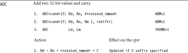
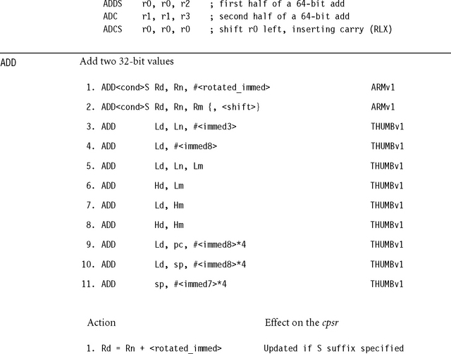
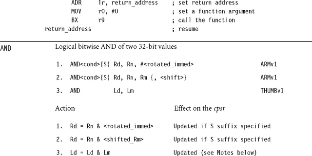
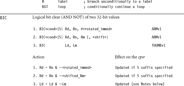
Each appendix entry begins by enumerating the available instructions formats for the given instruction class. For example, the first entry for the instruction class ADD reads
![]()
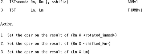
The fields <cond> and <rotated_immed> are two of a number of standard fields described in Section A.2. Rd and Rn denote ARM registers. The instruction is only executed if the condition <cond> is passed. Each entry also describes the action of the instruction if it is executed.
The {S} denotes that you may apply an optional S suffix to the instruction. Finally, the right-hand column specifies that the instruction is available from the listed ARM architecture version onwards. Table A.1 shows the entries possible for this column.
Table A.1
| Type | Meaning |
| ARMvX | 32-bit ARM instruction first appearing in ARM architecture version X |
| THUMBvX | 16-bit Thumb instruction first appearing in Thumb architecture version X |
| MACRO | Assembler pseudoinstruction |
Note that there is no direct correlation between the Thumb architecture number and the ARM architecture number. The THUMBv1 architecture is used in ARMv4T processors; the THUMBv2 architecture, in ARMv5T processors; and the THUMBv3 architecture, in ARMv6 processors.
Each instruction definition is followed by a notes section describing restrictions on the use of the instruction. When we make a statement such as “Rd must not be pc,” we mean that the description of the function only applies when this condition holds. If you break the condition, then the instruction maybe unpredictable or have predictable effects that we haven’t had space to describe here. Well-written programs should not need to break these conditions.
A.2 SYNTAX
We use the following syntax and abbreviations throughout this appendix.
A.2.1 OPTIONAL EXPRESSIONS
![]() {<expr>} is an optional expression. For example, LDR{B} is shorthand for LDR or LDRB.
{<expr>} is an optional expression. For example, LDR{B} is shorthand for LDR or LDRB.
![]() {<exp1>|<exp2>|…|<expN>}, including at least one “|” divider, is a list of expressions. One of the listed expressions must appear. For example LDR{B|H} is shorthand for LDRB or LDRH. It does not include LDR. We would represent these three possibilities by LDR{|B|H}.
{<exp1>|<exp2>|…|<expN>}, including at least one “|” divider, is a list of expressions. One of the listed expressions must appear. For example LDR{B|H} is shorthand for LDRB or LDRH. It does not include LDR. We would represent these three possibilities by LDR{|B|H}.
A.2.2 REGISTER NAMES
![]() Rd, Rn, Rm, Rs, RdHi, RdLo represent ARM registers in the range r0 to r15.
Rd, Rn, Rm, Rs, RdHi, RdLo represent ARM registers in the range r0 to r15.
![]() Ld, Ln, Lm, Ls represent low-numbered ARM registers in the range r0 to r7.
Ld, Ln, Lm, Ls represent low-numbered ARM registers in the range r0 to r7.
![]() Hd, Hn, Hm, Hs represent high-numbered ARM registers in the range r8 to r15.
Hd, Hn, Hm, Hs represent high-numbered ARM registers in the range r8 to r15.
![]() Cd, Cn, Cm represent coprocessor registers in the range c0 to c15.
Cd, Cn, Cm represent coprocessor registers in the range c0 to c15.
![]() sp, lr, pc are names for r13, r14, r15, respectively.
sp, lr, pc are names for r13, r14, r15, respectively.
![]() Rn[a] denotes bit a of register Rn. Therefore Rn[a] = (Rn
Rn[a] denotes bit a of register Rn. Therefore Rn[a] = (Rn ![]() a) & 1.
a) & 1.
![]() Rn[a:b] denotes the a + 1 – b bit value stored in bits a to b of Rn inclusive.
Rn[a:b] denotes the a + 1 – b bit value stored in bits a to b of Rn inclusive.
![]() RdHi:RdLo represents the 64-bit value with high 32 RDHi bits and low 32 bits RdLo.
RdHi:RdLo represents the 64-bit value with high 32 RDHi bits and low 32 bits RdLo.
A.2.3 VALUES STORED AS IMMEDIATES
![]() <immedN> is any unsigned N-bit immediate. For example, <immed8> represents any integer in the range 0 to 255. <immed5>*4 represents any integer in the list 0, 4, 8, …, 124.
<immedN> is any unsigned N-bit immediate. For example, <immed8> represents any integer in the range 0 to 255. <immed5>*4 represents any integer in the list 0, 4, 8, …, 124.
![]() <addressN> is an address or label stored as a relative offset. The address must be in the range pc – 2N ≤ address < pc + 2N. Here, pc is the address of the instruction plus eight for ARM state, or the address of the instruction plus four for Thumb state. The address must be four-byte aligned if the destination is an ARM instruction or two-byte aligned if the destination is a Thumb instruction.
<addressN> is an address or label stored as a relative offset. The address must be in the range pc – 2N ≤ address < pc + 2N. Here, pc is the address of the instruction plus eight for ARM state, or the address of the instruction plus four for Thumb state. The address must be four-byte aligned if the destination is an ARM instruction or two-byte aligned if the destination is a Thumb instruction.
![]() <A-B> represents any integer in the range A to B inclusive.
<A-B> represents any integer in the range A to B inclusive.
![]() <rotated_immed> is any 32-bit immediate that can be represented as an eight-bit unsigned value rotated right (or left) by an even number of bit positions. In other words, <rotated_immed> = <immed8> ROR (2*<immed4>). For example 0×ff, 0×104, 0×e0000005, and 0×0bc00000 are possible values for <rotated_immed>. However, 0×101 and 0×102 are not. When you use a rotated immediate, <shifter_C> is set according to Table A.3 (discussed in Section A.2.5). A nonzero rotate may cause a change in the carry flag. For this reason, you can also specify the rotation explicitly, using the assembly syntax <immed8>, 2*<immed4>.
<rotated_immed> is any 32-bit immediate that can be represented as an eight-bit unsigned value rotated right (or left) by an even number of bit positions. In other words, <rotated_immed> = <immed8> ROR (2*<immed4>). For example 0×ff, 0×104, 0×e0000005, and 0×0bc00000 are possible values for <rotated_immed>. However, 0×101 and 0×102 are not. When you use a rotated immediate, <shifter_C> is set according to Table A.3 (discussed in Section A.2.5). A nonzero rotate may cause a change in the carry flag. For this reason, you can also specify the rotation explicitly, using the assembly syntax <immed8>, 2*<immed4>.
A.2.4 CONDITION CODES AND FLAGS
![]() <cond> represents any of the standard ARM condition codes. Table A.2 shows the possible values for <cond>.
<cond> represents any of the standard ARM condition codes. Table A.2 shows the possible values for <cond>.
Table A.2
| <cond> | Instruction is executed when | cpsr condition |
| {|AL} | ALways | TRUE |
| EQ | EQual (last result zero) | Z==1 |
| NE | Not Equal (last result nonzero) | Z==0 |
| {CS|HS} | Carry Set, unsigned Higher or Same (following a compare) | C==1 |
| {CC|LO} | Carry Clear, unsigned LOwer (following a comparison) | C==0 |
| MI | MInus (last result negative) | N==1 |
| PL | PLus (last result greater than or equal to zero) | N==0 |
| VS | V flag Set (signed overflow on last result) | V==1 |
| VC | V flag Clear (no signed overflow on last result) | V==0 |
| HI | unsigned HIgher (following a comparison) | C==1 && Z==0 |
| LS | unsigned Lower or Same (following a comparison) | C==0 ‖ Z==1 |
| GE | signed Greater than or Equal | N==V |
| LT | signed Less Than | N!=V |
| GT | signed Greater Than | N==V && Z==0 |
| LE | signed Less than or Equal | N!=V ‖ Z==1 |
| NV | NeVer—ARMv1 and ARMv2 only—DO NOT USE | FALSE |
![]() <SignedOverflow> is a flag indicating that the result of an arithmetic operation suffered from a signed overflow. For example, 0×7fffffff + 1 = 0×80000000 produces a signed overflow because the sum of two positive 32-bit signed integers is a negative 32- bit signed integer. The V flag in the cpsr typically records signed overflows.
<SignedOverflow> is a flag indicating that the result of an arithmetic operation suffered from a signed overflow. For example, 0×7fffffff + 1 = 0×80000000 produces a signed overflow because the sum of two positive 32-bit signed integers is a negative 32- bit signed integer. The V flag in the cpsr typically records signed overflows.
![]() <UnsignedOverflow> is a flag indicating that the result of an arithmetic operation suffered from an unsigned overflow. For example, 0×ffffffff + 1 = 0 produces an overflow in unsigned 32-bit arithmetic. The C flag in the cpsr typically records unsigned overflows.
<UnsignedOverflow> is a flag indicating that the result of an arithmetic operation suffered from an unsigned overflow. For example, 0×ffffffff + 1 = 0 produces an overflow in unsigned 32-bit arithmetic. The C flag in the cpsr typically records unsigned overflows.
![]() <NoUnsignedOverflow> is the same as 1 – <UnsignedOverflow>.
<NoUnsignedOverflow> is the same as 1 – <UnsignedOverflow>.
![]() <Zero> is a flag indicating that the result of an arithmetic or logical operation is zero. The Z flag in the cpsr typically records the zero condition.
<Zero> is a flag indicating that the result of an arithmetic or logical operation is zero. The Z flag in the cpsr typically records the zero condition.
![]() <Negative> is a flag indicating that the result of an arithmetic or logical operation is negative. In other words, <Negative> is bit 31 of the result. The N flag in the cpsr typically records this condition.
<Negative> is a flag indicating that the result of an arithmetic or logical operation is negative. In other words, <Negative> is bit 31 of the result. The N flag in the cpsr typically records this condition.
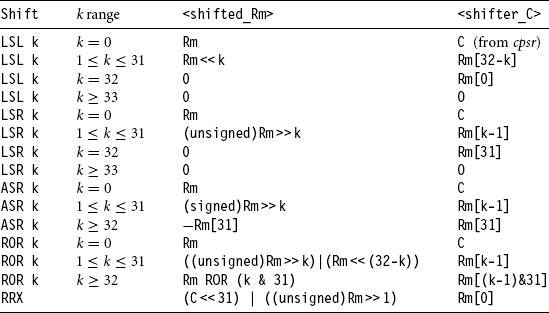
A.2.5 SHIFT OPERATIONS
![]() <imm_shift> represents a shift by an immediate specified amount. The possible shifts are LSL #<0-31>, LSR #<1-32>, ASR #<1-32>, ROR #<1-31>, and RRX. See Table A.3 for the actions of each shift.
<imm_shift> represents a shift by an immediate specified amount. The possible shifts are LSL #<0-31>, LSR #<1-32>, ASR #<1-32>, ROR #<1-31>, and RRX. See Table A.3 for the actions of each shift.
![]() <reg_shift> represents a shift by a register-specified amount. The possible shifts are LSL Rs, LSR Rs, ASR Rs, and ROR Rs. Rs must not be pc. The bottom eight bits of Rs are used as the shift value k in Table A.3. Bits Rs[31:8] are ignored.
<reg_shift> represents a shift by a register-specified amount. The possible shifts are LSL Rs, LSR Rs, ASR Rs, and ROR Rs. Rs must not be pc. The bottom eight bits of Rs are used as the shift value k in Table A.3. Bits Rs[31:8] are ignored.
![]() <shift> is shorthand for <imm_shift> or <reg_shift>.
<shift> is shorthand for <imm_shift> or <reg_shift>.
![]() <shifted_Rm> is shorthand for the value of Rm after the specified shift has been applied. See Table A.3.
<shifted_Rm> is shorthand for the value of Rm after the specified shift has been applied. See Table A.3.
![]() <shifter_C> is shorthand for the carry value output by the shifting circuit. See Table A.3.
<shifter_C> is shorthand for the carry value output by the shifting circuit. See Table A.3.
A.3 ALPHABETICAL LIST OF ARM AND THUMB INSTRUCTIONS
Instructions are listed in alphabetical order. However, where signed and unsigned variants of the same operation exist, the main entry is under the signed variant.
![]()
![]() If the operation updates the cpsr and Rd is not pc, then N = <Negative>, Z = <Zero>, C = <UnsignedOverflow>, V = <SignedOverflow>.
If the operation updates the cpsr and Rd is not pc, then N = <Negative>, Z = <Zero>, C = <UnsignedOverflow>, V = <SignedOverflow>.
![]() If Rd is pc, then the instruction effects a jump to the calculated address. If the operation updates the cpsr, then the processor mode must have an spsr; in this case, the cpsr is set to the value of the spsr.
If Rd is pc, then the instruction effects a jump to the calculated address. If the operation updates the cpsr, then the processor mode must have an spsr; in this case, the cpsr is set to the value of the spsr.
![]() If Rn or Rm is pc, then the value used is the address of the instruction plus eight bytes.
If Rn or Rm is pc, then the value used is the address of the instruction plus eight bytes.

![]() If the operation updates the cpsr and Rd is not pc, then N = <Negative>, Z = <Zero>, C = <UnsignedOverflow>, V = <SignedOverflow>.
If the operation updates the cpsr and Rd is not pc, then N = <Negative>, Z = <Zero>, C = <UnsignedOverflow>, V = <SignedOverflow>.
![]() If Rd or Hd is pc, then the instruction effects a jump to the calculated address. If the operation updates the cpsr, then the processor mode must have an spsr; in this case, the cpsr is set to the value of the spsr.
If Rd or Hd is pc, then the instruction effects a jump to the calculated address. If the operation updates the cpsr, then the processor mode must have an spsr; in this case, the cpsr is set to the value of the spsr.
![]() If Rn or Rm is pc, then the value used is the address of the instruction plus eight bytes.
If Rn or Rm is pc, then the value used is the address of the instruction plus eight bytes.
![]() If Hd or Hm is pc, then the value used is the address of the instruction plus four bytes.
If Hd or Hm is pc, then the value used is the address of the instruction plus four bytes.
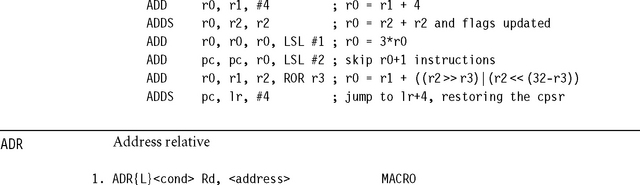
This is not an ARM instruction, but an assembler macro that attempts to set Rd to the value <address> using a pc-relative calculation. The ADR instruction macro always uses a single ARM (or Thumb) instruction. The long-version ADRL always uses two ARM instructions and so can access a wider range of addresses. If the assembler cannot generate an instruction sequence reaching the address, then it will generate an error.
The following example shows how to call the function pointed to by r9. We use ADR to set lr to the return address; in this case, it will assemble to ADD lr, pc, #4. Recall that pc reads as the address of the current instruction plus eight in this case.
![]() If the operation updates the cpsr and Rd is not pc, then N = <Negative>, Z = <Zero>, C = <shifter_C> (see Table A.3), V is preserved.
If the operation updates the cpsr and Rd is not pc, then N = <Negative>, Z = <Zero>, C = <shifter_C> (see Table A.3), V is preserved.
![]() If Rd is pc, then the instruction effects a jump to the calculated address. If the operation updates the cpsr, then the processor mode must have an spsr; in this case, the cpsr is set to the value of the spsr.
If Rd is pc, then the instruction effects a jump to the calculated address. If the operation updates the cpsr, then the processor mode must have an spsr; in this case, the cpsr is set to the value of the spsr.
![]() If Rn or Rm is pc, then the value used is the address of the instruction plus eight bytes.
If Rn or Rm is pc, then the value used is the address of the instruction plus eight bytes.
![]() The cpsr is updated: N = <Negative>, Z = <Zero>, C = <shifter_C> (see Table A.3).
The cpsr is updated: N = <Negative>, Z = <Zero>, C = <shifter_C> (see Table A.3).
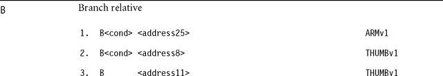
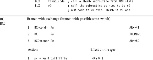
Branches to the given address or label. The address is stored as a relative offset.
![]() If the operation updates the cpsr and Rd is not pc, then N = <Negative>, Z = <Zero>, C = <shifter_C> (see Table A.3), V is preserved.
If the operation updates the cpsr and Rd is not pc, then N = <Negative>, Z = <Zero>, C = <shifter_C> (see Table A.3), V is preserved.
![]() If Rd is pc, then the instruction effects a jump to the calculated address. If the operation updates the cpsr, then the processor mode must have an spsr; in this case, the cpsr is set to the value of the spsr.
If Rd is pc, then the instruction effects a jump to the calculated address. If the operation updates the cpsr, then the processor mode must have an spsr; in this case, the cpsr is set to the value of the spsr.
![]() If Rn or Rm is pc, then the value used is the address of the instruction plus eight bytes.
If Rn or Rm is pc, then the value used is the address of the instruction plus eight bytes.
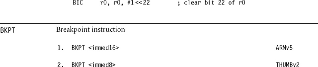
The breakpoint instruction causes a prefetch data abort, unless overridden by debug hardware. The ARM ignores the immediate value. This immediate can be used to hold debug information such as the breakpoint number.
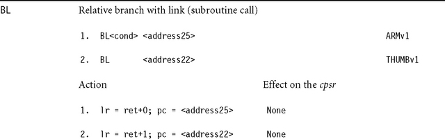
![]() These instructions set lr to the address of the following instruction ret plus the current cpsr T-bit setting. Therefore you can return from the subroutine using BX lr to resume execution address and ARM or Thumb state.
These instructions set lr to the address of the following instruction ret plus the current cpsr T-bit setting. Therefore you can return from the subroutine using BX lr to resume execution address and ARM or Thumb state.
![]()
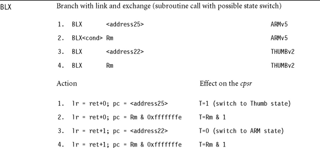
![]() These instructions set lr to the address of the following instruction ret plus the current cpsr T-bit setting. Therefore you can return from the subroutine using BX lr to resume execution address and ARM or Thumb state.
These instructions set lr to the address of the following instruction ret plus the current cpsr T-bit setting. Therefore you can return from the subroutine using BX lr to resume execution address and ARM or Thumb state.
![]() Rm & 3 must not be 2. This would cause a branch to an unaligned ARM instruction.
Rm & 3 must not be 2. This would cause a branch to an unaligned ARM instruction.
![]()
![]() If Rm is pc and the instruction is word aligned, then Rm takes the value of the current instruction plus eight in ARM state or plus four in Thumb state.
If Rm is pc and the instruction is word aligned, then Rm takes the value of the current instruction plus eight in ARM state or plus four in Thumb state.
![]() Rm & 3 must not be 2. This would cause a branch to an unaligned ARM instruction.
Rm & 3 must not be 2. This would cause a branch to an unaligned ARM instruction.
![]() If the JE (Java Enable) configuration bit is clear, then BXJ behaves as a BX. Otherwise, the behavior is defined by the architecture of the Java Extension hardware. Typically it sets J = 1 in the cpsr and starts executing Java instructions from a general purpose register designated as the Java program counter jpc.
If the JE (Java Enable) configuration bit is clear, then BXJ behaves as a BX. Otherwise, the behavior is defined by the architecture of the Java Extension hardware. Typically it sets J = 1 in the cpsr and starts executing Java instructions from a general purpose register designated as the Java program counter jpc.
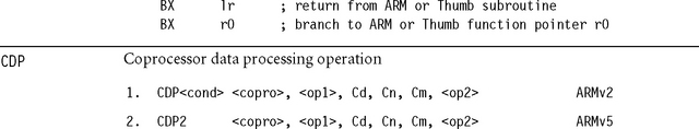
These instructions initiate a coprocessor-dependent operation. <copro> is the number of the coprocessor in the range p0 to p15. The core takes an undefined instruction trap if the coprocessor is not present. The coprocessor operation specifiers <op1> and <op2>, and the coprocessor register numbers Cd, Cn, Cm, are interpreted by the coprocessor and ignored by the ARM. CDP2 provides an additional set of coprocessor instructions.

Rn is set to the maximum left shift that can be applied to Rm without unsigned overflow. Equivalently, this is the number of zeros above the highest one in the binary representation of Rm. If Rm = 0, then Rn is set to 32. The following example normalizes the value in r0 so that bit 31 is set.
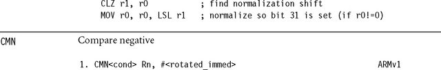
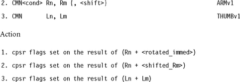
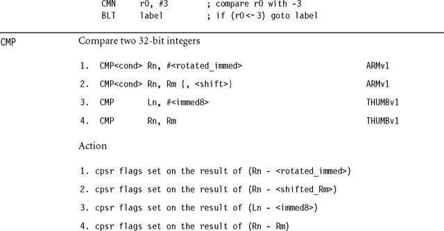
![]() In the cpsr: N = <Negative>, Z = <Zero>, C = <Unsigned-Overflow>, V = <SignedOverflow>. These are the same flags as generated by CMP with the second operand negated.
In the cpsr: N = <Negative>, Z = <Zero>, C = <Unsigned-Overflow>, V = <SignedOverflow>. These are the same flags as generated by CMP with the second operand negated.
![]() If Rn or Rm is pc, then the value used is the address of the instruction plus eight bytes.
If Rn or Rm is pc, then the value used is the address of the instruction plus eight bytes.
![]() In the cpsr: N = <Negative>, Z = <Zero>, C = <NoUnsigned-Overflow>, V = <SignedOverflow>. The carry flag is set this way because the subtract x – y is implemented as the add x + ∼y + 1. The carry flag is one if x + ∼y + 1 overflows. This happens when x ≥ y (equivalently when x – y doesn’t overflow).
In the cpsr: N = <Negative>, Z = <Zero>, C = <NoUnsigned-Overflow>, V = <SignedOverflow>. The carry flag is set this way because the subtract x – y is implemented as the add x + ∼y + 1. The carry flag is one if x + ∼y + 1 overflows. This happens when x ≥ y (equivalently when x – y doesn’t overflow).
![]() If Rn or Rm is pc, then the value used is the address of the instruction plus eight bytes for ARM instructions, or plus four bytes for Thumb instructions.
If Rn or Rm is pc, then the value used is the address of the instruction plus eight bytes for ARM instructions, or plus four bytes for Thumb instructions.
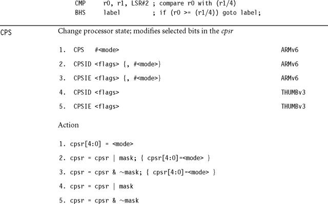
Bits are set in mask according to letters in the <flags> value as in Table A.4. The ID (interrupt disable) variants mask interrupts by setting cpsr bits. The IE (interrupt enable) variants unmask interrupts by clearing cpsr bits.
Table A.4
| Character | cpsr bit affected | Bit set in mask |
| a | imprecise data Abort mask bit | 0x100 = 1<<8 |
| i | IRQ mask bit | 0x080 = 1<<7 |
| f | FIQ mask bit | 0x040 = 1<<6 |
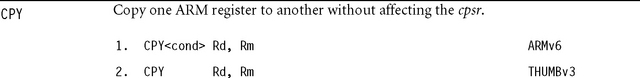
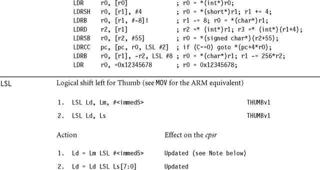
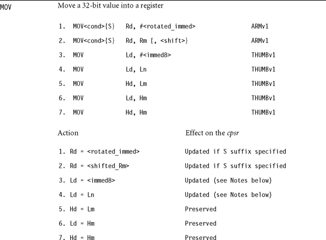
This assembles to MOV<cond> Rd, Rm except in the case of Thumb where Rd and Rm are low registers in the range r0 to r7. Then it is a new operation that sets Rd=Rm without affecting the cpsr.
![]() If the operation updates the cpsr and Rd is not pc, then N = <Negative>, Z = <Zero>, C = <shifter_C> (see Table A.3), V is preserved.
If the operation updates the cpsr and Rd is not pc, then N = <Negative>, Z = <Zero>, C = <shifter_C> (see Table A.3), V is preserved.
![]() If Rd is pc, then the instruction effects a jump to the calculated address. If the operation updates the cpsr, then the processor mode must have an spsr; in this case, the cpsr is set to the value of the spsr.
If Rd is pc, then the instruction effects a jump to the calculated address. If the operation updates the cpsr, then the processor mode must have an spsr; in this case, the cpsr is set to the value of the spsr.
![]() If Rn or Rm is pc, then the value used is the address of the instruction plus eight bytes.
If Rn or Rm is pc, then the value used is the address of the instruction plus eight bytes.
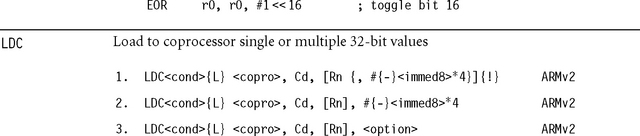

These instructions initiate a memory read, transferring data to the given coprocessor. <copro> is the number of the coprocessor in the range p0 to p15. The core takes an undefined instruction trap if the coprocessor is not present. The memory read consists of a sequence of words from sequentially increasing addresses. The initial address is specified by the addressing mode in Table A.5. The coprocessor controls the number of words transferred, up to a maximum limit of 16 words. The fields {L} and Cd are interpreted by the coprocessor and ignored by the ARM. Typically Cd specifies the destination coprocessor register for the transfer. The <option> field is an eight-bit integer enclosed in {}. Its interpretation is coprocessor dependent.
Table A.5
| Addressing format | Address accessed | Value written back to Rn |
| [Rn {,# {-}<immed>}] | Rn + {{-}<immed>} | Rn preserved |
| [Rn {,# {-}<immed>}]! | Rn + {{-}<immed>} | Rn + {{-}<immed>} |
| [Rn], # {-}<immed> | Rn | Rn + {-}<immed> |
| [Rn], <option> | Rn | Rn preserved |
If the address is not a multiple of four, then the access is unaligned. The restrictions on unaligned accesses are the same as for LDM.
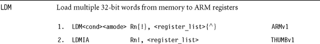
These instructions load multiple words from sequential memory addresses. The <register_list> specifies a list of registers to load, enclosed in curly brackets {}. Although the assembler allows you to specify the registers in the list in any order, the order is not stored in the instruction, so it is good practice to write the list in increasing order of register number because this is the usual order of the memory transfer.
The following pseudocode shows the normal action of LDM. We use <register_list>[i] to denote the register appearing at position i in the list, starting at 0 for the first register. This assumes that the list is in order of increasing register number.
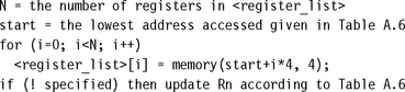
Note that memory(a, 4) returns the four bytes at address a packed according to the current processor data endianness. If a is not a multiple of four, then the load is unaligned. Because the behavior of an unaligned load depends on the architecture revision, memory system, and system coprocessor (CP15) configuration, it’s best to avoid unaligned loads if possible. Assuming that the external memory system does not abort unaligned loads, then the following rules usually apply:
![]() If the core has a system coprocessor and bit 1 (A-bit) or bit 22 (U-bit) of CP15:c1:c0:0 is set, then unaligned load multiples cause an alignment fault data abort exception.
If the core has a system coprocessor and bit 1 (A-bit) or bit 22 (U-bit) of CP15:c1:c0:0 is set, then unaligned load multiples cause an alignment fault data abort exception.
Table A.6 lists the possible addressing modes specified by <amode>. If you specify the !, then the base address register is updated according to Table A.6; otherwise it is preserved. Note that the lowest register number is always read from the lowest address.
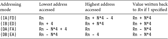
The first half of the addressing mode mnemonics stands for Increment After, Increment Before, Decrement After, and Decrement Before, respectively. Increment modes load the registers sequentially forward, starting from address Rn (increment after) or Rn + 4 (increment before). Decrement modes have the same effect as if you loaded the register list backwards from sequentially descending memory addresses, starting from address Rn (decrement after) or Rn – 4 (decrement before).
The second half of the addressing mode mnemonics stands for the stack type you can implement with that address mode: Full Descending, Empty Descending, Full Ascending, and Empty Ascending, With a full stack, Rn points to the last stacked value; with an empty stack, Rn points to the first unused stack location. ARM stacks are usually full descending.
You should use full descending or empty ascending stacks by preference, since LDC also supports these addressing modes.
![]() For Thumb (format 2), Rn and the register list registers must be in the range r0 to r7.
For Thumb (format 2), Rn and the register list registers must be in the range r0 to r7.
![]() The number of registers N in the list must be nonzero.
The number of registers N in the list must be nonzero.
![]() Rn must not appear in the register list if ! (writeback) is specified.
Rn must not appear in the register list if ! (writeback) is specified.
![]() If pc appears in the register list, then on ARMv5 and above the processor performs a BX to the loaded address. For ARMv4 and below, the processor branches to the loaded address.
If pc appears in the register list, then on ARMv5 and above the processor performs a BX to the loaded address. For ARMv4 and below, the processor branches to the loaded address.
![]() If
If ![]() is specified, then the operation is modified. The processor must not be in user or system mode. If pc is not in the register list, then the registers appearing in the register list refer to the user mode versions of the registers and writeback must not be specified. If pc is in the register list, then the spsr is copied to the cpsr in addition to the standard operation.
is specified, then the operation is modified. The processor must not be in user or system mode. If pc is not in the register list, then the registers appearing in the register list refer to the user mode versions of the registers and writeback must not be specified. If pc is in the register list, then the spsr is copied to the cpsr in addition to the standard operation.
![]() The time order of the memory accesses may depend on the implementation. Be careful when using a load multiple to access I/O locations where the access order matters. If the order matters, then check that the memory locations are marked as I/O in the page tables, do not cross page boundaries, and do not use pc in the register list.
The time order of the memory accesses may depend on the implementation. Be careful when using a load multiple to access I/O locations where the access order matters. If the order matters, then check that the memory locations are marked as I/O in the page tables, do not cross page boundaries, and do not use pc in the register list.
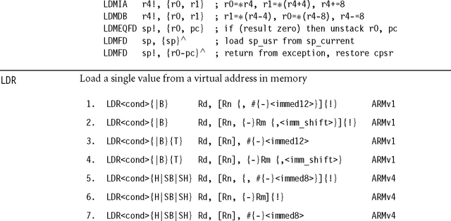
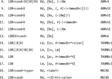
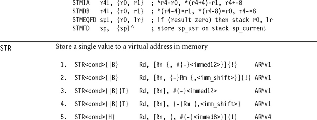
Formats 1 to 17 load a single data item of the type specified by the opcode suffix, using a preindexed or postindexed addressing mode. Tables A.7 and A.8 show the different addressing modes and data types.
Table A.7
| Addressing format | Address a accessed | Value written back to Rn |
| [Rn {,#{-}<immed>}] | Rn + {{-}<immed>} | Rn preserved |
| [Rn {,#{-}<immed>}]! | Rn + {{-}<immed>} | Rn + {{-}<immed>} |
| [Rn, {-}Rm {,<shift>}] | Rn + {-}<shifted_Rm> | Rn preserved |
| [Rn, {-}Rm {,<shift>}]! | Rn + {-}<shifted_Rm> | Rn + {-}<shifted_Rm> |
| [Rn], #{-}<immed> | Rn | Rn + {-}<immed> |
| [Rn], {-}Rm {,<shift>} | Rn | Rn + {-}<shifted_Rm> |
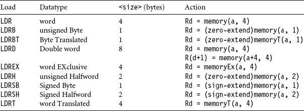
In Table A.8 memory(a, n) reads n sequential bytes from address a. The bytes are packed according to the configured processor data endianness. The function memoryT(a, n) performs the same access but with user mode privileges, regardless of the current processor mode. The function memoryEx(a, n) used by LDREX performs the access and marks the access as exclusive. If address a has the shared TLB attribute, then this marks address a as exclusive to the current processor and clears any other exclusive addresses for this processor.
Otherwise the processor remembers that there is an outstanding exclusive access. Exclusivity only affects the action of the STREX instruction.
If address a is not a multiple of <size>, then the load is unaligned. Because the behavior of an unaligned load depends on the architecture revision, memory system, and system coprocessor (CP15) configuration, it’s best to avoid unaligned loads if possible. Assuming that the external memory system does not abort unaligned loads, then the following rules usually apply. In the rules, A is bit 1 of system coprocessor register CP15:c1:c0:0, and U is bit 22 of CP15:c1:c0:0, introduced in ARMv6. If there is no system coprocessor, then A = U = 0.
![]() If A = 1, then unaligned loads cause an alignment fault data abort exception except that word-aligned double-word loads are supported if U = 1.
If A = 1, then unaligned loads cause an alignment fault data abort exception except that word-aligned double-word loads are supported if U = 1.
![]() If A = 0 and U = 1, then unaligned loads are supported for LDR{|T|H|SH}. Word-aligned loads are supported for LDRD. A non-word-aligned LDRD generates an alignment fault data abort.
If A = 0 and U = 1, then unaligned loads are supported for LDR{|T|H|SH}. Word-aligned loads are supported for LDRD. A non-word-aligned LDRD generates an alignment fault data abort.
![]() If A = 0 and U = 0, then LDR and LDRT return the value memory(a & ∼3, 4) ROR ((a&3)*8). All other unaligned operations are unpredictable but do not generate an alignment fault.
If A = 0 and U = 0, then LDR and LDRT return the value memory(a & ∼3, 4) ROR ((a&3)*8). All other unaligned operations are unpredictable but do not generate an alignment fault.
Format 18 generates a pc-relative load accessing the address specified by <label>. In other words, it assembles to LDR<cond><type> Rd, [pc, #<offset>] whenever this instruction is supported and <offset>=<label>-pc is in range.
Format 19 generates an instruction to move the given 32-bit value to the register Rd. Usually the instruction is LDR<cond> Rd, [pc, #<offset>], where the 32-bit value is stored in a literal pool at address pc+<offset>.
![]() For double-word loads (formats 9 to 12), Rd must be even and in the range r0 to r12.
For double-word loads (formats 9 to 12), Rd must be even and in the range r0 to r12.
![]() If the addressing mode updates Rn, then Rd and Rn must be distinct.
If the addressing mode updates Rn, then Rd and Rn must be distinct.
![]() If Rd is pc, then <size> must be 4. Up to ARMv4, the core branches to the loaded address. For ARMv5 and above, the core performs a BX to the loaded address.
If Rd is pc, then <size> must be 4. Up to ARMv4, the core branches to the loaded address. For ARMv5 and above, the core performs a BX to the loaded address.
![]() If Rn is pc, then the addressing mode must not update Rn. The value used for Rn is the address of the instruction plus eight bytes for ARM or four bytes for Thumb.
If Rn is pc, then the addressing mode must not update Rn. The value used for Rn is the address of the instruction plus eight bytes for ARM or four bytes for Thumb.
![]() For ARMv6 use LDREX and STREX to implement semaphores rather than SWP.
For ARMv6 use LDREX and STREX to implement semaphores rather than SWP.
![]() The cpsr is updated: N = <Negative>, Z = <Zero>, C = <shifter_C> (see Table A.3).
The cpsr is updated: N = <Negative>, Z = <Zero>, C = <shifter_C> (see Table A.3).

![]() The cpsr is updated: N = <Negative>, Z = <Zero>, C = <shifter_C> (see Table A.3).
The cpsr is updated: N = <Negative>, Z = <Zero>, C = <shifter_C> (see Table A.3).
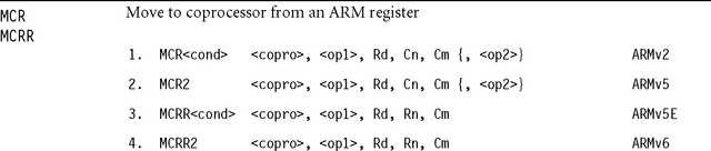
These instructions transfer the value of ARM register Rd to the indicated coprocessor. Formats 3 and 4 also transfer a second register Rn. <copro> is the number of the coprocessor in the range p0 to p15. The core takes an undefined instruction trap if the coprocessor is not present. The coprocessor operation specifiers <op1> and <op2>, and the coprocessor register numbers Cn, Cm, are interpreted by the coprocessor, and ignored by the ARM. Rd and Rn must not be pc. Coprocessor p15 controls memory management options. See Chapters 13 and 14 for descriptions of the MPU and MMU memory management units. For example, the following code sequence enables alignment fault checking:
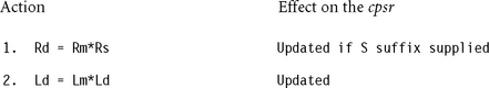
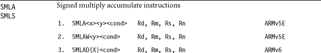
![]() Rd is set to the lower 32 bits of the result.
Rd is set to the lower 32 bits of the result.
![]() Rd, Rm, Rs, Rn must not be pc.
Rd, Rm, Rs, Rn must not be pc.
![]() Rd and Rm must be different registers.
Rd and Rm must be different registers.
![]() Implementations may terminate early on the value of the Rs operand. For this reason use small or constant values for Rs where possible. See Appendix D.
Implementations may terminate early on the value of the Rs operand. For this reason use small or constant values for Rs where possible. See Appendix D.
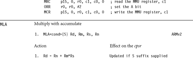
![]() If the cpsr is updated, then N = <Negative>, Z = <Zero>, C is unpredictable, and V is preserved. Avoid using the instruction MLAS because implementations often impose penalty cycles for this operation. Instead use MLA followed by a compare, and schedule the compare to avoid multiply result use interlocks.
If the cpsr is updated, then N = <Negative>, Z = <Zero>, C is unpredictable, and V is preserved. Avoid using the instruction MLAS because implementations often impose penalty cycles for this operation. Instead use MLA followed by a compare, and schedule the compare to avoid multiply result use interlocks.
![]() If the operation updates the cpsr and Rd is not pc, then N = <Negative>, Z = <Zero>, C= <shifter_C> (see Table A.3), and V is preserved.
If the operation updates the cpsr and Rd is not pc, then N = <Negative>, Z = <Zero>, C= <shifter_C> (see Table A.3), and V is preserved.
![]() If Rd or Hd is pc, then the instruction effects a jump to the calculated address. If the operation updates the cpsr, then the processor mode must have an spsr; in this case, the cpsr is set to the value of the spsr.
If Rd or Hd is pc, then the instruction effects a jump to the calculated address. If the operation updates the cpsr, then the processor mode must have an spsr; in this case, the cpsr is set to the value of the spsr.
![]() If Rm is pc, then the value used is the address of the instruction plus eight bytes.
If Rm is pc, then the value used is the address of the instruction plus eight bytes.
![]() If Hm is pc, then the value used is the address of the instruction plus four bytes.
If Hm is pc, then the value used is the address of the instruction plus four bytes.

These instructions transfer a 32-bit value from the indicated coprocessor to the ARM register Rd. Formats 3 and 4 also transfer a second 32-bit value to Rn. <copro> is the number of the coprocessor in the range p0 to p15. The core takes an undefined instruction trap if the coprocessor is not present. The coprocessor operation specifiers <op1> and <op2>, and the coprocessor register numbers Cn, Cm, are interpreted by the coprocessor and ignored by the ARM. For formats 1 and 2, if Rd is pc, then the top four bits of the cpsr (the NZCV condition code flags) are set from the top four bits of the 32-bit value transferred; pc is not affected. For other formats, Rd and Rn must be distinct and not pc.
Coprocessor p15 controls memory management options (see Chapters 12 and 13). For example, the following instruction reads the main ID register from p15:
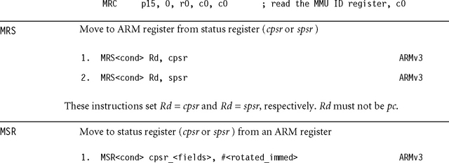
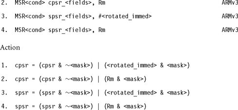
These instructions alter selected bytes of the cpsr or spsr according to the value of <mask>. The <fields> specifier is a sequence of one or more letters, determining which bytes of <mask> are set. See Table A.9.
Table A.9
Format of the <fields> specifier.
| <fields> letter | Meaning | Bits set in <mask> |
| c | Control byte | 0x000000ff |
| x | extension byte | 0x0000ff00 |
| s | Status byte | 0x00ff0000 |
| f | Flags byte | 0xff000000 |
Some old ARM toolkits allowed cpsr or cpsr_all in place of cpsr_fsxc. They also used cpsr_flg and cpsr_ctl in place of cpsr_f and cpsr_c, respectively. These formats, and the spsr equivalents, are obsolete, so you should not use them. The following example changes to system mode and enables IRQ, which is useful in a reentrant interrupt handler:

![]() Rd or Ld is set to the lower 32 bits of the result.
Rd or Ld is set to the lower 32 bits of the result.
![]() Rd and Rm must be different registers. Similarly Ld and Lm must be different.
Rd and Rm must be different registers. Similarly Ld and Lm must be different.
![]() Implementations may terminate early on the value of the Rs or Ld operand. For this reason use small or constant values for Rs or Ld where possible.
Implementations may terminate early on the value of the Rs or Ld operand. For this reason use small or constant values for Rs or Ld where possible.
![]() If the cpsr is updated, then N = <Negative>, Z = <Zero>, C is unpredictable, and V is preserved. Avoid using the instruction MULS because implementations often impose penalty cycles for this operation. Instead use MUL followed by a compare, and schedule the compare, to avoid multiply result use interlocks.
If the cpsr is updated, then N = <Negative>, Z = <Zero>, C is unpredictable, and V is preserved. Avoid using the instruction MULS because implementations often impose penalty cycles for this operation. Instead use MUL followed by a compare, and schedule the compare, to avoid multiply result use interlocks.
![]() If the operation updates the cpsr and Rd is not pc, then N = <Negative>, Z = <Zero>, C = <shifter_C> (see Table A.3), and V is preserved.
If the operation updates the cpsr and Rd is not pc, then N = <Negative>, Z = <Zero>, C = <shifter_C> (see Table A.3), and V is preserved.
![]() If Rd is pc, then the instruction effects a jump to the calculated address. If the operation updates the cpsr, then the processor mode must have an spsr; in this case, the cpsr is set to the value of the spsr.
If Rd is pc, then the instruction effects a jump to the calculated address. If the operation updates the cpsr, then the processor mode must have an spsr; in this case, the cpsr is set to the value of the spsr.
![]() If Rm is pc, then the value used is the address of the instruction plus eight bytes.
If Rm is pc, then the value used is the address of the instruction plus eight bytes.
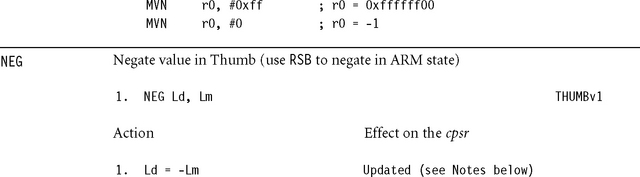
![]() The cpsr is updated: N = <Negative>, Z = <Zero>, C = <NoUnsignedOverflow>, V = <SignedOverflow>. Note that Z = C and V = (Ld==0×80000000).
The cpsr is updated: N = <Negative>, Z = <Zero>, C = <NoUnsignedOverflow>, V = <SignedOverflow>. Note that Z = C and V = (Ld==0×80000000).
![]() This is the same as the operation RSBS Ld, Lm, #0 in ARM state.
This is the same as the operation RSBS Ld, Lm, #0 in ARM state.

This is not an ARM instruction. It is an assembly macro that produces an instruction having no effect other than advancing the pc as normal. In ARM state it assembles to MOV r0,r0. In Thumb state it assembles to MOV r8,r8. The operation is not guaranteed to take one processor cycle. In particular, if you use NOP after a load of r0, then the operation may cause pipeline interlocks.
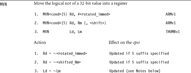
![]() If the operation updates the cpsr and Rd is not pc, then N = <Negative>, Z = <Zero>, C = <shifter_C> (see Table A.3), and V is preserved.
If the operation updates the cpsr and Rd is not pc, then N = <Negative>, Z = <Zero>, C = <shifter_C> (see Table A.3), and V is preserved.
![]() If Rd is pc, then the instruction effects a jump to the calculated address. If the operation updates the cpsr, then the processor mode must have an spsr, in this case, the cpsr is set to the value of the spsr.
If Rd is pc, then the instruction effects a jump to the calculated address. If the operation updates the cpsr, then the processor mode must have an spsr, in this case, the cpsr is set to the value of the spsr.
![]() If Rn or Rm is pc, then the value used is the address of the instruction plus eight bytes.
If Rn or Rm is pc, then the value used is the address of the instruction plus eight bytes.
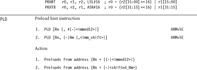
This instruction does not affect the processor registers (other than advancing pc). It merely hints that the programmer is likely to read from the given address in future. A cached processor may take this as a hint to load the cache line containing the address into the cache. The instruction should not generate a data abort or any other memory system error. If Rn is pc, then the value used for Rn is the address of the instruction plus eight. Rm must not be pc.

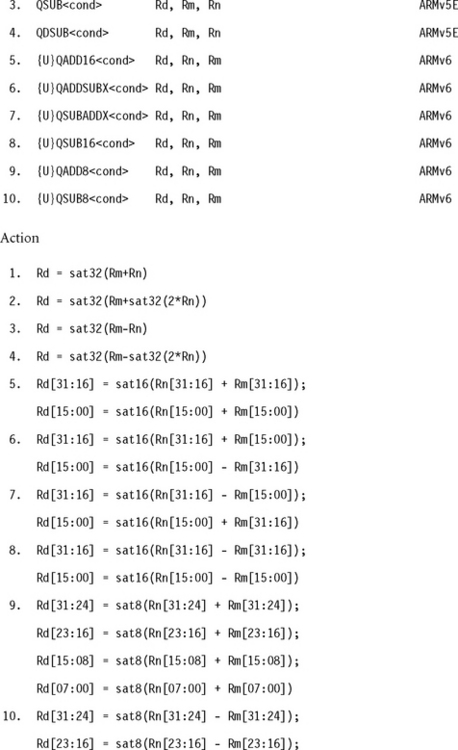
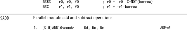
![]()
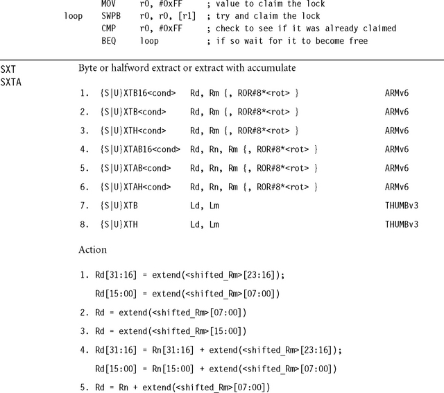
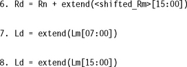
![]() The operations are signed unless the U prefix is present. For signed operations, satN(x) saturates x to the range −2N−1 ≤ x < 2N−1. For unsigned operations, satN(x) saturates x to the range 0 ≤ x < 2N.
The operations are signed unless the U prefix is present. For signed operations, satN(x) saturates x to the range −2N−1 ≤ x < 2N−1. For unsigned operations, satN(x) saturates x to the range 0 ≤ x < 2N.
![]() The cpsr Q-flag is set if saturation occurred; otherwise it is preserved.
The cpsr Q-flag is set if saturation occurred; otherwise it is preserved.
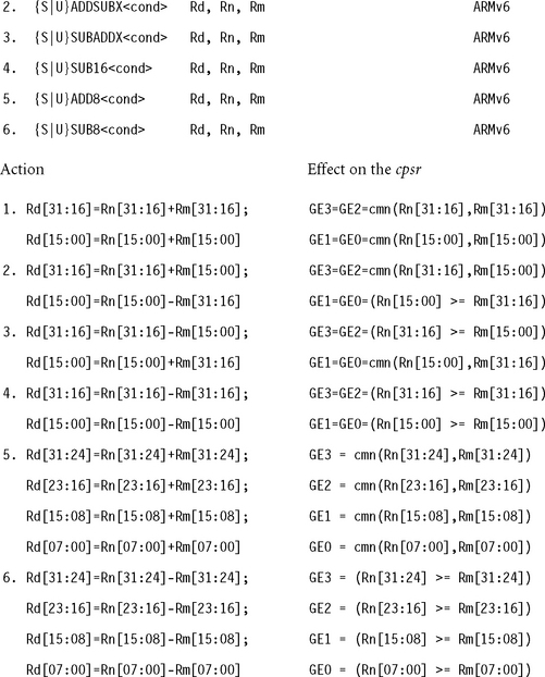
![]() The X operations are useful for packed complex numbers. The following examples assume bits [15:00] hold the real part and [31:16] the imaginary part.
The X operations are useful for packed complex numbers. The following examples assume bits [15:00] hold the real part and [31:16] the imaginary part.
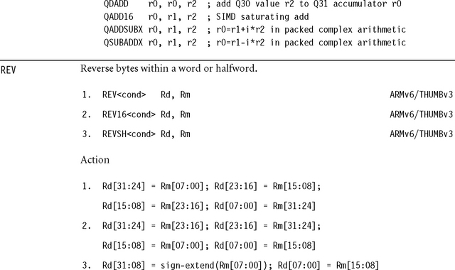
![]() For Thumb, Rd, Rm must be in the range r0 to r7 and <cond> cannot be specified.
For Thumb, Rd, Rm must be in the range r0 to r7 and <cond> cannot be specified.
![]() These instructions are useful to convert big-endian data to little-endian and vice versa.
These instructions are useful to convert big-endian data to little-endian and vice versa.
![]() The cpsr is updated: N = <Negative>, Z = <Zero>, C = <shifter_C> (see Table A.3).
The cpsr is updated: N = <Negative>, Z = <Zero>, C = <shifter_C> (see Table A.3).
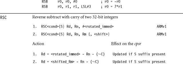
![]() If the operation updates the cpsr and Rd is not pc, then N = <Negative>, Z = <Zero>, C = <NoUnsignedOverflow>, and V = <SignedOverflow>. The carry flag is set this way because the subtract x – y is implemented as the add x + ∼y + 1. The carry flag is one if x + ∼y + 1 overflows. This happens when x ≥ y, when x – y doesn’t overflow.
If the operation updates the cpsr and Rd is not pc, then N = <Negative>, Z = <Zero>, C = <NoUnsignedOverflow>, and V = <SignedOverflow>. The carry flag is set this way because the subtract x – y is implemented as the add x + ∼y + 1. The carry flag is one if x + ∼y + 1 overflows. This happens when x ≥ y, when x – y doesn’t overflow.
![]() If Rd is pc, then the instruction effects a jump to the calculated address. If the operation updates the cpsr, then the processor mode must have an spsr in this case, the cpsr is set to the value of the spsr.
If Rd is pc, then the instruction effects a jump to the calculated address. If the operation updates the cpsr, then the processor mode must have an spsr in this case, the cpsr is set to the value of the spsr.
![]() If Rn or Rm is pc, then the value used is the address of the instruction plus eight bytes.
If Rn or Rm is pc, then the value used is the address of the instruction plus eight bytes.
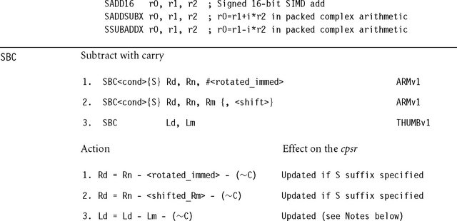
![]() If the operation updates the cpsr and Rd is not pc, then N = <Negative>, Z = <Zero>, C = <NoUnsignedOverflow>, V = <SignedOverflow>. The carry flag is set this way because the subtract x – y – ∼C is implemented as the add x + ∼y + C. The carry flag is one if x + ∼y + C overflows. This happens when x – y – ∼C doesn’t overflow.
If the operation updates the cpsr and Rd is not pc, then N = <Negative>, Z = <Zero>, C = <NoUnsignedOverflow>, V = <SignedOverflow>. The carry flag is set this way because the subtract x – y – ∼C is implemented as the add x + ∼y + C. The carry flag is one if x + ∼y + C overflows. This happens when x – y – ∼C doesn’t overflow.
![]() If Rd is pc, then the instruction effects a jump to the calculated address. If the operation updates the cpsr, then the processor mode must have an spsr; in this case the cpsr is set to the value of the spsr.
If Rd is pc, then the instruction effects a jump to the calculated address. If the operation updates the cpsr, then the processor mode must have an spsr; in this case the cpsr is set to the value of the spsr.
![]() If Rn or Rm is pc, then the value used is the address of the instruction plus eight bytes.
If Rn or Rm is pc, then the value used is the address of the instruction plus eight bytes.
The following example negates a 64-bit integer where r0 is the low 32 bits and r1 the high 32 bits.
![]() If you specify the S prefix, then all comparisons are signed. The cmn(x,y) function returns x ≥ –y or equivalently x + y ≥ 0.
If you specify the S prefix, then all comparisons are signed. The cmn(x,y) function returns x ≥ –y or equivalently x + y ≥ 0.
![]() If you specify the U prefix, then all comparisons are unsigned. The cmn(x,y) function returns x ≥ (unsigned)(–y) or equivalently if the x + y operation produces a carry.
If you specify the U prefix, then all comparisons are unsigned. The cmn(x,y) function returns x ≥ (unsigned)(–y) or equivalently if the x + y operation produces a carry.
![]() Rd, Rn, and Rm must not be pc.
Rd, Rn, and Rm must not be pc.
![]() The X operations are useful for packed complex numbers. The following examples assume bits [15:00] hold the real part and [31:16] the imaginary part.
The X operations are useful for packed complex numbers. The following examples assume bits [15:00] hold the real part and [31:16] the imaginary part.
![]() If the operation updates the cpsr and Rd is not pc, then N = <Negative>, Z = <Zero>, C = <NoUnsignedOverflow>, V = <SignedOverflow>. The carry flag is set this way because the subtract x – y – ∼C is implemented as the add x + ∼y + C. The carry flag is one if x + ∼y + C overflows. This happens when x – y – ∼C doesn’t overflow.
If the operation updates the cpsr and Rd is not pc, then N = <Negative>, Z = <Zero>, C = <NoUnsignedOverflow>, V = <SignedOverflow>. The carry flag is set this way because the subtract x – y – ∼C is implemented as the add x + ∼y + C. The carry flag is one if x + ∼y + C overflows. This happens when x – y – ∼C doesn’t overflow.
![]() If Rd is pc, then the instruction effects a jump to the calculated address. If the operation updates the cpsr, then the processor mode must have an spsr. In this case the cpsr is set to the value of the spsr.
If Rd is pc, then the instruction effects a jump to the calculated address. If the operation updates the cpsr, then the processor mode must have an spsr. In this case the cpsr is set to the value of the spsr.
![]() If Rn or Rm is pc, then the value used is the address of the instruction plus eight bytes.
If Rn or Rm is pc, then the value used is the address of the instruction plus eight bytes.
The following example implements a 64-bit subtract:


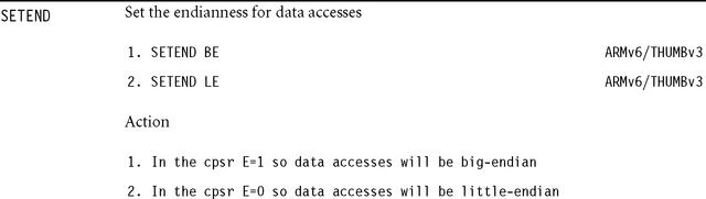
![]() ARMv6 uses a byte-invariant endianness model. This means that byte loads and stores are not affected by the configured endianess. For little-endian data access the byte at the lowest address appears in the least significant byte of the loaded word. For big-endian data accesses the byte at the lowest address appears in the most significant byte of the loaded word.
ARMv6 uses a byte-invariant endianness model. This means that byte loads and stores are not affected by the configured endianess. For little-endian data access the byte at the lowest address appears in the least significant byte of the loaded word. For big-endian data accesses the byte at the lowest address appears in the most significant byte of the loaded word.
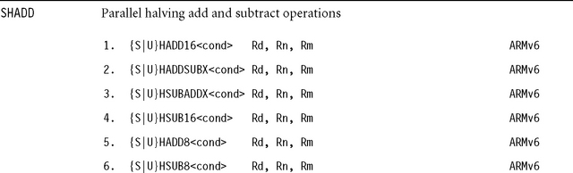
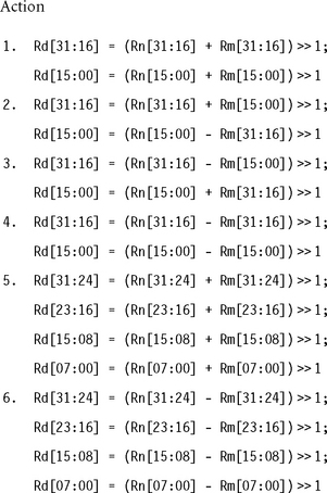
![]() If you use the S prefix, then all operations are signed and values are sign-extended before the addition.
If you use the S prefix, then all operations are signed and values are sign-extended before the addition.
![]() If you use the U prefix, then all operations are unsigned and values are zero-extended before the addition.
If you use the U prefix, then all operations are unsigned and values are zero-extended before the addition.
![]() Rd, Rn, and Rm must not be pc.
Rd, Rn, and Rm must not be pc.
![]() These operations provide parallel arithmetic that cannot overflow, which is useful for DSP processing of normalized signals.
These operations provide parallel arithmetic that cannot overflow, which is useful for DSP processing of normalized signals.
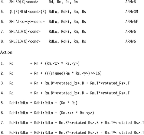
![]() Rm.B is shorthand for (sign-extend)Rm[15:00], the bottom 16 bits of Rm.
Rm.B is shorthand for (sign-extend)Rm[15:00], the bottom 16 bits of Rm.
![]() Rm.T is shorthand for (sign-extend)Rm[31:16], the top 16 bits of Rm.
Rm.T is shorthand for (sign-extend)Rm[31:16], the top 16 bits of Rm.
![]() <rotated_Rs> is Rs if you do not specify the X suffix or Rs ROR 16 if you do specify the X suffix.
<rotated_Rs> is Rs if you do not specify the X suffix or Rs ROR 16 if you do specify the X suffix.
![]() RdHi and RdLo must be different registers. For format 5, Rm must be a different register from RdHi and RdLo.
RdHi and RdLo must be different registers. For format 5, Rm must be a different register from RdHi and RdLo.
![]() Formats 1 to 4 update the cpsr Q-flag: Q = Q| <SignedOverflow>.
Formats 1 to 4 update the cpsr Q-flag: Q = Q| <SignedOverflow>.
![]() Format 5 implements an unsigned multiply with the U prefix or a signed multiply with the S prefix.
Format 5 implements an unsigned multiply with the U prefix or a signed multiply with the S prefix.
![]() Format 5 updates the cpsr if the S suffix is present: N = RdHi[31], Z = (RdHi==0 && RdLo==0); the C and V flags are unpredictable. Avoid using {U|S}MLALS because implementations often impose penalty cycles for this operation.
Format 5 updates the cpsr if the S suffix is present: N = RdHi[31], Z = (RdHi==0 && RdLo==0); the C and V flags are unpredictable. Avoid using {U|S}MLALS because implementations often impose penalty cycles for this operation.
![]() Implementations may terminate early on the value of Rs. For this reason use small or constant values for Rs where possible.
Implementations may terminate early on the value of Rs. For this reason use small or constant values for Rs where possible.
![]() The X suffix and multiply subtract versions are useful for packed complex numbers. The following examples assume bits [15:00] hold the real part and [31:16] the imaginary part.
The X suffix and multiply subtract versions are useful for packed complex numbers. The following examples assume bits [15:00] hold the real part and [31:16] the imaginary part.
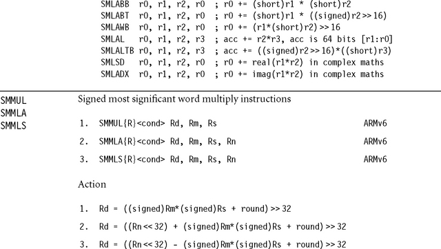
![]() If you specify the R suffix then round = 231; otherwise, round = 0.
If you specify the R suffix then round = 231; otherwise, round = 0.
![]() Rd, Rm, Rs, and Rn must not be pc.
Rd, Rm, Rs, and Rn must not be pc.
![]() Implementations may terminate early on the value of Rs.
Implementations may terminate early on the value of Rs.
![]() For 32-bit DSP algorithms these operations have several advantages over using the high result register from SMLAL: They often take fewer cycles than SMLAL. They also implement rounding, multiply subtract, and don’t require a temporary scratch register for the low 32 bits of result.
For 32-bit DSP algorithms these operations have several advantages over using the high result register from SMLAL: They often take fewer cycles than SMLAL. They also implement rounding, multiply subtract, and don’t require a temporary scratch register for the low 32 bits of result.
![]()
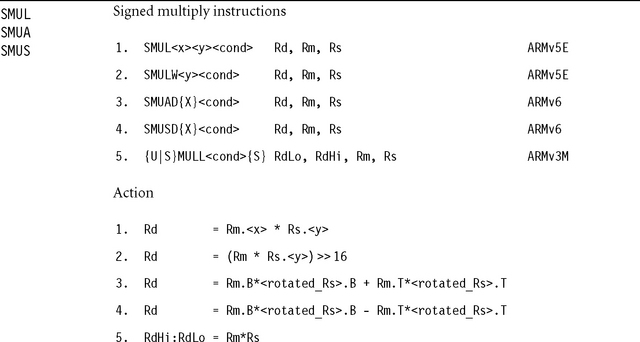
![]() Rm.B is shorthand for (sign-extend)Rm[15:00], the bottom 16 bits of Rm.
Rm.B is shorthand for (sign-extend)Rm[15:00], the bottom 16 bits of Rm.
![]() Rm.Tis shorthand for (sign-extend)Rm[31:16], the top 16 bits of Rm.
Rm.Tis shorthand for (sign-extend)Rm[31:16], the top 16 bits of Rm.
![]() <rotated_Rs> is Rs if you do not specify the X suffix or Rs ROR 16 if you do specify the X suffix.
<rotated_Rs> is Rs if you do not specify the X suffix or Rs ROR 16 if you do specify the X suffix.
![]() RdHi and RdLo must be different registers. For format 5, Rm must be a different register from RdHi and RdLo.
RdHi and RdLo must be different registers. For format 5, Rm must be a different register from RdHi and RdLo.
![]() Format 4 updates the cpsr Q-flag: Q = Q | <SignedOverflow>.
Format 4 updates the cpsr Q-flag: Q = Q | <SignedOverflow>.
![]() Format 5 implements an unsigned multiply with the U prefix or a signed multiply with the S prefix.
Format 5 implements an unsigned multiply with the U prefix or a signed multiply with the S prefix.
![]() Format 5 updates the cpsr if the S suffix is present: N = RdHi[31], Z = (RdHi==0 && RdLo==0); the C and V flags are unpredictable. Avoid using {S|U}MULLS because implementations often impose penalty cycles for this operation.
Format 5 updates the cpsr if the S suffix is present: N = RdHi[31], Z = (RdHi==0 && RdLo==0); the C and V flags are unpredictable. Avoid using {S|U}MULLS because implementations often impose penalty cycles for this operation.
![]() Implementations may terminate early on the value of Rs. For this reason use small or constant values for Rs where possible.
Implementations may terminate early on the value of Rs. For this reason use small or constant values for Rs where possible.
![]() The X suffix and multiply subtract versions are useful for packed complex numbers. The following examples assume bits [15:00] hold the real part and [31:16] the imaginary part.
The X suffix and multiply subtract versions are useful for packed complex numbers. The following examples assume bits [15:00] hold the real part and [31:16] the imaginary part.
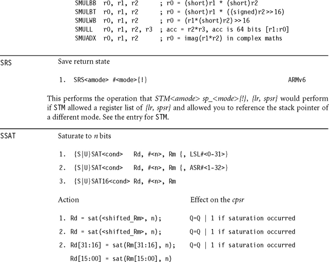
![]() If you specify the S prefix, then sat(x, n) saturates the signed value x to a signed n-bit value in the range −2n−1 ≤ x < 2n–1. n is encoded as 1 + <immed5> for SAT and 1 + <immed4> for SAT16.
If you specify the S prefix, then sat(x, n) saturates the signed value x to a signed n-bit value in the range −2n−1 ≤ x < 2n–1. n is encoded as 1 + <immed5> for SAT and 1 + <immed4> for SAT16.
![]() If you specify the U prefix, then sat(x, n) saturates the signed value x to an unsigned n-bit value in the range 0 ≤ x < 2n. n is encoded as <immed5> for SAT and <immed4> for SAT16.
If you specify the U prefix, then sat(x, n) saturates the signed value x to an unsigned n-bit value in the range 0 ≤ x < 2n. n is encoded as <immed5> for SAT and <immed4> for SAT16.
![]()
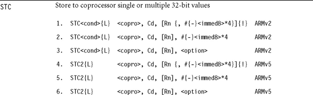
These instructions initiate a memory write, transferring data to memory from the given coprocessor. <copro> is the number of the coprocessor in the range p0 to p15. The core takes an undefined instruction trap if the coprocessor is not present. The memory write consists of a sequence of words to sequentially increasing addresses. The initial address is specified by the addressing mode in Table A.10. The coprocessor controls the number of words transferred, up to a maximum limit of 16 words. The fields {L} and Cd are interpreted by the coprocessor and ignored by the ARM. Typically Cd specifies the source coprocessor register for the transfer. The <option> field is an eight-bit integer enclosed in {}. Its interpretation is coprocessor dependent.
Table A.10
| Addressing format | Address accessed | Value written back to Rn |
| [Rn {,#{-}<immed>}] | Rn + {{-}<immed>} | Rn preserved |
| [Rn {,#{-}<immed>}]! | Rn + {{-}<immed>} | Rn + {{-}<immed>} |
| [Rn], #{-}<immed> | Rn | Rn + {-}<immed> |
| [Rn], <option> | Rn | Rn preserved |
If the address is not a multiple of four, then the access is unaligned. The restrictions on an unaligned access are the same as for STM.
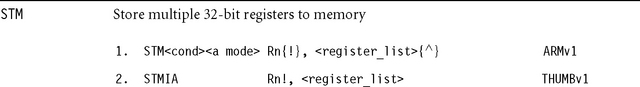
These instructions store multiple words to sequential memory addresses. The <register_list> specifies a list of registers to store, enclosed in curly brackets {}. Although theassembler allows you to specify the registers in the list in any order, the order is not stored in the instruction, so it is good practice to write the list in increasing order of register number since this is the usual order of the memory transfer.
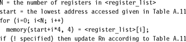
The following pseudocode shows the normal action of STM.Weuse <register_list>[i] to denote the register appearing at position i in the list starting at 0 for the first register. This assumes that the list is in order of increasing register number.
Note that memory(a, 4) refers to the four bytes at address a packed according to the current processor data endianness. If a is not a multiple of four, then the store is unaligned. Because the behavior of an unaligned store depends on the architecture revision, memory system, and system coprocessor (CP15) configuration, it is best to avoid unaligned stores if possible. Assuming that the external memory system does not abort unaligned stores, then the following rules usually apply:
![]() If the core has a system coprocessor and bit 1 (?-bit) or bit 22 (U-bit) of CP15:c1:c0:0 is set, then unaligned store-multiples cause an alignment fault data abort exception.
If the core has a system coprocessor and bit 1 (?-bit) or bit 22 (U-bit) of CP15:c1:c0:0 is set, then unaligned store-multiples cause an alignment fault data abort exception.
Table A.11 lists the possible addressing modes specified by <amode>. If you specify the !, then the base address register is updated according to Table A.11; otherwise, it is preserved. Note that the lowest register number is always written to the lowest address.
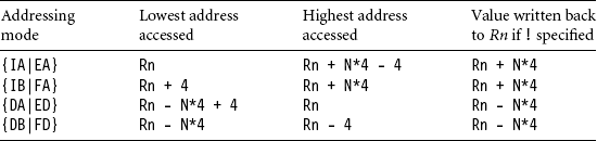
The first half of the addressing mode mnemonics stands for Increment After, Increment Before, Decrement After, and Decrement Before, respectively. Increment modes store the registers sequentially forward starting from address Rn (increment after) or Rn + 4 (increment before). Decrement modes have the same effect as if you stored the register list backwards to sequentially descending memory addresses starting from address Rn (decrement after) or Rn – 4 (decrement before).
The second half of the addressing mode mnemonics stands for the stack type you can implement with that address mode: Full Descending, Empty Descending, Full Ascending, and Empty Ascending. With a full stack, Rn points to the last stacked value. With an empty stack, Rn points to the first unused stack location. ARM stacks are usually full descending. You should use full descending or empty ascending stacks by preference, since STC also supports these addressing modes.
![]() For Thumb (format 2), Rn and the register list registers must be in the range r0 to r7.
For Thumb (format 2), Rn and the register list registers must be in the range r0 to r7.
![]() The number of registers N in the list must be nonzero.
The number of registers N in the list must be nonzero.
![]() If Rn appears in the register list and ! (writeback) is specified, the behavior is as follows: If Rn is the lowest register number in the list, then the original value is stored; otherwise, the stored value is unpredictable.
If Rn appears in the register list and ! (writeback) is specified, the behavior is as follows: If Rn is the lowest register number in the list, then the original value is stored; otherwise, the stored value is unpredictable.
![]() If pc appears in the register list, then the value stored is implementation defined.
If pc appears in the register list, then the value stored is implementation defined.
![]() If ^ is specified, then the operation is modified. The processor must not be in user or system mode. The registers appearing in the register list refer to the user mode versions of the registers and writeback must not be specified.
If ^ is specified, then the operation is modified. The processor must not be in user or system mode. The registers appearing in the register list refer to the user mode versions of the registers and writeback must not be specified.
![]() The time order of the memory accesses may depend on the implementation. Be careful when using a store multiple to access I/O locations where the access order matters. If the order matters, then check that the memory locations are marked as I/O in the page tables. Do not cross page boundaries, and do not use pc in the register list.
The time order of the memory accesses may depend on the implementation. Be careful when using a store multiple to access I/O locations where the access order matters. If the order matters, then check that the memory locations are marked as I/O in the page tables. Do not cross page boundaries, and do not use pc in the register list.
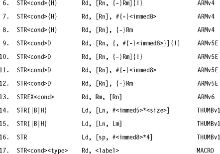
Formats 1 to 16 store a single data item of the type specified by the opcode suffix, using a preindexed or postindexed addressing mode. Tables A.12 and A.13 show the different addressing modes and data types.
Table A.12
| Addressing format | Address a accessed | Value written back to Rn |
| [Rn {,#{-}<immed>}] | Rn + {{-}<immed>} | Rn preserved |
| [Rn {,#{-}<immed>}]! | Rn + {{-}<immed>} | Rn + {{-}<immed>} |
| [Rn, {-}Rm {,<shift>}] | Rn + {-}<shifted_Rm> | Rn preserved |
| [Rn, {-}Rm {,<shift>}]! | Rn + {-}<shifted_Rm> | Rn + {-}<shifted_Rm> |
| [Rn], #{-}<immed> | Rn | Rn + {-}<immed> |
| [Rn], {-}Rm {,<shift>} | Rn | Rn + {-}<shifted_Rm> |

In Table A.13, memory(a, n) refers to n sequential bytes at address a. The bytes are packed according to the configured processor data endianness. memoryT(a, n) performs the access with user mode privileges, regardless of the current processor mode. The act of function IsExclusive(a) used by STREX depends on address a. If a has the shared TLB attribute, then IsExclusive(a) is true if address a is marked as exclusive for this processor. It then clears any exclusive accesses on this processor and any exclusive accesses to address a on other processors in the system. If a does not have the shared TLB attribute, then IsExclusive(a) is true if there is an outstanding exclusive access on this processor. It then clears any such outstanding access.
If the address a is not a multiple of <size>, then the store is unaligned. Because the behavior of an unaligned store depends on the architecture revision, memory system, and system coprocessor (CP15) configuration, it is best to avoid unaligned stores if possible. Assuming that the external memory system does not abort unaligned stores, then the following rules usually apply. In the rules, A is bit 1 of system coprocessor register CP15:c1:c0:0, and U is bit 22 of CP15:c1:c0:0, introduced in ARMv6. If there is no system coprocessor, then A = U = 0.
![]() If A = 1, then unaligned stores cause an alignment fault data abort exception except that word-aligned double-word stores are supported if U = 1.
If A = 1, then unaligned stores cause an alignment fault data abort exception except that word-aligned double-word stores are supported if U = 1.
![]() If A = 0 and U = 1, then unaligned stores are supported for STR{|T|H|SH}. Word-aligned stores are supported for STRD. A non-word-aligned STRD generates an alignment fault data abort.
If A = 0 and U = 1, then unaligned stores are supported for STR{|T|H|SH}. Word-aligned stores are supported for STRD. A non-word-aligned STRD generates an alignment fault data abort.
![]() If A = 0 and U = 0, then STR and STRT write to memory(a & ∼3, 4). All other unaligned operations are unpredictable but do not cause an alignment fault.
If A = 0 and U = 0, then STR and STRT write to memory(a & ∼3, 4). All other unaligned operations are unpredictable but do not cause an alignment fault.
Format 17 generates a pc -relative store accessing the address specified by <label>. In other words it assembles to STR<cond><type> Rd, [pc, #<offset>] whenever this instruction is supported and <offset>=<label>-pc is in range.
![]() For double-word stores (formats 9 to 12), Rd must be even and in the range r0 to r12.
For double-word stores (formats 9 to 12), Rd must be even and in the range r0 to r12.
![]() If the addressing mode updates Rn, then Rd and Rn must be distinct.
If the addressing mode updates Rn, then Rd and Rn must be distinct.
![]() If Rd is pc, then <size> must be 4. The value stored is implementation defined.
If Rd is pc, then <size> must be 4. The value stored is implementation defined.
![]() If Rn is pc, then the addressing mode must not update Rn. The value used for Rn is the address of the instruction plus eight bytes.
If Rn is pc, then the addressing mode must not update Rn. The value used for Rn is the address of the instruction plus eight bytes.
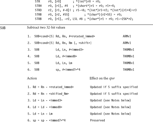
![]() If the operation updates the cpsr and Rd is not pc, then N = <Negative>, Z = <Zero>, C = <NoUnsignedOverflow>, and V = <SignedOverflow>. The carry flag is set this way because the subtract x – y is implemented as the add x + ∼y + 1. The carry flag is one if x + ∼y + 1 overflows. This happens when x ≥ y, when x – y doesn’t overflow.
If the operation updates the cpsr and Rd is not pc, then N = <Negative>, Z = <Zero>, C = <NoUnsignedOverflow>, and V = <SignedOverflow>. The carry flag is set this way because the subtract x – y is implemented as the add x + ∼y + 1. The carry flag is one if x + ∼y + 1 overflows. This happens when x ≥ y, when x – y doesn’t overflow.
![]() If Rd is pc, then the instruction effects a jump to the calculated address. If the operation updates the cpsr, then the processor mode must have an spsr; in this case, the cpsr is set to the value of the spsr.
If Rd is pc, then the instruction effects a jump to the calculated address. If the operation updates the cpsr, then the processor mode must have an spsr; in this case, the cpsr is set to the value of the spsr.
![]() If Rn or Rm is pc, then the value used is the address of the instruction plus eight bytes.
If Rn or Rm is pc, then the value used is the address of the instruction plus eight bytes.
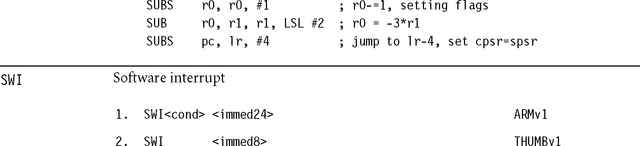
The SWI instruction causes the ARM to enter supervisor mode and start executing from the SWI vector. The return address and cpsr are saved in lr_svc and spsr_svc, respectively. The processor switches to ARM state and IRQ interrupts are disabled. The SWI vector is at address 0×00000008, unless high vectors are configured; then it is at address 0×FFFF0008.
The immediate operand is ignored by the ARM. It is normally used by the SWI exception handler as an argument determining which function to perform.
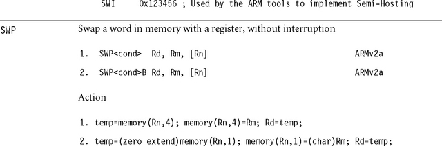
![]() The operations are atomic. They cannot be interrupted partway through.
The operations are atomic. They cannot be interrupted partway through.
![]() Rn and Rm must be different registers. Rn and Rd must be different registers.
Rn and Rm must be different registers. Rn and Rd must be different registers.
![]() Rn should be aligned to the size of the memory transfer.
Rn should be aligned to the size of the memory transfer.
![]() If a data abort occurs on the load, then the store does not occur. If a data abort occurs on the store, then Rd is not written.
If a data abort occurs on the load, then the store does not occur. If a data abort occurs on the store, then Rd is not written.
You can use the SWP instruction to implement 8-bit or 32-bit semaphores on ARMv5 and below. For ARMv6 use LDREX and STREX in preference. As an example, suppose a byte semaphore register pointed to by r1 can have the value 0xFF (claimed) or 0x00 (free). The following example claims the lock. If the lock is already claimed, then the code loops, waiting for an interrupt or task switch that will free the lock.
![]() If you specify the S prefix, then extend(x) sign extends x.
If you specify the S prefix, then extend(x) sign extends x.
![]() The cpsr is updated: N = <Negative>, Z = <Zero>, C = <shifter_C> (see Table A.3).
The cpsr is updated: N = <Negative>, Z = <Zero>, C = <shifter_C> (see Table A.3).
![]() If Rn or Rm is pc, then the value used is the address of the instruction plus eight bytes.
If Rn or Rm is pc, then the value used is the address of the instruction plus eight bytes.
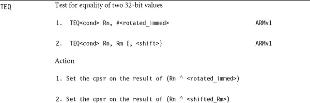
![]() Use this instruction instead of CMP when you want to check for equality and preserve the carry flag.
Use this instruction instead of CMP when you want to check for equality and preserve the carry flag.

![]() The cpsr is updated: N = <Negative>, Z = <Zero>, C = <shifter_C> (see Table A.3).
The cpsr is updated: N = <Negative>, Z = <Zero>, C = <shifter_C> (see Table A.3).
![]() If Rn or Rm is pc, then the value used is the address of the instruction plus eight bytes.
If Rn or Rm is pc, then the value used is the address of the instruction plus eight bytes.
![]() Use this instruction to test whether a selected set of bits are all zero.
Use this instruction to test whether a selected set of bits are all zero.

![]() RdHi and RdLo must be different registers.
RdHi and RdLo must be different registers.
![]() RdHi, RdLo, Rm, Rs must not be pc.
RdHi, RdLo, Rm, Rs must not be pc.
![]() This operation cannot overflow because (232 – 1)(232 – 1) + (232 – 1) + (232 – 1) = (264 – 1). You can use it to synthesize the multiword multiplications used by public key cryptosystems.
This operation cannot overflow because (232 – 1)(232 – 1) + (232 – 1) + (232 – 1) = (264 – 1). You can use it to synthesize the multiword multiplications used by public key cryptosystems.
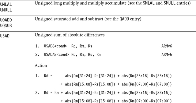
![]() abs(x) returns the absolute value of x. Rm and Rs are treated as unsigned.
abs(x) returns the absolute value of x. Rm and Rs are treated as unsigned.
![]() Rd, Rm, and Rs must not be pc.
Rd, Rm, and Rs must not be pc.
![]() The sum of absolute differences operation is common in video codecs where it provides a metric to measure how similar two images are.
The sum of absolute differences operation is common in video codecs where it provides a metric to measure how similar two images are.
A.4 ARM ASSEMBLER QUICK REFERENCE
This section summarizes the more useful commands and expressions available with the ARM assembler, armasm. Each assembly line has one of the following formats:

![]() <instruction> is any ARM or Thumb instruction supported by the processor you are assembling for. See Section A.3.
<instruction> is any ARM or Thumb instruction supported by the processor you are assembling for. See Section A.3.
![]() <label> is the name of a symbol to store the address of the instruction.
<label> is the name of a symbol to store the address of the instruction.
![]() <directive> is an ARM assembler directive. See Section A.4.4.
<directive> is an ARM assembler directive. See Section A.4.4.
![]() <symbol> is the name of a symbol used by the <directive>.
<symbol> is the name of a symbol used by the <directive>.
![]() <macro> is the name of a new directive defined using the MACRO directive.
<macro> is the name of a new directive defined using the MACRO directive.
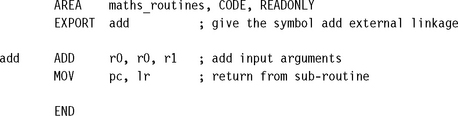
You must use an AREA directive to define an area before any ARM or Thumb instructions appear. All assembly files must finish with the END directive. The following example shows a simple assembly file defining a function add that returns the sum of the two input arguments:
A.4.1 ARM Assembler Variables
The ARM assembler supports three types of assemble time variables (see Table A.14). Variable names are case sensitive and must be declared before use with the directives GBLx or LCLx.
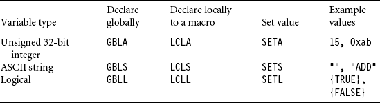
You can use variables in expressions (see Section A.4.2), or substitute their value at assembly time using the § operator. Specifically, $name. expands to the value of the variable name before the line is assembled. You can omit the final period if name is not followed by an alphanumeric or underscore. Use $$ to produce a single $. Arithmetic variables expand to an eight-digit hexadecimal string on substitution. Logical variables expand to T or F.
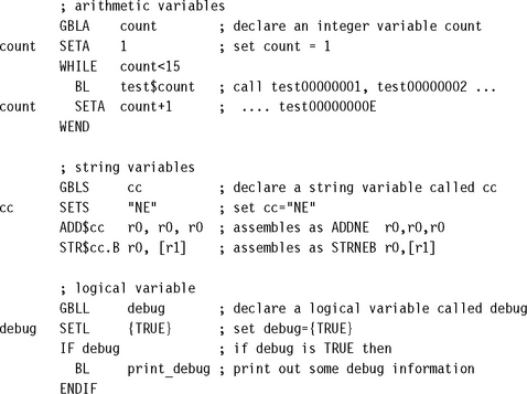
The following example code shows how to declare and substitute variables of each type:
A.4.2 ARM Assembler Labels
A label definition must begin on the first character of a line. The assembler treats indented text as an instruction, directive, or macro. It treats labels of the form <N><name> as a local label, where <N> is an integer in the range 0 to 99 and <name> is an optional textual name. Local labels are limited in scope by the ROUT directive. To reference a local label, you refer to it as %{|F|B}{|A|T}<N>{<name>}. The extra prefix letters tell the assembler how to search for the label:
![]() If you specify F, the assembler searches forward; if B, then the assembler searches backwards. Otherwise the assembler searches backwards and then forwards.
If you specify F, the assembler searches forward; if B, then the assembler searches backwards. Otherwise the assembler searches backwards and then forwards.
![]() If you specify T, the assembler searches the current macro only; if A, then the assembler searches all macro levels. Otherwise the assembler searches the current and higher macro nesting levels.
If you specify T, the assembler searches the current macro only; if A, then the assembler searches all macro levels. Otherwise the assembler searches the current and higher macro nesting levels.
A.4.3 ARM ASSEMBLER EXPRESSIONS
The ARM assembler can evaluate a number of numeric, string, and logical expressions at assembly time. Table A.15 shows some of the unary and binary operators you can use within expressions. Brackets can be used to change the order of evaluation in the usual way.
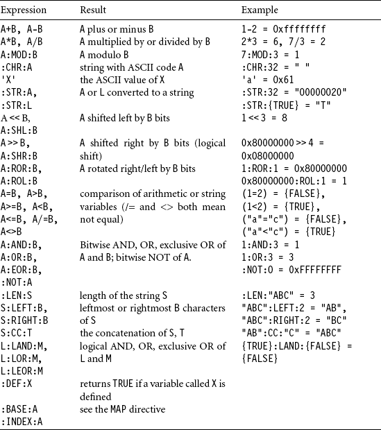
In Table A.15, A and B represent arbitrary integers; S and T, strings; and L and M, logical values. You can use labels and other symbols in place of integers in many expressions.
A.4.3.1 Predefined Variables
Table A.16 shows a number of special variables that can appear in expressions. These are predefined by the assembler, and you cannot override them.
Table A.16
| Variable | Value |
| {ARCHITECURE} | The ARM architecture of the CPU (“4T” for ARMv4T) |
| {ARMASM_VERSION} | The assembler version number |
| {CONFIG} or | The bit width of the instructions being assembled (32 for |
| {CODESIZE} | ARM state, 16 for Thumb state) |
| {CPU} | The name of the CPU being assembled for |
| {ENDIAN} | The configured endianness, “big” or “little” |
| {INTER} | {TRUE} if ARM/Thumb interworking is on |
| {PC} (alias.) | The address of the current instruction being assembled |
| {ROPI}, {RWPI} | {TRUE} if read-only/read-write position independent |
| {VAR} (alias @) | The MAP counter (see the MAP directive) |
A.4.4 ARM Assembler Directives
Here is an alphabetical list of the more common armasm directives.
ALIGN
![]()
Aligns the address of the next instruction to the form q*<expression>+<offset>. The alignment is relative to the start of the ELF section so this must be aligned appropriately (see the AREA directive). <expression> must be a power of two; the default is 4. <offset> is zero if not specified.
AREA
![]()
Starts a new code or data section of name <section>. Table A.17 lists the possible attributes.
Table A.17
| Attribute | Meaning |
| ALIGN=<expression> | Align the ELF section to a 2expression byte boundary. |
| ASSOC=<sectionname> | If this section is linked, also link <sectionname>. |
| CODE | The section contains instructions and is read only. |
| DATA | The section contains data and is read write. |
| NOINIT | The data section does not require initialization. |
| READONLY | The section is read only. |
| READWRITE | The section is read write. |
ASSERT
![]()
Assemble time assert. If the logical expression is false, then assembly terminates with an error.
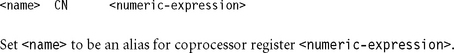
CODE16, CODE32
CODE16 tells the assembler to assemble the following instructions as 16-bit Thumb instructions. CODE32 indicates 32-bit ARM instructions (the default for armasm).
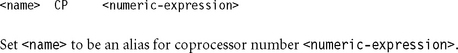
DATA
![]()
The DATA directive indicates that the label points to data rather than code. In Thumb mode this prevents the linker from setting the bottom bit of the label. Bit 0 of a function pointer or code label is 0 for ARM code and 1 for Thumb code (see the BX instruction).
DCB, DCD{U}, DCI, DCQ{U}, DCW{U}
These directives allocate one or more bytes of initialized memory according to Table A.18. Follow each directive with a comma-separated list of initialization values. If you specify the optional U suffix, then the assembler does not insert any alignment padding.
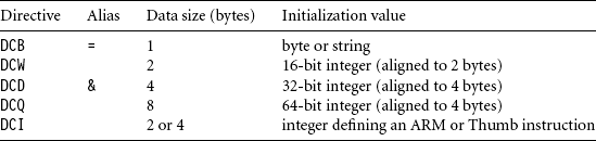
![]()
END
This directive must appear at the end of a source file. Assembler source after an END directive is ignored.
ENTRY
This directive specifies the program entry point for the linker. The entry point is usually contained in the ARM C library.
EQU (alias *)
![]()
This directive is similar to #define in C. It defines a symbol <name> with value defined by the expression. This value cannot be redefined. See Section A.4.1 for the use of redefinable variables.
EXPORT (alias GLOBAL)
![]()
Assembler symbols are local to the object file unless exported using this command. You can link exported symbols with other object and library files. The optional [WEAK] suffix indicates that the linker should try and resolve references with other instances of this symbol before using this instance.
EXTERN, IMPORT
![]()
Both of these directives declare the name of an external symbol, defined in another object file or library. If you use this symbol, then the linker will resolve it at link time. For IMPORT, the symbol will be resolved even if you don’t use it. For EXTERN, only used symbols are resolved. If you declare the symbol as [WEAK], then no error is generated if the linker cannot resolve the symbol; instead the symbol takes the value 0.
FUNCTION (alias PROC) and ENDFUNC (alias ENDP)
The FUNCTION and ENDFUNC directives mark the start and end of an ATPCS-compliant function. Their main use is to improve the debug view and allow backtracking of function calls during debugging. They also allow the profiler to more accurately profile assembly functions. You must precede the function directive with the ATPCS function name. For example:
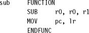
GBLA, GBLL, GBLS
Directives defining global arithmetic, logic, and string variables, respectively. See Section A.4.1.
IF (alias [), ELSE (alias |), ENDIF (alias])
These directives provide for conditional assembly. They are similar to #if, #else, #endif, available in C. The IF directive is followed by a logical expression. The ELSE directive may be omitted. For example:
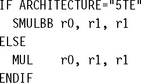
INCBIN
![]()
This directive includes the raw data contained in the binary file <filename> at the current point in the assembly. For example, INCBIN table.dat.
INCLUDE (alias GET)
Use this directive to include another assembly file. It is similar to the #include command in C. For example, INCLUDE header.h.
INFO (alias !)
![]()
If<numeric_expresssion> is nonzero, then assembly terminates with error <string_expresssion>. Otherwise the assembler prints <string_expression> as an information message.
KEEP
![]()
By default the assembler does not include local symbols in the object file, only exported symbols (see EXPORT). Use KEEP to include all local symbols or a specified local symbol.
LCLA, LCLL, LCLS
These directives declare macro-local arithmetic, logical, and string variables, respectively.
See Section A.4.1.
LTORG
Use LTORG to insert a literal pool. The assembler uses literal pools to store the constants appearing in the LDR Rd,=<value> instruction. See LDR format 19. Usually the assembler inserts literal pools automatically, at the end of each area. However, if an area is too large, then the LDR instruction cannot reach this literal pool using pc-relative addressing. Then you need to insert a literal pool manually, near the LDR instruction.
MACRO, MEXIT, MEND
Use these directives to declare a new assembler macro or pseudoinstruction. The syntax is
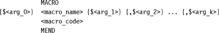
The macro parameters are stored in the dummy variables $<arg_i>. This argument is set to the empty string if you don’t supply a parameter when calling the macro. The MEXIT directive terminates the macro early and is usually used inside IF statements. For example, the following macro defines a new pseudoinstruction SMUL, which evaluates to a SMULBB on an ARMv5TE processor, and an MUL otherwise.
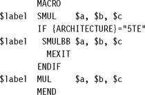
MAP (alias  ), FIELD (alias #)
These directives define objects similar to C structures. MAP sets the base address or offset of a structure, and FIELD defines structure elements. The syntax is
![]()
The MAP directive sets the value of the special assembler variable {VAR} to the base address of the structure. This is either the value <base> or the register relative value <base_register>+<base>. Each FIELD directive sets <name> to the value VAR and increments VAR by the specified number of bytes. For register relative values, the expressions :INDEX:<name> and :BASE:<name> return the element offset from base register, and base register number, respectively.
In practice the base register form is not that useful. Instead you can use the plain form and mention the base register explicitly in the instruction. This allows you to point to a structure of the same type with different base registers. The following example sets up a structure on the stack of two int variables:
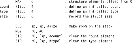
NOFP
This directive bans the use of floating-point instructions in the assembly file. We don’t cover floating-point instructions and directives in this appendix.
OPT
The OPT directive controls the formatting of the armasm -list option. This is seldom used now that source-level debugging is available. See the armasm documentation.
RLIST, RN
![]()
These directives name a list of ARM registers or a single ARM register. For example, the following code names r0 as arg and the ATPCS preserved registers as saved.
![]()
SETA, SETL, SETS
These directives set the values of arithmetic, logical, and string variables, respectively. See Section A.4.1.
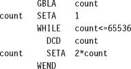
A.5 GNU ASSEMBLER QUICK REFERENCE
This section summarizes the more useful commands and expressions available with the GNU assembler, gas, when you target this assembler for ARM. Each assembly line has the format
![]()
Unlike the ARM assembler, you needn’t indent instructions and directives. Labels are recognized by the following colon rather than their position at the start of the line. The following example shows a simple assembly file defining a function add that returns the sum of the two input arguments:

A.5.1 GNU Assembler Directives
Here is an alphabetical list of the more common gas directives.
![]()
Inserts the string as data into the assembly, as for DCB in armasm.
![]()
As for .ascii but follows the string with a zero byte.
![]()
Aligns the address to <power_of_2> bytes. The assembler aligns by adding bytes of value <fill_value> or a suitable default. The alignment will not occur if more than <max_padding> fill bytes are required. Similar to ALIGN in armasm.
![]()
Inserts a list of byte values as data into the assembly, as for DCB in armasm.
![]()
Sets the instruction width in bits. Use 16 for Thumb and 32 for ARM assembly. Similar to CODE16 and CODE32 in armasm.
![]()
Use with .if and .endif. Similar to ELSE in armasm.
![]()
Marks the end of the assembly file. This is usually omitted.
![]()
Ends a conditional compilation code block. See .if, .ifdef, .ifndef, Similar to ENDIF in armasm.
![]()
Ends a macro definition. See .macro. Similar to MEND in armasm.
![]()
Ends a repeat loop. See .rept and .irp. Similar to WEND in armasm.
![]()
This directive sets the value of a symbol. It is similar to EQU in armasm.
![]()
Causes assembly to halt with an error.
![]()
Exit a macro partway through. See .macro. Similar to MEXIT in armasm.
![]()
This directive gives the symbol external linkage. It is similar to EXPORT in armasm.
![]()
Inserts a list of 16-bit values as data into the assembly, as for DCW in armasm.
![]()
Makes a block of code conditional. End the block using .endif. Similar to IF in armasm. See also .else.
![]()
Include a block of code if <symbol> is defined. End the block with .endif.
![]()
Include a block of code if <symbol> is not defined. End the block with .endif.
![]()
Includes the indicated source file. Similar to INCLUDE in armasm or #include in C.
![]()
Repeats a block of code, once for each value in the value list. Mark the end of the block using a .endr directive. In the repeated code block, use <param> to substitute the associated value in the value list.
![]()
Defines an assembler macro called <name> with k parameters. The macro definition must end with .endm. To escape from the macro at an earlier point, use .exitm. These directives are similar to MACRO, MEND, and MEXIT in armasm. You must precede the dummy macro parameters by . For example:
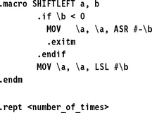
Repeats a block of code the given number of times. End the block with .endr.
![]()
This directive names a register. It is similar to the RN directive in armasm except that you must supply a name rather than a number on the right. For example, acc .req r0.
![]()
Starts a new code or data section. Usually you should call a code section .text, an initialized data section .data, and an uninitialized data section .bss. These have default flags, and the linker understands these default names. The directive is similar to the armasm directive AREA. Table A.19 lists possible characters to appear in the <flags> string for ELF format files.
Table A.19
.section flags for ELF format files.
| Flag | Meaning |
| a | allocatable section |
| w | writable section |
| x | executable section |
![]()
This directive sets the value of a variable. It is similar to SETA in armasm.
![]()
Reserves the given number of bytes. The bytes are filled with zero or <fill_byte> if specified. It is similar to SPACE in armasm.
![]()
Inserts a list of 32-bit word values as data into the assembly, as for DCD in armasm.