
FIRMWARE
This chapter discusses firmware for ARM-based embedded systems. Firmware is an important part of any embedded system since it is frequently the first code to be ported and executed on a new platform. Firmware can vary from being a complete software embedded system to just a simple initialization and bootloader routine. We have divided this chapter into two sections.
The first section introduces firmware. In this section we define the term firmware and describe two popular industry standard firmware packages available for the ARM processor—ARM Firmware Suite and Red Hat’s RedBoot. These firmware packages are general purpose and can be ported to different ARM platforms relatively easily and quickly.
The second section focuses on just the initialization and bootloader process. To help with this, we have developed a simple example called Sandstone. Sandstone is designed to initialize hardware, load an image into memory, and relinquish control of the pc over to that image.
We start by first discussing firmware and introduce the two common ARM firmware packages.
10.1 FIRMWARE AND BOOTLOADER
We realize that the use of terms may differ among engineers, but we will use the following definitions:
![]() The firmware is the deeply embedded, low-level software that provides an interface between the hardware and the application/operating system level software. It resides in the ROM and executes when power is applied to the embedded hardware system. Firmware can remain active after system initialization and supports basic system operations. The choice of which firmware to use for a particular ARM-based system depends upon the specific application, which can range from loading and executing a sophisticated operating system to simply relinquishing control to a small microkernel. Consequently, requirements can vary greatly from one firmware implementation to another. For example, a small system may require just minimal firmware support to boot a small operating system. One of the main purposes of firmware is to provide a stable mechanism to load and boot an operating system.
The firmware is the deeply embedded, low-level software that provides an interface between the hardware and the application/operating system level software. It resides in the ROM and executes when power is applied to the embedded hardware system. Firmware can remain active after system initialization and supports basic system operations. The choice of which firmware to use for a particular ARM-based system depends upon the specific application, which can range from loading and executing a sophisticated operating system to simply relinquishing control to a small microkernel. Consequently, requirements can vary greatly from one firmware implementation to another. For example, a small system may require just minimal firmware support to boot a small operating system. One of the main purposes of firmware is to provide a stable mechanism to load and boot an operating system.
![]() The bootloader is a small application that installs the operating system or application onto a hardware target. The bootloader only exists up to the point that the operating system or application is executing, and it is commonly incorporated into the firmware.
The bootloader is a small application that installs the operating system or application onto a hardware target. The bootloader only exists up to the point that the operating system or application is executing, and it is commonly incorporated into the firmware.
To help understand the features of different firmware implementations, we have a common execution flow (see Table 10.1). Each stage is now discussed in more detail.
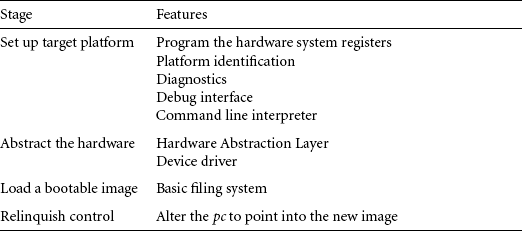
The first stage is to set up the target platform—in other words, prepare the environment to boot an operating system since an operating system expects a particular type of environment before it can operate. This step involves making sure that the platform is correctly initialized (for example, making sure that the control registers of a particular microcontroller are placed at a known address or changing the memory map to an expected layout).
It is common for the same executable to operate on different cores and platforms. In this case, the firmware has to identify and discover the exact core and platform it is operating on. The core is normally recognized by reading register 0 in coprocessor 15, which holds both the processor type and the manufacturer name. There are multiple ways to identify the platform, from checking for the existence of a set of particular peripherals to simply reading a preprogrammed chip.
Diagnostics software provides a useful way for quickly identifying basic hardware malfunctions. Because of the nature of this type of software, it tends to be specific to a particular piece of hardware.
Debug capabiliy is provided in the form of a module or monitor that provides software assistance for debugging code running on a hardware target. This assistance includes the following:
![]() Setting up breakpoints in RAM. A breakpoint allows a program to be interrupted and the state of the processor core to be examined.
Setting up breakpoints in RAM. A breakpoint allows a program to be interrupted and the state of the processor core to be examined.
![]() Listing and modifying memory (using peek and poke operations).
Listing and modifying memory (using peek and poke operations).
![]() Showing current processor register contents.
Showing current processor register contents.
![]() Disassembling memory into ARM and Thumb instruction mnemonics.
Disassembling memory into ARM and Thumb instruction mnemonics.
These are interactive functions: you can either send the commands through a command line interpreter (CLI) or through a dedicated host debugger attached to the target platform. Unless the firmware has access to the internal hardware debug circuitry, only RAM images can be debugged through a software debug mechanism.
The CLI is commonly available on the more advanced firmware implementations. It allows you to change the operating system to be booted by altering the default configurations through typing commands at a command prompt. For embedded systems, the CLI is commonly controlled through a host terminal application. Communication between the host and the target is normally over a serial or network connection.
The second stage is to abstract the hardware. The Hardware Abstraction Layer (HAL) is a software layer that hides the underlying hardware by providing a set of defined programming interfaces. When you move to a new target platform, these programming interfaces remain constant but the underlying implementation changes. For instance, two target platforms might use a different timer peripheral. Each peripheral would require new code to initialize and configure the device. The HAL programming interface would remain unaltered even though both the hardware and software may differ greatly between implementations.
The HAL software that communicates with specific hardware peripherals is called a device driver. A device driver provides a standard application programming interface (API) to read and write to a specific peripheral.
The third stage is to load a bootable image. The ability of firmware to carry out this activity depends upon the type of media used to store the image. Note that not all operating system images or application images need to be copied into RAM. The operating system image or application image can simply execute directly from ROM.
ARM processors are normally found in small devices that include flash ROM. A common feature is a simple flash ROM filing system (FFS), which allows multiple executable images to be stored.
Other media devices, such as hard drives, require that the firmware incorporates a device driver that is suitable for accessing the hardware. Accessing the hardware requires that the firmware has knowledge of the underlying filing system format, which gives the firmware the ability to read the filing system, find the file that contains the image, and copy the image into memory. Similarly, if the image is on the network, then the firmware must also understand the network protocol as well as the Ethernet hardware.
The load process has to take into account the image format. The most basic image format is plain binary. A plain binary image does not contain any header or debug information. A popular image format for ARM-based systems is Executable and Linking Format (ELF). This format was originally developed for UNIX systems and replaced the older format called Common Object File Format (COFF). ELF files come in three forms: relocatable, executable, and shared object.
Most firmware systems must deal with the executable form. Loading an ELF image involves deciphering the standard ELF header information (that is, execution address, type, size, and so on). The image may also be encrypted or compressed, in which case the load process would involve performing decryption or decompression on the image.
The fourth stage is to relinquish control. This is where the firmware hands over control of the platform to an operating system or application. Note that not all firmware hands over control; instead the firmware can remain the controlling software on the platform.
Firmware designed to pass control to an operating system may become inactive once the operating system has control. Alternatively, the Machine Independent Layer (MIL) or Hardware Abstraction Layer (HAL) part of the firmware can remain active. This layer exposes, through the SWI mechanism, a standard application interface for specific hardware devices.
Relinquishing control on an ARM system means updating the vector table and modifying the pc. Updating the vector table involves modifying particular exception and interrupt vectors so that they point to specialized operating system handlers. The pc has to be modified so that it points to the operating system entry point address.
For more sophisticated operating systems, such as Linux, relinquishing control requires that a standard data structure be passed to the kernel. This data structure explains the environment that the kernel will be running in. For example, one field may include the amount of available RAM on the platform, while another field includes the type of MMU being used.
We use these definitions to describe two common firmware suites.
10.1.1 ARM FIRMWARE SUITE
ARM has developed a firmware package called the ARM Firmware Suite (AFS). AFS is designed purely for ARM-based embedded systems. It provides support for a number of boards and processors including the Intel XScale and StrongARM processors. The package includes two major pieces of technology, a Hardware Abstraction Layer called μHAL (pronounced micro-HAL) and a debug monitor called Angel.
μHAL provides a low-level device driver framework that allows it to operate over different communication devices (for example, USB, Ethernet, or serial). It also provides a standard API. Consequently, when a port takes place, the various hardware-specific parts must be implemented in accordance with the various μHAL API functions.
This has the advantage of making the porting process relatively straightforward since you have a standard function framework to work within. Once the firmware is ported, the task of moving an operating system over to the new target platform can take place. The speed of this activity depends upon whether the OS takes advantage of the ported μHAL API call to access the hardware.
μHAL supports these main features:
![]() System initialization—setting up the target platform and processor core. Depending upon the complexity of the target platform, this can either be a simple or complicated task.
System initialization—setting up the target platform and processor core. Depending upon the complexity of the target platform, this can either be a simple or complicated task.
![]() Polled serial driver—used to provide a basic method of communication with a host.
Polled serial driver—used to provide a basic method of communication with a host.
![]() LED support—allows control over the LEDs for simple user feedback. This provides an application the ability to display operational status.
LED support—allows control over the LEDs for simple user feedback. This provides an application the ability to display operational status.
![]() Timer support—allows a periodic interrupt to be set up. This is essential for preemptive context switching operating systems that require this mechanism.
Timer support—allows a periodic interrupt to be set up. This is essential for preemptive context switching operating systems that require this mechanism.
![]() Interrupt controllers—support for different interrupt controllers.
Interrupt controllers—support for different interrupt controllers.
The boot monitor in μHAL contains a CLI.
The second technology, Angel, allows communication between a host debugger and a target platform. It allows you to inspect and modify memory, download and execute images, set breakpoints, and display processor register contents. All this control is through the host debugger. The Angel debug monitor must have access to the SWI and IRQ or FIQ vectors.
Angel uses SWI instructions to provides a set of APIs that allow a program to open, read, and write to a host filing system. IRQ/FIQ interrupts are used for communication purposes with the host debugger.
10.1.2 RED HAT REDBOOT
RedBoot is a firmware tool developed by Red Hat. It is provided under an open source license with no royalties or up front fees. RedBoot is designed to execute on different CPUs (for instance, ARM, MIPS, SH, and so on). It provides both debug capability through GNU Debugger (GDB), as well as a bootloader. The RedBoot software core is based on a HAL.
RedBoot supports these main features:
![]() Communication—configuration is over serial or Ethernet. For serial, X-Modem protocol is used to communicate with the GNU Debugger (GDB). For Ethernet, TCP is used to communicate with GDB. RedBoot supports a range of network standards, such as bootp, telnet, and tftp.
Communication—configuration is over serial or Ethernet. For serial, X-Modem protocol is used to communicate with the GNU Debugger (GDB). For Ethernet, TCP is used to communicate with GDB. RedBoot supports a range of network standards, such as bootp, telnet, and tftp.
![]() Flash ROM memory management—provides a set of filing system routines that can download, update, and erase images in flash ROM. In addition, the images can either be compressed or uncompressed.
Flash ROM memory management—provides a set of filing system routines that can download, update, and erase images in flash ROM. In addition, the images can either be compressed or uncompressed.
![]() Full operating system support—supports the loading and booting of Embedded Linux, Red Hat eCos, and many other popular operating systems. For Embedded Linux, RedBoot supports the ability to define parameters that are passed directly to the kernel upon booting.
Full operating system support—supports the loading and booting of Embedded Linux, Red Hat eCos, and many other popular operating systems. For Embedded Linux, RedBoot supports the ability to define parameters that are passed directly to the kernel upon booting.
10.2 EXAMPLE: SANDSTONE
We have designed Sandstone to be a minimal system. It carries out only the following tasks: set up target platform environment, load a bootable image into memory, and relinquish control to an operating system. It is, however, still a real working example.
The implementation is specific to the ARM Evaluator-7T platform, which includes an ARM7TDMI processor. This example shows you exactly how a simple platform can be set up and a software payload can be loaded into memory and booted. The payload can either be an application or operating system image. Sandstone is a static design and cannot be configured after the build process is complete. Table 10.2 lists the basic characteristics of Sandstone.
Table 10.2
| Feature | Configuration |
| Code | ARM instructions only |
| Tool chain | ARM Developer Suite 1.2 |
| Image size | 700 bytes |
| Source | 17 KB |
| Memory | remapped |
We will walk you through the directory layout and code structure. The directory layout shows you where the source code is located and where the different build files are placed. The code structure focuses more on the actual initialization and boot process.
Note that Sandstone is written entirely in ARM assembler and is a working piece of code that can be used to intialize target hardware and boot any piece of software, within reason, on the ARM Evaluator-7T.
10.2.1 SANDSTONE DIRECTORY LAYOUT
Sandstone can be found on our Web site. If you take a look at Sandstone, you will see that the directory structure is as shown in Figure 10.1. The structure follows a standard style that we will continue to use in further chapters. The sandstone source file sand.s is located under the sand/build/src directory.
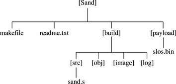
The object file produced by the assembler is placed under the build/obj directory. The object file is then linked, and the final Sandstone image is placed under the sand/build/image directory. This image includes both the Sandstone code and the payload. The payload image, the image that is loaded and booted by Sandstone, is found under the sand/payload directory.
For information about the Sandstone build procedure, take a look at the readme.txt file under the sand directory. This file contains a description of how to build the example binary image for the ARM Evaluator-7T.
10.2.2 SANDSTONE CODE STRUCTURE
Sandstone consists of a single assembly file. The file structure is broken down into a number of steps, where each step corresponds to a stage in the execution flow of Sandstone (see Table 10.3).
Table 10.3
| Step | Description |
| 1 | Take the Reset exception |
| 2 | Start initializing the hardware |
| 3 | Remap memory |
| 4 | Initialize communication hardware |
| 5 | Bootloader—copy payload and relinquish control |
We will take you through these steps, trying to avoid as much as possible the platform-specific parts. You should note that some specific parts are unavoidable (for example, configuring system registers and memory remapping).
The initial goal of Sandstone is to set up the target platform environment so that it can provide some form of feedback to indicate that the firmware is running and has control of the platform.
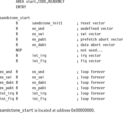
10.2.2.1 Step 1: Take the Reset Exception
Execution begins with a Reset exception. Only the reset vector entry is required in the default vector table. It is the very first instruction executed. You can see from the code here that all the vectors, apart from the reset vector, branch to a unique dummy handler—a branch instruction that causes an infinite loop. It is assumed that no exception or interrupt will occur during the operation of Sandstone. The reset vector is used to move the execution flow to the second stage.
10.2.2.2 Step 2: Start Initializing the Hardware
The primary phase in initializing hardware is setting up system registers. These registers have to be set up before accessing the hardware. For example, the ARM Evaluator-7T has a seven-segment display, which we have chosen to be used as a feedback tool to indicate that the firmware is active. Before we can set up the segment display, we have to position the base address of the system registers to a known location. In this case, we have picked the default address 0x03ff0000, since this places all the hardware system registers away from both ROM and RAM, separating the peripherals and memory.
Consequently, all the microcontroller memory-mapped registers are located as an offset from 0x03ff0000. This is achieved using the following code:
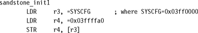
Register r3 contains the default system register base address and is used to set the new default address, as well as other specific attributes such as the cache. Register r4 contains the new configuration. The top 16 bits contain the high address of the new system register base address 0x03ff, and the lower 16 bits contain the new attribute settings 0xffa0.
After setting up the system register base address, the segment display can be configured. The segment display hardware is used to show Sandstone’s progress. Note that the segment display is not shown since it is hardware specific.
10.2.2.3 Step 3: Remap Memory
One of the major activities of hardware initialization is to set up the memory environment. Sandstone is designed to initialize SRAM and remap memory. This process occurs fairly early on in the initialization of the system. The platform starts in a known memory state, as shown in Table 10.4.
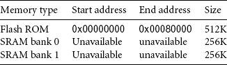
As you can see, when the platform is powered up, only flash ROM is assigned a location in the memory map. The two SRAM banks (0 and 1) have not been initialized and are not available. The next stage is to bring in the two SRAM banks and remap flash ROM to a new location. This is achieved using the following code:
![]()
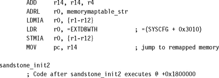
The first part of the code calculates the absolute address of the routine sandstone_init2 before remapping takes place. This address is used by Sandstone to jump to the next routine in the new remapped environment.
The second part carries out the memory remapping. The new memory map data is loaded into registers r1 to r12, from a structure pointed by memorymaptable_str. This structure, using the registers, is then written to the memory controller offset 0x3010 from system configuration register. Once this is complete, the new memory map as shown in Table 10.5 is active.
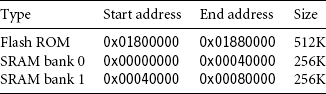
You can see that the SRAM banks are now available, and the flash ROM is set to a higher address. The final part is to jump to the next routine, or stage, of the firmware.
This jump is achieved by taking advantage of the ARM pipeline. Even though the new memory environment is active, the next instruction has already been loaded into the pipeline. The next routine can be called by moving the contents of register r14 (the address sandstone_init2) into the pc. We achieve this by using a single MOV instruction that follows immediately after the remap code.
The results of executing step 3 are the following:
![]() Memory has been remapped as shown in Table 10.5.
Memory has been remapped as shown in Table 10.5.
![]() pc now points to the next step. This address is located in the newly remapped flash ROM.
pc now points to the next step. This address is located in the newly remapped flash ROM.
10.2.2.4 Step 4: Initialize Communication Hardware
Communication initialization involves configuring a serial port and outputting a standard banner. The banner is used to show that the firmware is fully functional and memory has been successfully remapped. Again, because the code for initializing the serial port on the ARM Evaluator-7T is hardware specific, it is not shown.
The serial port is set to 9600 baud, no parity, one stop bit, and no flow control. If a serial cable is attached to the board, then the host terminal has to be configured with these settings.
The results of executing step 4 are the following:
10.2.2.5 Step 5: Bootloader—Copy Payload and Relinquish Control
The final stage involves copying a payload and relinquishing control of the pc over to the copied payload. This is achieved using the code shown here. The first part of the code sets up the registers r12, r13, and r14 used in the block copy. The bootloader code assumes that the payload is a plain binary image that requires no deciphering or uncompressing.
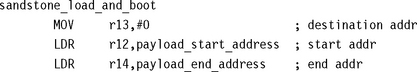
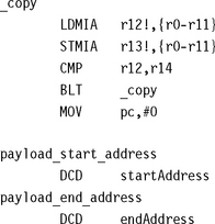
Destination register r13 points to the beginning of SRAM, in this case 0x00000000. The source register r12 points to the start of the payload, and the source end register r14 points to the end of the payload. Using these registers, the payload is then copied into SRAM.
Control of the pc is then relinquished to the payload by forcing the pc to the entry address of the copied payload. For this particular payload the entry point is address 0x00000000. The payload now has control of the system.
The results of executing step 5 are the following:
![]() Payload copied into SRAM, address 0x00000000.
Payload copied into SRAM, address 0x00000000.
![]() Control of the pc is relinquished to the payload; pc = 0x00000000.
Control of the pc is relinquished to the payload; pc = 0x00000000.
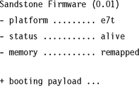
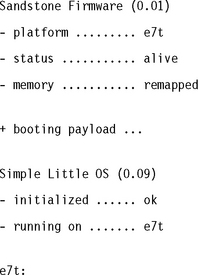
![]() The system is completely booted. The following output is shown on the serial port:
The system is completely booted. The following output is shown on the serial port:
10.3 SUMMARY
This chapter covered the firmware. We defined firmware as the low-level code that interfaces the hardware with an application or operating system. We also defined the bootloader as the software that loads an operating system or application into memory and relinquishes control of the pc to that software.
We introducted the ARM Firmware Suite and RedBoot. The ARM Firmware Suite is designed only for ARM-based systems. RedBoot, however, is more generic and can be used on other, non-ARM processors.
Next we looked at a firmware example called Sandstone. Sandstone initializes the hardware and then loads and boots an image following this procedure:
![]() Starts initializing the hardware; sets the system register’s base address and initializes segment display hardware.
Starts initializing the hardware; sets the system register’s base address and initializes segment display hardware.
![]() Remaps memory; ROM address = high addr and SRAM addr = 0x00000000.
Remaps memory; ROM address = high addr and SRAM addr = 0x00000000.
![]() Initializes the communication hardware output on the serial port.
Initializes the communication hardware output on the serial port.
![]() Bootloader—loads an image into SRAM and relinquishes control of the pc to the image (pc = 0x00000000).
Bootloader—loads an image into SRAM and relinquishes control of the pc to the image (pc = 0x00000000).