
Chapter 12. Configuring High Availability
This chapter covers the following topics:
- High Availability on NAC Appliance Manager
- High Availability on NAC Appliance Server
- Example of a High Availability Configuration for NAC Appliance Manager and Server
This chapter explains how NAC Appliance Manager and NAC Appliance Server work in a failover mode. You will learn how to configure high availability (HA) and what happens if one of the NAC Appliance Managers or NAC Appliance Servers fails.
High Availability on NAC Appliance Manager
NAC Appliance Manager is the brains behind the Cisco NAC Appliance solution. All configuration is done on NAC Appliance Manager, and it pushes the relevant configurations to all NAC Appliance Servers. NAC Appliance Manager essentially controls the NAC solution at your site. As a result, it is extremely important that you protect your NAC solution from a single point of failure.
NAC Appliance Manager can be configured in High Availability mode, which means there are two NAC Appliance Managers acting in an active-standby configuration. The entire configuration on NAC Appliance Manager is stored in a database. The standby NAC Appliance Manager synchronizes its database with the database on the active NAC Appliance Manager. Any changes made to the configuration on the active NAC Appliance Manager are immediately pushed to the standby NAC Appliance Manager.
The active and standby NAC Appliance Managers share a virtual IP; however, they don't share a virtual MAC. The active and standby NAC Appliance Managers exchange heartbeat packets every 2 seconds on User Datagram Protocol (UDP) port 694. These heartbeat packets can be sent in one of the following ways:
- Over a serial link
- Over the eth1 interface
- Over both the serial link and the eth1 interface
The standby NAC Appliance Manager monitors the heartbeat packets, and if the heartbeat timer expires, it determines that the active NAC Appliance Manager is no longer up and failover occurs. The standby NAC Appliance Manager moves to Active status, taking up the functioning of the active NAC Appliance Manager. The heartbeat timer, as of the 4.1 release, is set to 15 seconds by default and is not configurable. However, this timer will become a configurable option in one of the future releases to provide more flexibility to customers. If the heartbeat packets are sent over both the serial link and the eth1 interface, the heartbeat packets on both links have to fail for the failover to occur. If the standby NAC Appliance Manager detects missed heartbeats on the serial link while heartbeats on the eth1 interface are fine, no failover occurs. The same condition exists if heartbeats on the eth1 interface fail, but the serial link heartbeats are fine.
As you might have noticed by now, the heartbeat packet exchange mechanism protects you from a box failure or a failure of the eth1 interface link. However, it doesn't provide protection if the eth0 interface fails.
For protection against eth0 interface failure, NAC Appliance Manager has High Availability failover using link failure detection. On the active and standby NAC Appliance Managers, configure an IP address that is external to both NAC Appliance Managers and exists on the trusted part of the network. Both NAC Appliance Managers will ping this external IP address every 2 seconds using the eth0 interface. The status of the pings is exchanged between the two NAC Appliance Managers using the heartbeat packets. If the active NAC Appliance Manager detects that it hasn't received a response to three ping packets, it communicates a ping failed status to the standby NAC Appliance Manager using the heartbeat packets. If the standby NAC Appliance Manager has a successful ping status, it determines that there is a problem with the active NAC Appliance Manager's eth0 interface and failover occurs. If both the active and standby NAC Appliance Managers are unable to ping the external IP address, no failover occurs. To avoid a single point of failure, be sure to choose an external IP that is highly available. Hot Standby Router Protocol (HSRP) virtual addresses are good choices for this external IP selection.
Now that you know about the high availability options, your next question might be what the best method is to configure High Availability mode on NAC Appliance Manager. This depends on the topology of the network and where the NAC Appliance Managers are placed.
As an example, assume that you have a collapsed core/distribution layer with two switches configured with HSRP, and all the access switches are dual-homed to the core/distribution switches. Each NAC Appliance Manager is connected to one of the core switches. Make sure that NAC Appliance Manager fails over if any one of the following conditions arises:
- Active Manager fails
- eth0 link of active Manager fails
- Core 1 switch fails
The following is how you design a High Availability solution for NAC Appliance Manager in this situation:
- Use both the serial link and the eth1 interface for the heartbeat packets.
- Use eth0 link failure detection based failover.
- The external IP address to be used for the eth0 link failure detection will be the HSRP address on the core switch configured for the NAC Appliance Manager's management VLAN.
The active and standby NAC Appliance Managers will send Internet Control Message Protocol (ICMP) echo ping packets out of the eth0 interface to the core switch HSRP address. The status of these pings will be sent via the heartbeat packets on both the serial link and the eth1 link.
If the active NAC Appliance Manager fails, no heartbeat packets will be sent on either the serial or eth1 link. As a result, the standby NAC Appliance Manager transitions to Active status after the heartbeat timer expires.
If the eth0 link of the active NAC Appliance Manager fails, the active NAC Appliance Manager will communicate this ping failed status to the standby NAC Appliance Manager. The standby NAC Appliance Manager will check whether it is able to ping the external IP address. If it is successful, the standby NAC Appliance Manager will instruct the currently active NAC Appliance Manager to go into Standby status, and the former standby NAC Appliance Manager transitions to Active status.
If the Core 1 switch fails, the Core 2 switch becomes the HSRP active switch. Pings from the eth0 interface will fail, and the heartbeat over the eth1 link will also fail. The serial link will remain up, however. The eth0 ping failed status will be communicated to the standby NAC Appliance Manager. The standby NAC Appliance Manager will have a ping success status because it will be able to get a response to its ping packets from the core 2 switch. This causes the currently active NAC Appliance Manager to go into Standby status and the standby NAC Appliance Manager becomes the active NAC Appliance Manager. If the core 1 switch comes back up, the NAC Appliance Managers will not fail back because both NAC Appliance Managers have been exchanging heartbeat packets over the serial link, and each knows the other's status correctly.
In certain situations where NAC Appliance Managers are placed at a long distance from each other, it might not be possible to use a serial link for the heartbeat packets. Instead, the NAC Appliance Managers share their heartbeat messages over a single VLAN. In such a situation, the failover behavior remains the same if the active NAC Appliance Manager fails or the eth0 link fails. However, if the core 1 switch fails in this scenario, there is no heartbeat exchange between the two NAC Appliance Managers. The standby NAC Appliance Manager successfully transitions to Active status, but the NAC Appliance Manager connected to the core 1 switch has no way of knowing that the standby NAC Appliance Manager has become active, so it remains in Active status also.
Because the core 1 switch is down, the NAC Appliance Manager connected to Core 1 will not be able to communicate to any devices on the network. However, when the core 1 switch comes back up, the two NAC Appliance Managers will be in Active-Active status. They will be able to exchange heartbeat packets, and the NAC Appliance Manager connected to the core 1 switch will instruct the NAC Appliance Manager connected to the core 2 switch to go into Standby status. Consequently, a failover will occur again when the core 1 switch comes back up if no serial link is used for failover. To protect against this active-active scenario, build in a healthy amount of network-level resiliency and fault tolerance between the two NAC Appliance Managers.
High Availability on NAC Appliance Server
NAC Appliance Server is the policy enforcement firewall of the Cisco NAC Appliance solution. To provide protection against a single point of failure, NAC Appliance Server can be configured in High Availability mode.
The High Availability solution for NAC Appliance Server is similar to that of NAC Appliance Manager. The two servers act in active-standby configuration. They share virtual IPs called service IPs, but they don't share virtual MACs. The servers share a service IP on the trusted-side eth0 and the untrusted-side eth1. Like NAC Appliance Manager, the NAC Appliance Server service IPs are shared IPs that the external network uses to address the NAC Appliance Server pair. All server certificates should use the service IP or a domain name that resolves to the service IP. In addition, NAM communications should be directed to the service IP of the trusted-side eth0.
The active NAC Appliance Server carries out the Network Admission Control (NAC) process and maintains state information regarding the user device, login status, and DHCP leases if NAC Appliance Server is acting as the DHCP server. This information is synchronized with the standby NAC Appliance server. The standby NAC Appliance Server does not pass end-user packets between its eth0 and eth1 interfaces. Because most of the configuration data for NAC Appliance Server is stored on NAC Appliance Manager, when a failover occurs, NAC Appliance Manager pushes the configuration to the newly active NAC Appliance Server. The only configuration changes not automatically synchronized between NAC Appliance Servers are network configuration changes. Any network changes performed on the primary NAC Appliance Server have to be manually changed on the secondary NAC Appliance Server through its direct access web GUI (http://eth0_IP_Server/admin). This includes default gateway, Secure Sockets Layer (SSL) certificates, system time, time zone, DHCP server, Domain Name System (DNS), and service IP.
Initially, one NAC Appliance Server is configured to be the primary (active) and the other the secondary (standby). However, this status is not permanent. When a failover occurs, the secondary NAC Appliance Server assumes the primary (active) role and remains there until another failover event occurs. When the previously failed primary NAC Appliance Server is brought back online, it checks to see whether its peer is active. If so, the reactivated NAC Appliance Server assumes the standby role until another failover event occurs.
NAC Appliance Servers exchange heartbeat packets every 2 seconds on UDP port 694 and can be sent in one of the following ways:
- Over a serial link
- Over the eth0 link
- Over a separate dedicated Ethernet interface, eth2
- Over both serial and eth0 links
- Over both serial and eth2 links
Note
Do not connect the serial null modem cable before fully configuring high availability. Connect the cable only after the HA configuration is complete.
The standby NAC Appliance Server monitors the heartbeat packets. If the heartbeat timer expires, the standby NAC Appliance Server determines that the active NAC Appliance Server is no longer up, and stateful failover occurs. The heartbeat timer is a configurable option for NAC Appliance Server. If the heartbeat packets are sent using the last two options in the previous list, the heartbeat has to fail on both links for failover to occur, similar to NAC Appliance Manager.
Using eth0 for heartbeat purposes is not recommended because the eth0 interface is also used for user traffic, and there is no quality of service for the heartbeat packets if they are sent via the eth0 interface.
NAC Appliance Server also has failover due to eth0 and eth1 link failure detection. You can configure external IP addresses that NAC Appliance Servers will ping via the eth0 and eth1 interfaces. The status of these pings will be communicated via the heartbeat packets. This is similar to NAC Appliance Manager except that NAC Appliance Servers have to ping two external IP addresses: one via the eth0 interface and the other via the eth1 interface.
The external IP address that you choose for the pings via the eth0 interface is simple. Any IP that exists on the trusted part of the network can be used.
The external IP address for pings via the eth1 interface has to be chosen carefully. To ensure that the ping exits the eth1 (untrusted) interface and not the eth0 (trusted) interface, the IP address must be a part of a defined managed subnet. This is because when NAC Appliance Server has to send out a packet, it always looks at the managed subnet section first. If the destination IP of the packet belongs to a subnet managed by NAC Appliance Server, NAC Appliance Server will always send the packet out of the eth1 interface. Therefore, when selecting an external IP for the pings via the eth1 interface, make sure that the external IP belongs to a subnet managed by NAC Appliance Server. To avoid a single point of failure, make sure that the external IPs you choose are highly available. HSRP virtual IPs are good choices.
To demonstrate a high-availability design for NAC Appliance Server, you'll use the same topology that you did for NAC Appliance Manager. There are two core switches, and each NAC Appliance Server is connected to a respective core switch.
Caution
For Out-of-Band mode deployments, make sure that port security is disabled on all switch ports to which NAC Appliance Manager and NAC Appliance Server are connected. Port security can interfere with NAC Appliance Server HA and DHCP.
The NAC Appliance Servers in this example are configured to be in L2 Real-IP Gateway Central Deployment mode. Make sure that the NAC Appliance Server fails over if any one of the following conditions arises:
- Active NAC Appliance Server fails
- eth0 or eth1 link fails on the active NAC Appliance Server
- Core 1 switch fails
The following are the best practices for configuring high availability for NAC Appliance Server:
- Use both the serial link and the eth2 interface for the heartbeat packets. You can use eth0 for the heartbeat if no eth2 interface is available.
- Use eth0 and eth1 link failure detection–based failover.
- The external IP address used for the eth0 link failure detection will be the HSRP address on the core switches configured for NAC Appliance Manager's management VLAN.
- The external IP address used for the eth1 link failure detection will be the HSRP address on the core switches configured for one of the managed subnets of NAC Appliance Server.
The active and standby NAC Appliance Servers send ICMP echo ping packets out of the eth0 and eth1 interfaces to the core switch HSRP addresses. The status of these pings will be sent via the heartbeat packets on both the serial link and the eth2 link.
If the active NAC Appliance Server fails, no heartbeat packets are sent on either the serial or eth2 link. The standby NAC Appliance Server will transition to Active status when its heartbeat timer expires.
If the eth0 or eth1 link of the active NAC Appliance Server fails, the active NAC Appliance Server communicates that ping failed status to the standby NAC Appliance Server. The standby NAC Appliance Server will check whether it is able to ping the external IP address. If the ping is successful, the standby NAC Appliance Server instructs the currently active NAC Appliance Manager to go into Standby status and standby NAC Appliance Server transitions to Active status.
If the core 1 switch fails, the core 2 switch will become the HSRP active switch. Pings from the eth0 and eth1 interfaces of the active standby NAC Appliance Server will fail, as will the heartbeat over the eth2 link. The serial link will remain up, however. The ping failed status will be communicated to the standby NAC Appliance Server. The standby NAC Appliance Server will have a ping success status because it will be able to get a response to its ping packets from the core 2 switch. This will cause the currently active NAC Appliance Server to go into Standby status, and the standby NAC Appliance Server will become the active NAC Appliance Server. If the core 1 switch comes back up, the NAC Appliance Servers will not fail back because both NAC Appliance Servers have been exchanging heartbeat packets over the serial link, and each knows the other's status correctly.
This also avoids the situation in which both NAC Appliance Servers are in active-active status when the core 1 switch comes back up. With NAC Appliance Servers, if both NAC Appliance Servers become active and they are configured to be in Virtual Gateway mode, a Layer 2 loop will occur in the network. Therefore, in the High Availability design of NAC Appliance Servers, it is important to send the heartbeat packets over the serial link in addition to sending them over the dedicated Ethernet link.
Example of a High Availability Configuration for NAC Appliance Manager and Server
This section explains the design and configuration of a High Availability design for NAC Appliance Manager and NAC Appliance Server. Assume that you have the network topology in Figure 12-1, with the VLANs described in Table 12-1 already defined.
Figure 12-1. Sample Network Topology
Table 12-1. VLAN Mapping for Sample Network Topology
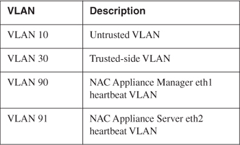
This topology is a collapsed core/distribution layer design with the access switches dual homed to the two core switches. The core switches are running HSRP.
Adding NAC Appliance Managers in High Availability Mode
As you see from the diagram in Figure 12-2, both the serial interface and the eth1 interface are used for the heartbeat packets. eth0 link failure–based failover is also being used.
Figure 12-2. NAC Appliance Manager in HA Mode
The first step in configuring a high-availability pair is adding or modifying their certificates. The certificates of both the primary and secondary Cisco NAC Appliance Managers must be generated using the service IP address or a domain name that DNS resolves to the service IP address. In a production environment, you will want to use a Certificate Authority–signed certificate. For a test environment, you can generate a temporary self-signed certificate in Cisco NAC Appliance Manager.
Adding a CA-Signed Certificate to the Primary NAC Appliance Manager
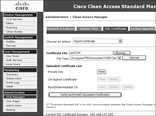
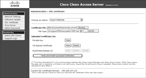
Figure 12-3 shows the certificate configuration page. Remember that the imported certificate must use the service IP address or domain name.
Figure 12-3. CA-Signed Certificate Configuration Page
Follow these steps to add a CA-signed certificate to the primary NAC Appliance Manager:
Step 1. On the Primary Cisco NAC Appliance Manager's admin GUI, navigate to Administration > Clean Access Manager > SSL Certificate.
Step 2. Select Import Certificate from the Choose an Action menu.
Step 3. Browse to your certificate file.
Step 4. Leave the file type to the default value: CA-Signed PEM-encoded X.509 Cert.
Step 5. Click the Upload button.
Step 6. Click Verify and Install Uploaded Certificates.
Step 7. Select Export CSR/PrivateKey/Certificate from the Choose an Action menu.
Step 8. Click Export next to Currently Installed Private Key.
Step 9. Save this export to your hard disk. Later it will be imported into the secondary NAC Appliance Manager.
Generating a Self-Signed Temporary Certificate on the Primary NAC Appliance Manager
Figure 12-4 shows the certificate configuration page.
Figure 12-4. Generate Temporary Certificate Configuration Page
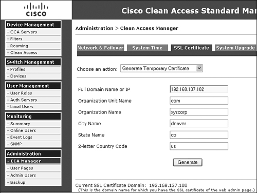
Follow these steps to add a self-signed temporary certificate to the primary Manager. This should be done only for testing purposes.
Step 1. On the Primary Cisco NAC Appliance Manager's admin GUI, navigate to Administration > Clean Access Manager > SSL Certificate.
Step 2. Fill in the Full Domain Name or IP field with the service IP address of the HA pair.
Step 3. Fill in the rest of the form's fields.
Step 4. Click the Generate button.
Step 5. Select Export CSR/PrivateKey/Certificate from the Choose an Action menu.
Step 6. Click Export next to Currently Installed Private Key. Save this export to your hard disk. Later it will be imported into the secondary NAC Appliance Manager.
Step 7. Click Export next to Currently Installed Certificate. Save this export to your hard disk. Later it will be imported into the secondary NAC Appliance Manager.
Adding a Certificate to the Secondary NAC Appliance Manager
Now that the certificate has been added to the primary NAC Appliance Manager, you need to import the private key file and certificate file into the secondary NAC Appliance Manager. The configuration process on the secondary NAC Appliance Manager is the same regardless of whether the primary NAC Appliance Manager used self-signed temporary certificates or Certificate Authority–signed certificates. Use the following steps to configure certificates:
Step 1. On the Secondary Cisco NAC Appliance Manager's admin GUI, navigate to Administration > Clean Access Manager > SSL Certificate.
Step 2. Select Import Certificate from the Choose an Action menu.
Step 3. Browse to the private key file that was exported from the primary NAC Appliance Manager.
Step 4. Choose the file type Private Key.
Step 5. Click Upload.
Step 6. Select Import Certificate from the Choose an Action menu.
Step 7. Browse to your Certificate Authority–signed certificate file.
Step 8. Choose the file type CA-Signed PEM-encoded X.509 Cert.
Step 9. Click Upload.
Step 10. Click Verify and Install Uploaded Certificates.
Configuring High Availability for NAC Appliance Managers
Figure 12-5 is a screen shot of the High Availability configuration on the Primary Manager.
Figure 12-5. Primary NAC Appliance Manager High Availability Configuration
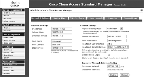
The following are some of the key configuration steps shown in Figure 12-5:
Step 1. Set the High-Availability Mode field to HA-Primary. This setting makes this NAC Appliance Manager the primary, but its role is not permanent. If the primary NAC Appliance Manager fails, the standby becomes the new primary. When the original primary NAC Appliance Manager comes back online, it will assume the standby role.
Step 2. Set the service IP address. This allows the failover pair to appear on the network as a single entity. This IP address is shared between the primary and secondary NAC Appliance Managers. NAC Appliance Servers communicate with the NAC Appliance Manager pair using only the single service IP address.
Note
Be sure to generate your SSL certificate using the service IP address or a domain name that resolves to the service IP address. Both the primary and secondary NAC Appliance Managers will have the same certificate loaded.
Step 3. Set the peer host name. It is critical that this exactly matches the host name defined on the standby NAC Appliance Manager. This value is case sensitive.
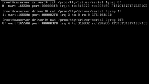
Step 4. Set the correct COM port to use for the heartbeat serial interface. It is highly recommended that a heartbeat serial interface be configured and connected between the Cisco NAC Appliance pair (a standard serial null modem cable is required). Doing so substantially increases the fault tolerance of the NAC Appliance Manager pair.
Step 5. The Disable Serial Login option should be selected only when your NAC Appliance Manager platform has only a single serial port on the motherboard. If you have two serial ports, do not select this option. When you have two ports, the serial login port is always the first tty port, so be sure to attach your heartbeat serial null modem cable to the second serial port.
Figure 12-6. Finding Serial Ports in Linux
Step 6. Set the network address to be used on the mandatory eth1 crossover network. As you can see, the fourth octet of the address is preset. The primary NAC Appliance Manager's IP address will be x.x.x.253; the secondary's will be x.x.x.254.
Step 7. Click Update and then reboot.
To configure the secondary NAC Appliance Manager for high availability, you start by navigating to the GUI of the secondary NAC Appliance Manager: https://eth0_ip_of_secondary/admin. Follow the same instructions as you did for the primary NAC Appliance Manager, except set the High Availability mode to HA-Secondary. It is extremely important that the host names and the peer host names be consistent between the primary and secondary NAC Appliance Managers because the heartbeat mechanism looks at this information when exchanging heartbeat packets.
Adding NAC Appliance Servers in High Availability Mode
When configuring HA on NAC Appliance Servers, it is recommended that you first configure the primary NAC Appliance Server and test it with clients. After successful testing is done, add the secondary server to the system. Testing with only the primary NAC Appliance Server active first will make it easier to troubleshoot any issues. When you add the secondary NAC Appliance Server to the mix, you know you are adding it to a known good working NAC Appliance configuration. As a result, troubleshooting any issues arising from the addition of the secondary NAC Appliance Server will be isolated to only a few possibilities.
The principal configuration steps for configuring High Availability mode for NAC Appliance Servers are the following:
Step 1. Configure the eth2 interfaces.
Step 2. Configure HA on the primary NAC Appliance Server.
Step 3. Test a client—do not continue until this test is successful.
Step 4. Configure HA on the secondary NAC Appliance Server.
Step 5. Connect the NAC Appliance Servers and test.
Step 6. Optionally, configure DHCP failover.
Step 7. Test failing over the pair.
See Figure 12-7 for a sample HA network topology. As shown in Figure 12-7, the serial interface and the eth2 interfaces are used for heartbeat signals. eth2 will be the heartbeat UDP interface. If you do not have an eth2 interface, you can use the eth0 (trusted-side) interface instead. For the serial heartbeat, you can use any available serial port on NAC Appliance Server. If you have only a single serial port, it can be used, but make sure that you disable serial console login when completing the HA configuration steps. The heartbeat serial ports are connected to each other using a null modem cable.
Figure 12-7. Sample NAC Appliance Server HA Network Topology
Configuring the eth2 Interfaces
If you are using eth2 as your heartbeat interface, you will have to configure it manually. This will have to be completed on both the primary and secondary NAC Appliance Servers before HA can be configured. To do this, use the following steps:
Step 1. Use Secure Shell (SSH) to connect to NAC Appliance Server's trusted-side interface. Log in as root.
Step 2. Type cd /etc/sysconfig/network-scripts.
Step 3. List the directory's contents by typing ls.
Step 4. If you do not see a file named ifcfg-eth2, create one by copying ifcfg-eth1 to ifcfg-eth2. Issue the following command:
cp ifcfg-eth1 ifcfg-eth2.
Step 5. Edit ifcfg-eth2:
vi ifcfg-eth2
Step 6. Change the file so that it includes only the following information. Change the values as necessary to match your network topology. The order of the lines is not important.
IPADDR=192.168.0.253
NETMASK=255.255.255.252
BOOTPROTO=static
ONBOOT=yes
BROADCAST=192.168.0.255
DEVICE=eth2
NETWORK=192.168.0.252
Step 7. For the changes to take effect, you must restart the network service:
service network restart
Step 8. Verify that your changes were successful:
ifconfig eth2
The output should show the interface as running and list the new IP address.
Step 9. After both NAC Appliance Servers are complete, issue a ping from one server's eth2 to the other server's eth2 IP address. It should be successful.
Configuring the Primary Server for High Availability
The principal configuration steps for configuring high availability on the primary NAC Appliance Server are as follows:
Step 1. Access the primary NAC Appliance Server directly.
Step 2. Configure the network and host information for the primary NAC Appliance Server.
Step 3. Configure HA-Primary Failover.
Step 4. Configure the SSL certificate.
Step 5. Reboot the primary NAC Appliance Server.
Step 6. Add NAC Appliance Server to NAC Appliance Manager by using the service IP.
Step 7. Complete the configuration and test a client through NAC Appliance.
When these steps are complete, continue on to configure the secondary NAC Appliance Server.
Accessing the Primary Server Directly
NAC Appliance Server has a direct access console GUI. You must use this direct access console to complete the High Availability configuration. These configuration pages are reachable by going directly to NAC Appliance Server at https://eth0_Server_IP/admin. You must access the primary and secondary NAC Appliance Servers in this way for network and HA setup.
Configuring the Network and Host Information for the Primary Server
Before you can configure the failover piece, you must first complete the network and host configuration. Figure 12-8 shows a sample network configuration page. This page is accessed by navigating to Administration > Network Settings > IP.
Figure 12-8. Primary Server Network Settings

Figure 12-8 is shown as a reference so that you can compare the values shown in the figure to those shown later in the HA configuration pages. Some of the key configuration references shown in Figure 12-8 are as follows:
- Because NAC Appliance Server is in Real-IP Gateway mode, it has two unique IP addresses: one for the trusted interface and one for the untrusted interface. If you were running in Virtual Gateway mode, you would have only one IP address for the whole box. Note that this single IP address would be put on both the trusted and untrusted interfaces and would be used for management traffic.
- The Set management VLAN ID option is not checked (disabled). If you were using VLAN trunking, you could check it and assign it to a VLAN, such as VLAN 20. This would instruct NAC Appliance Server that it should respond to only the configured IP address on VLAN 20. This VLAN is typically a dedicated management VLAN. It is checked only on the trusted side of the configuration; this prohibits users on the untrusted side from reaching the NAC Appliance Server management IP address.
Make sure that the NAC Appliance Server is on VLAN X before you set its management VLAN to X. Otherwise, you will not be able to use the IP to reach NAC Appliance Server after the reboot.
The next step is to set the host name and domain name for the Primary Server. To do this, navigate to Administration > Network Settings > DNS. You must fill this page out completely for HA to function. The host name used must be resolvable by DNS or added to the /etc/hosts file of each NAC Appliance Server directly. Record this information for each NAC Appliance Server because it will be needed in the HA configuration.
Now on to the high-availability configuration steps for the primary NAC Appliance Server.
Configuring HA-Primary Failover
When configuring HA, an important piece to consider is what external IPs to choose for the link failure detection–based failover. In Virtual Gateway mode, if NAC Appliance Server initiates traffic destined for an IP that is part of a subnet configured in the managed subnet section, that packet will always be sent out of the eth1 interface except for packets destined for its default gateway. The management subnet of NAC Appliance Server is automatically added to the managed subnet section. Therefore, when you choose the external IP for eth0 link failure detection, it cannot be an IP in the same subnet as NAC Appliance Server (except for the default gateway of NAC Appliance Server). In this scenario, the default gateway address is an HSRP address and is a good choice for the external IP for the eth0 link failure detection.
The external IP for eth1 link failure detection can be any IP that is part of a subnet configured in the managed subnet section. Adding an additional VLAN and subnet in the managed subnet section is recommended. By doing this, you can configure a VLAN switched virtual interface (SVI) on the core switches and use the HSRP address for this new VLAN as the external IP for eth1 link failure detection.
Note
Before configuring HA on NAC Appliance Servers, you must remove them from NAC Appliance Manager if they were previously added to the management domain. This is done by navigating to Device Management > Clean Access Servers > List of Servers and clicking the Delete button next to each NAC Appliance Server.
The High-Availability configuration pages can be accessed only by going to the direct access NAC Appliance Server console located at http://eth0_IP_address/admin. The next step in HA setup is to configure failover. Figure 12-9 shows the failover configuration page from the primary NAC Appliance Server in the sample network shown previously in Figure 12-7.
Figure 12-9. Primary Server Failover Configuration
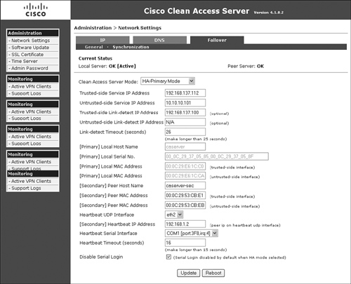
Each field shown in the failover configuration page (see Figure 12-9) is explained in the following list:
- The configuration page shown in Figure 12-9 is accessed by navigating to Administration > Network Settings > Failover.
- Clean Access Server Mode Set Clean Access Server Mode to HA-Primary Mode. This enables all the additional configuration options shown.
- Trusted-Side Service IP Address This is the IP address that is shared between the primary and secondary NAC Appliance Servers. They will communicate to the network using this address.
- Untrusted-Side Service IP Address Set the unique service IP Address. If the server type is set to Virtual Gateway Mode, you would set the untrusted-side service IP address to the same as the trusted-side service IP address.
- Trusted-Side Link Detect (optional) The IP address entered here will be pinged by NAC Appliance Server using its trusted-side interface. The primary and secondary NAC Appliance Servers will typically use the same link detect IP address. This is not a requirement, but a best practice. The pings will be sent out every 2 seconds.
- Untrusted-Side Link Detect (optional) The IP address entered here will be pinged by NAC Appliance Server using its untrusted-side interface. The primary and secondary NAC Appliance Servers will typically use the same link detect IP address. This is not a requirement, but a best practice. The pings will be sent out every 2 seconds.
- Link-Detect Timeout (Seconds) This field must be greater than 25 seconds. When the set timeout expires, the device is considered unreachable. This timeout applies to both trusted and untrusted link detection.
Link detection for the trusted and untrusted sides is another mechanism, like heartbeat serial and UDP, which NAC Appliance Servers can use to detect failures. NAC Appliance Server pings each configured link detect IP address and counts the number of reachable hosts—that is, the number of hosts that did not time out. The count would be between zero and two hosts alive. If the standby NAC Appliance Server has a higher count, meaning it can reach more hosts, a failover occur. If the count is the same for both the active and standby NAC Appliance Servers, no failover occurs. - [Primary] Local Host Name This field is filled out automatically and cannot be changed here.
- [Primary] Local Serial Number This field is filled out automatically and cannot be changed here.
- [Primary] Local MAC Address (Trusted-Side) This field is filled out automatically and cannot be changed here.
- [Primary] Local MAC Address (Untrusted-Side) This field is filled out automatically and cannot be changed here.
Note
It is a good idea to copy the host name, serial number, and trusted and untrusted MAC addresses of the primary NAC Appliance Server to a text file. These will be needed later when configuring HA on the secondary NAC Appliance Server.
To avoid errors, it is best to copy and paste the required secondary NAC Appliance Server information needed in the following list directly from the direct access console of the secondary NAC Appliance server or from a previously created configuration text file.
- [Secondary] Peer Host Name This must exactly match the host name of the secondary NAC Appliance Server. This information will be found or set in the secondary server under Administration > Network Settings > DNS > Host Name.
- [Secondary] Peer MAC Address (Trusted-Side) This must exactly match the MAC address of the eth0 interface of the secondary NAC Application Servers. This value should be copied from the secondary server under Administration > Network Settings > Failover > [Secondary] Local MAC Address (Trusted-Side).
- [Secondary] Peer MAC Address (Untrusted-Side) This must match exactly the MAC address of the eth1 interface of the secondary NAC Appliance Servers. This value should be copied from the secondary server under Administration > Network Settings > Failover > [Secondary] Local MAC Address (Untrusted-Side).
- Heartbeat UDP Interface This defines what interface to send the UDP heartbeat signals across. If available, a dedicated heartbeat interface is recommended (eth2). If not available, use eth0. eth1 should never be used for heartbeats.
- [Secondary] Heartbeat IP Address This is the IP address on the secondary's UDP heartbeat interface.
- Heartbeat Serial Interface Select the COM port to be used to send serial heartbeats across. If you have more than one serial interface on your NAC Appliance Server, using the second interface for heartbeats is recommended. The first interface is reserved for serial login unless disabled in the field following this one.
Caution
Do not connect the serial null modem cable until you have completed HA configuration and rebooted both the primary and secondary NAC Appliance Servers. Unpredictable results could occur.
- Heartbeat Timeout (Seconds) This timeout value is used by both the serial and UDP heartbeat methods. The value must be greater than 15 seconds. If this timer expires on the standby server, a failover will occur. The standby NAC Appliance Server will assume the active role. If both serial and UDP heartbeat methods are configured, both must time out before a failover event will occur. A heartbeat message is sent every 2 seconds.
- Disable Serial Login By default this is checked, meaning that you lose the ability to manage your NAC Appliance Server via a direct connect serial cable. If you have more than one serial interface on your server and you configure the serial heartbeat interface to anything other than the first serial port, you can uncheck this value to maintain serial login capabilities.
- Update Click this button now. Clicking this button updates the information on the failover configuration page but does not reboot the NAC Appliance Server.
- Reboot Do not click Reboot at this point. You will do so later.
Configuring the SSL Certificate of the Primary NAC Appliance Server
A new SSL certificate needs to be generated using the new service IP address just configured in the failover configuration page. To do this, go to the direct console Web GUI of the primary NAC Appliance Server and navigate to Administration > SSL Certificate. Perform one of the following procedures depending on whether you will be using a temporary certificate or a Certificate Authority–signed certificate. It is highly recommended that a Certificate Authority–signed certificate be used in a production environment. Without a Certificate Authority–signed certificate, your clients will see the annoying "accept this certificate?" Windows pop-up message each time they log in.
If you use a Certificate Authority–signed certificate, follow these steps:
Step 1. From the Choose an Action drop-down menu, choose Import Certificate. The page will now look like the one in Figure 12-10.
Figure 12-10. Server's Import Certificate Authority–Signed Certificate Configuration Page
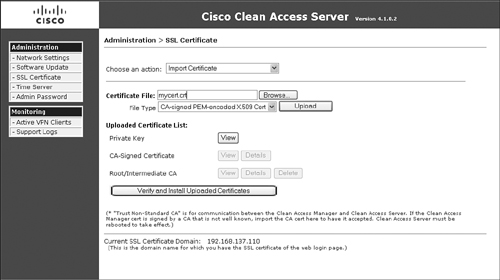
Step 2. In the Certificate field, browse to your certificate file.
Step 3. The File Type menu should show CA-Signed PEM-encoded x.509 Cert. Click the Upload button to import your certificate file.
Step 4. Click Verify and Install Uploaded Certificates.
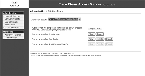
Step 5. Export the private key file to import it on the secondary NAC Appliance Server later. Choose Export CSR/Private Key/Certificate from the Choose an Action drop-down menu.
Step 6. Click Export next to the Currently Installed Private Key option. Save this to your hard drive—it will be imported into the secondary NAC Appliance Server later. Figure 12-11 shows the certificate export page.
Figure 12-11. Certificate Export Configuration Page
If you use a temporary certificate, follow these steps:
Step 1. From the Choose an Action drop-down menu, choose Generate Temporary Certificate.
Step 2. Fill out the form completely.
Step 3. Be sure to use the service IP address or a DNS domain name that resolves to the service IP address of the HA pair when filling out the Full Domain Name section.
Step 4. Click the Generate button.
Step 5. Export the private key file and certificate file to import it on the secondary NAC Appliance Server later. Choose Export CSR/Private Key/Certificate from the Choose an Action drop-down menu.
Step 6. Click Export next to the Currently Installed Private Key option. Save this to your hard drive—it will be imported into the secondary NAC Appliance Server later.
Step 7. Click Export next to the Currently Installed Certificate option. Save this to your hard drive—it will be imported into the secondary NAC Appliance Server later.
Rebooting the Primary Server
Now reboot the primary NAC Appliance Server by navigating to Network Settings > Failover and clicking the Reboot button.
Adding the Primary Server to the Manager
Now you must add the primary server to NAC Appliance Manager. To do so, follow these steps:
Step 1. Open the Manager GUI (https://Service_IP_of_Managers) and navigate to Device Management > CCA Servers > New Server.
Step 2. Add the new NAC Appliance Server to NAC Appliance Manager, being sure to use the service IP address of the HA NAC Appliance Server pair.
Step 3. Click the Add Clean Access Server button. This might take a few minutes to complete.
Step 4. If you are not able to connect, check that you used the service IP address in your primary NAC Appliance Server's certificate file as stated in the "Configuring the SSL Certificate of the Primary NAC Appliance Server" section. In addition, you can check the "Troubleshooting HA" section of this chapter for more assistance.
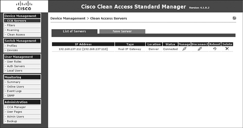
Step 5. Navigate to Device Management > Clean Access Servers > List of Servers. The IP address of the active NAC Appliance Server is listed in brackets next to the service IP for the HA pair, as shown in Figure 12-12. Its status should be Connected. If not, force a connection by clicking the Manage button. If this works, return to the list of IP address servers—the status should now say Connected.
Figure 12-12. List of Servers Showing HA Mode
Completing NAC Appliance Configuration and Testing Client Access
Before continuing on to configuring the secondary NAC Appliance Server, stop here and complete a basic NAC Appliance configuration. This will allow you to test client access to ensure that basic client NAC is working before you enable the complexity of full HA with a secondary NAC Appliance Server. Following the configuration steps outlined in Chapter 8, "The Building Blocks: Roles, Authentication, Traffic Policies, and User Pages," earlier in this book will give you a good basic NAC Appliance configuration to use.
After you complete a basic configuration, plug in a client to the untrusted side of the network and test access. When everything works as you expect, move on to the next section.
Configuring the Secondary Server for High Availability
The principal configuration steps for configuring high availability on the Secondary Server are as follows:
Step 1. Access the Secondary Server directly.
Step 2. Configure the network and host information for the secondary NAC Appliance Server.
Step 3. Configure HA-secondary failover.
Step 4. Configure the SSL certificate.
Step 5. Reboot the secondary NAC Appliance Server.
Step 6. Complete the cable connections and DHCP settings.
Step 7. Test NAC Appliance HA.
Accessing the Secondary Server Directly
The NAC Appliance secondary server has a direct access console GUI. You must use this direct access console to complete the high-availability configuration. These configuration pages are reachable by going directly to NAC Appliance Server at https://eth0_Secondary_Server_IP/admin. You will have to access the primary and secondary NAC Appliance Servers in this way for network and HA setup.
Configuring the Network and Host Information for the Secondary Server
Before you can configure failover, you must first complete the network and host configuration. Figure 12-13 shows the sample network configuration screen from the secondary NAC Appliance Server.
Figure 12-13. Secondary Server Network Settings
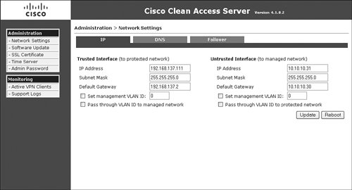
Figure 12-13 is shown as a reference so that you can compare the values shown in the figure to those shown later in the HA configuration pages. Some of the key configuration references shown in Figure 12-13 are the following:
- Because NAC Appliance Server is in Real-IP Gateway mode, it has two unique IP addresses: one for the trusted interface and one for the untrusted interface. If you were running in Virtual Gateway mode, you would have only one IP address for the whole box. Note that this single IP address would be put on both the trusted and untrusted interfaces and would be used for management traffic.
- The Set Management VLAN ID is not checked (it is disabled). If you were using VLAN trunking, you could check it and assign it to a VLAN, such as VLAN 20. This would instruct NAC Appliance Server that it should respond only to the configured IP address on VLAN 20. This VLAN is typically a dedicated management VLAN. It is checked only on the trusted side of the configuration, which prohibits users on the untrusted side from reaching the management IP address of NAC Appliance Server.
Make sure that NAC Appliance Server is on VLAN X before you set its management VLAN to X. Otherwise, you will not be able to use the IP to reach NAC Appliance Server after the reboot.
The next step is to set the host name and domain name for the secondary NAC Appliance Server. To do this, navigate to Administration > Network Settings > DNS. You must fill this page out completely for HA to function. The host name used must be resolvable by DNS or added to the /etc/hosts file of each NAC Appliance Server directly. Record this information for each NAC Appliance Server because it will be needed in the HA configuration.
Configuring HA-Secondary Failover
The HA configuration setup on the secondary NAC Appliance Server is pretty much a mirror copy of the configuration of the HA configuration of the primary NAC Appliance Server. Figure 12-14 shows the HA configuration page of the secondary NAC Appliance Server.
Figure 12-14. Secondary Server HA Configuration

Each field shown in the Failover configuration page of the secondary NAC Appliance Server (see Figure 12-14) is explained in the following list:
- The configuration page shown in Figure 12-14 is accessed by navigating to Administration > Network Settings > Failover.
- Clean Access Server Mode Set Clean Access Server Mode to HA-Secondary Mode. This enables all the additional configuration options shown.
- Trusted-Side Service IP Address This is the IP address that is shared between the primary and secondary NAC Appliance Servers. They will communicate to the network using this address.
- Untrusted-Side Service IP Address Set the service IP for the untrusted side. If your server type is set to Virtual Gateway mode, set the Untrusted-Side Service IP Address field value to the same as the trusted-side service IP address.
- Trusted-Side Link Detect (optional) The IP address entered here will be pinged by NAC Appliance Server using its trusted-side interface. The primary and secondary NAC Appliance Servers will typically use the same link detect IP address. This is not a requirement, but a best practice. The pings will be sent out every 2 seconds.
- Untrusted-Side Link Detect (optional) The IP address entered here will be pinged by NAC Appliance Server using its untrusted-side interface. The primary and secondary NAC Appliance Servers typically use the same link detect IP address. This is not a requirement, but a best practice. Pings will be sent out every 2 seconds.
- Link-Detect Timeout (Seconds) This field must be greater than 25 seconds. When the set timeout expires, the device is considered unreachable. This timeout applies to both trusted and untrusted link detection.
Link detection for the trusted and untrusted sides is another mechanism, like heartbeat serial and UDP, which NAC Appliance Servers can use to detect failures. NAC Appliance Server pings each configured link detect IP address and counts the number of hosts that are reachable—that is, the number of hosts that did not time out. The count would be between zero and two hosts alive. If the standby NAC Appliance Server has a higher count, meaning it can reach more hosts, a failover will occur. If the count is the same for both the active and standby NAC Appliance Servers, no failover occurs. - [Secondary] Local Host Name This field is filled out automatically and cannot be changed here.
- [Secondary] Local Serial Number This field is filled out automatically and cannot be changed here.
- [Secondary] Local MAC Address (Trusted-Side) This field is filled out automatically and cannot be changed here.
- [Secondary] Local MAC Address (Untrusted-Side) This field is filled out automatically and cannot be changed here.
Note
To avoid errors, it is best to copy and paste the required primary NAC Appliance Server information needed from the following list directly from the direct access console of the primary NAC Appliance Server or from a previously created configuration text file.
- [Primary] Peer Host Name This must exactly match the host name of the primary NAC Appliance Server. This information will be found or set in the primary NAC Appliance Server under Administration > Network Settings > DNS > Host Name.
- [Primary] Peer MAC Address (Trusted-Side) This must exactly match exactly the MAC address of the eth0 interface of the primary NAC Appliance Server. This value should be copied from the primary NAC Appliance Server under Administration > Network Settings > Failover > [Primary] Local MAC Address (Trusted-Side).
- [Primary] Peer MAC Address (Untrusted-Side) This must exactly match exactly the MAC address of the eth1 interface of the primary NAC Appliance Server. This value should be copied from the primary NAC Appliance Server under Administration > Network Settings > Failover > [Primary] Local MAC Address (Untrusted-Side).
- Heartbeat UDP Interface This defines what interface to send the UDP heartbeat signals across. If available, a dedicated heartbeat interface is recommended (eth2). If one is not available, use eth0. eth1 should never be used for heartbeats.
- [Primary] Heartbeat IP Address This is the IP address on the UDP Heartbeat interface of the primary NAC Appliance Server.
- Heartbeat Serial Interface Select the COM port to be used to send serial heartbeats across. If you have more than one serial interface on your NAC Appliance Server, using the second interface for heartbeats is recommended. The first interface is reserved for serial login unless it is disabled in the following setting.
Note
Do not connect the serial null modem cable until you have completed HA configuration and rebooted both the primary and secondary NAC Appliance Servers. Otherwise, unpredictable results could occur.
- Heartbeat Timeout (Seconds) This timeout value is used by both the serial and UDP heartbeat methods. The value must be greater than 15 seconds. If this timer expires on the standby NAC Appliance Server, a failover will occur. The standby NAC Appliance Server will assume the active role. If both serial and UDP heartbeat methods are configured, both must time out before a failover event occurs. A heartbeat message is sent every 2 seconds.
- Disable Serial Login This is checked by default, meaning you lose the ability to manage your NAC Appliance Server via a direct connect serial cable. If you have more than one serial interface on your server and you configure the serial heartbeat interface setting to anything other than the first serial port, you can uncheck this value to maintain serial login capabilities.
- Update Click this button now. Doing so updates the information on the failover configuration page but does not reboot NAC Appliance Server.
- Reboot Do not click Reboot at this point. You will do so later.
Configuring the Secondary Server's SSL Certificate
To configure the SSL certificate for the secondary NAC Appliance server, go to the direct console web GUI of the secondary NAC Appliance Server and navigate to Administration > SSL Certificate. Perform one of the following procedures depending on whether you plan to use a temporary certificate or a Certificate Authority–signed certificate. It is highly recommended that a Certificate Authority–signed certificate be used in a production environment. Without a Certificate Authority–signed certificate, your clients will see the annoying "accept this certificate?" Windows pop-up message each time they log in.
If you use a Certificate Authority–signed certificate, follow these steps:
Step 1. From the Choose an Action drop-down menu, select Import Certificate, as shown in Figure 12-15.
Figure 12-15. Importing a Certificate
Step 2. Browse to the previously saved private key file exported from the primary NAC Appliance Server.
Step 3. Choose File Type Private Key and Click Upload.
Step 4. Now import the same certificate file you previously imported into the primary NAC Appliance Server. Browse to the certificate file.
Step 5. Choose File Type CA-Signed PEM-encoded X.509 Cert and click the Upload button.
Step 6. Click the Verify and Install Uploaded Certificates button.
Step 7. Import and install the root or any intermediate certificates as necessary.
If you use a temporary certificate, follow these steps:
Step 1. From the Choose an Action drop-down menu, select Import Certificate.
Step 2. Browse to the previously saved private key file exported from the primary NAC Appliance Server.
Step 3. Choose File Type Private Key and click Upload.
Step 4. Now import the same temporary certificate file you previously exported from the primary NAC Appliance Server. Browse to the certificate file.
Step 5. Choose File Type CA-Signed PEM-encoded X.509 Cert and click the Upload button.
Step 6. Click the Verify and Install Uploaded Certificates button. You should see a Successfully Installed message toward the top of the web page.
Rebooting the Secondary Server
Reboot the secondary NAC Appliance Server by navigating to Network Settings > Failover and clicking the Reboot button.
Complete Cable Connections and DHCP Settings
Now you need to hook up the necessary failover cabling and, optionally, replicate any primary server DHCP settings onto the secondary NAC Appliance Server. The DHCP step applies only if you are using the NAC Appliance DHCP server function to serve IP addresses to your untrusted-side clients.
Note
The DHCP server configuration settings are replicated between the primary and secondary NAC Appliance Servers, but they are not written to disk—only RAM memory on the secondary NAC Appliance Server. To permanently save the DHCP settings, you must do so manually.
In addition, be sure to follow the configuring DHCP failover steps if you are using the DHCP server functions.
Caution
If you remove an HA-pair from NAC Appliance Manager, you will lose all DHCP configurations on both the primary and secondary NAC Appliance Server. The settings will have to be re-added manually and the NAC Appliance Servers rebooted.
Here are the steps to follow for connecting HA cabling:
Step 1. Physically connect the required null modem serial and Ethernet crossover cables that will be used for HA. If you plan to use eth0 as the HA Ethernet card, an additional Ethernet cable will not be necessary.
Step 2. Wait about 45 seconds for the NAC Appliance Servers to link to each other before continuing.
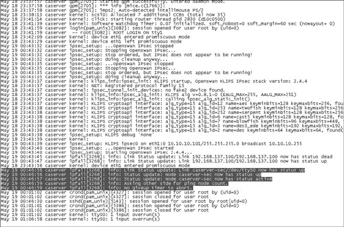
Step 3. To verify that the serial link has come up, use SSH to go to the primary NAC Appliance Server and open the /var/log/messages file. You should see messages similar to those highlighted in Figure 12-16.
Figure 12-16. Serial Link Log Messages
Here are the steps to follow for optional DHCP configuration:
Step 1. Shut down the primary NAC Appliance Server. To do this, use SSH to go to the primary NAC Appliance Server as root and issue the service perfigo stop command-line interface (CLI) command before issuing the shutdown command or clicking the power button. This will prevent a data corruption of the NAC Appliance files.
Step 2. Navigate to Device Management > Clean Access Servers > List of Servers. The IP address of the active NAC Appliance Server is listed in brackets next to the service IP for the HA pair. The active IP address now should match that of the secondary NAC Appliance Server because the primary NAC Appliance Server is off.
Note
To find the active or standby status of a server from the CLI, you can run the fostate.sh shell script. This script can be found in the directory of your last upgrade, such as /store/cca_upgrade-4.1.0.2. To run it, issue the command ./fostate.sh in the proper directory.
Step 3. Now configure the DHCP server settings on the secondary NAC Appliance Server to mirror what was done previously on the primary NAC Appliance Server. To do this, click the Manage icon for the HA pair. Doing so brings up the management pages for the active NAC Appliance Server, which is currently the secondary NAC Appliance Server.
Step 4. Navigate to Network > DHCP. Configure the DHCP settings to match those on your primary NAC Appliance Server.
Continue on to test the NAC Appliance HA.
Testing NAC Appliance HA
Finally, you need to test the HA setup to ensure that it works properly. If you are using the DHCP server function, configure DHCP failover before continuing your HA testing. You will need a client machine connected to the untrusted side of the network. In your current setup, the primary NAC Appliance Server has been turned off, and the secondary NAC Appliance Server is currently the active server. Now turn on the primary NAC Appliance Server, and wait for it to completely boot up before continuing. The secondary NAC Appliance Server should still be the active server even after the primary NAC Appliance Server comes online. The primary server will assume the standby server role. Verify this by navigating to Device Management > CCA Servers > List of Servers. The secondary NAC Appliance Server's IP address should be listed in brackets.
To test the HA setup, follow these steps:
Step 1. Issue a DHCP release/renew on your client test machine. Ensure that you receive a proper IP address.
Step 2. Log in to NAC Appliance. You should now be logged in via the secondary NAC Appliance Server.
Step 3. Start a continuous ping from the client to a reachable host on the trusted side.
Step 4. Now reboot the secondary NAC Appliance Server. This should force a failover and make the primary NAC Appliance Server become the active NAC Appliance Server. The client will briefly lose connectivity—watch the pings.
Step 5. After about 15 seconds, verify this by navigating to Device Management > CCA Servers > List of Servers and periodically refreshing the screen. The IP address of the primary NAC Appliance Server should be listed in brackets.
Step 6. The client's connectivity should be restored in about 16 seconds. Traffic is now going through the primary NAC Appliance Server.
Step 7. To test DHCP failover, issue a DHCP release/renew on the client machine. Check to make sure that you receive a proper IP address.
Step 8. After the secondary NAC Appliance Server reboots and comes back online, it will assume the standby role.
Step 9. You can view the event log on NAC Appliance Manager by navigating to Monitoring > Event Logs. You will see messages similar to "HA status alert of Clean Access Server: caserver up."
Setting Up DHCP Failover on NAC Appliance Servers
When using the DHCP Server mode on a NAC Appliance HA pair, you need to configure DHCP failover. Doing so allows for the constant synchronization of DHCP-related information (for example, active leases, lease expirations, and so on) between the primary and secondary NAC Appliance Servers. As a result, when a failover occurs, the new active NAC Appliance Server picks up exactly where the old active NAC Appliance Server left off. DHCP failover works by setting up an SSH-encrypted tunnel between the primary and secondary NAC Appliance Servers. For the SSH tunnel to be established, keys must be exchanged between servers. To complete the DHCP failover setup, follow these steps:
Step 1. Open two web browsers. Point one at the web GUI (https://IP_primary_Server/admin) of the primary NAC Appliance Server and one at the web GUI of the secondary NAC Appliance Server.
Step 2. On the primary NAC Appliance Server, navigate to Administration > Network Settings > Failover > Synchronization.
Step 3. On the secondary NAC Appliance Server, navigate to Administration > Network Settings > Failover > Synchronization.
Step 4. Click the Enable button on both NAC Appliance Servers. This will generate a client SSH key.
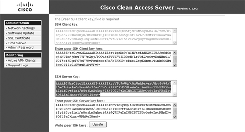
Step 5. Now copy and paste the client and server SSH keys between the primary and secondary NAC Appliance Servers.
Step 6. Click the Update button on the secondary NAC Appliance Server.
Step 7. Click the Update button on the primary NAC Appliance Server.
Step 8. Reboot both NAC Appliance Servers now. A reboot is required to create the /var/state/dhcp directories and files on both the primary and secondary NAC Appliance Servers.
The SSH tunnel should now be established. Figure 12-17 shows the synchronization page of the primary NAC Appliance Server. Figure 12-18 shows the synchronization page of the secondary NAC Appliance Server.
Figure 12-17. HA Synchronization Page of the Primary NAC Appliance Server
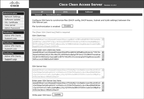
Figure 12-18. HA Synchronization Page of the Secondary NAC Appliance Server
Troubleshooting HA
Most of your troubleshooting will be done using the event log found on the web GUI of the NAC Appliance Manager and the individual log files on the NAC Appliance Servers themselves. To change the level of logging detail on the NAC Appliance Servers and to download the log files, navigate to Monitoring > Support Logs. Figure 12-19 highlights the most useful files for HA troubleshooting purposes.
Figure 12-19. HA Troubleshooting Log Files

Summary
This chapter examined how NAC Appliance Manager and NAC Appliance Server High Availability mode works and is configured. Because both NAC Appliance Manager and NAC Appliance Server are critical components of your NAC Appliance solution, designing a high-availability solution for them is strongly recommended. Without high availability enabled, you run the risk of impairing your clients' capability to access the network.
The chapter includes the following recommendations for NAC Appliance Manager in High Availability mode:
- Use both the serial link and the eth1 interface for the heartbeat packets.
- Use eth0 link failure detection–based failover.
- The external IP address used for eth0 link failure detection can be the HSRP address on the core switch configured for the management VLAN of NAC Appliance Manager or some other high-availability IP address.
- Use a Certificate Authority–signed certificate file in a production environment.
The chapter includes the following recommendations for NAC Appliance Server in High Availability mode:
- Use both the serial link and the eth2 interface for the heartbeat packets.
- Use eth0 and possibly eth1 link failure detection-based failover.
- The external IP address used for the eth0 link failure detection can be the HSRP address on the core switches configured for the management VLAN of NAC Appliance Manager or any other highly available IP address on the trusted part of the network.
- The external IP address used for the eth1 link failure detection can be the HSRP address on the core switches configured for one of the managed subnets of NAC Appliance Server or any other highly available IP address on the untrusted part of the network.
- Use a Certificate Authority–signed certificate file in a production environment.