This chapter includes the following topics:
The previous chapters have discussed how to align network resources with business priority and application requirements, as well as techniques that can be applied within the network and accelerator devices to improve the overall performance of an application over the network. Techniques employed in the network, such as quality of service (QoS), can help align available network capacity with application throughput requirements or adjust queuing and scheduling for a specific application that might be latency sensitive. Application data caching, read-ahead, prediction, and CDN capabilities can help mitigate the unnecessary utilization of bandwidth for redundant object transfers and also mitigate latency by handling the majority of the workload locally or in a more optimized fashion.
You can, however, employ more generic layers of optimization, which can work across multiple applications concurrently. This type of optimization, commonly called WAN optimization, generally refers to functions that are commonly found in accelerator devices (such as standalone appliances or router-integrated modules) that overcome performance limitations caused by transport protocols, packet loss, and capacity limitations.
WAN optimization capabilities make the WAN a more tolerable place for applications to live by removing the vast majority of performance barriers that the WAN creates. For instance, advanced network compression can be applied to improve performance by minimizing the amount of data that needs to traverse the WAN. A secondary benefit of this is that, in many cases, fewer exchanges of data need to occur over the WAN as well, thereby mitigating the latency associated with the number of roundtrip exchanges that would have been necessary. TCP optimization, on the other hand, is commonly used to allow nodes to more efficiently use available resources and minimize the impact of loss and latency in a WAN.
This chapter examines how WAN optimization capabilities overcome performance barriers created by WAN conditions. Keep in mind that, in terms of accelerator products, you can use WAN optimization capabilities in conjunction with other optimization technologies that are application-specific, as described in Chapter 4, “Overcoming Application-Specific Barriers.” Furthermore, assuming the architecture of the accelerator is transparent, you can use these optimization technologies in conjunction with network-oriented functions that provide visibility and control.
What is a transport protocol and how does it create performance limitations? Most people wonder how TCP (or other transport protocols) could ever become a bottleneck, simply because it always seems to just “work.” In an internetwork, a layer must exist between applications and the underlying network infrastructure. This layer, called the transport layer, not only helps to ensure that data is moved between nodes, but also helps nodes understand how the network is performing so that they can adapt accordingly.
While the transport layer is an unlikely candidate for application performance woes, it can become a problem, primarily because the transport protocols in broad use today were designed in 1981. Today’s application demands and network topologies differ greatly from the networks of the early 1980s. For instance, 300 baud was considered blazing fast at the time that TCP was created. Congestion was largely due to a handful of nodes on a shared network of limited scale rather than the complex, high-speed, hierarchical networks such as the Internet, which is plagued with oversubscription, aggregation, and millions of concurrent users each contending for available bandwidth. Applications in 1981 were commonly text-oriented applications (and largely terminal-oriented), whereas today even the most ill-equipped corporate user can easily move files that are tens upon hundreds of megabytes in size during a single transfer.
Although the network has changed, TCP remains relevant in today’s dynamic and ever-changing network environment. TCP has undergone only minor changes in the past 25 years, and those changes are in the form of extensions rather than wholesale rewrites of the protocol. Although there are some more modern transport protocols that have roots in TCP, many are considered developmental projects only and currently have limited deployment in the mainstream.
Another important consideration relative to today’s enterprise networking and application environments is the cost and available capacity of LAN technology versus declining WAN technology costs. In effect, network bandwidth capacity has steadily increased over the past 20 years; however, the cost of LAN bandwidth capacity has dropped at a rate that is more dramatic per bit/second than the rate at which the cost of an equivalent amount of WAN bandwidth capacity has dropped.
The ever-increasing disparity between WAN and LAN bandwidth presents challenges in the form of throughput. Applications and access to content have become more enabled for LAN users as LAN bandwidth has increased; however, the same level of access to those applications and content has not become more enabled for WAN users given the far different cost versus bandwidth capacity increase metrics that the WAN has undergone. Put simply, the rate of bandwidth increase found in the WAN is not keeping pace with the LAN, and this creates performance challenges for users who are forced to access information over the WAN. In this way, the LAN has enabled faster access to a much more network-intensive set of data. At the same time, the WAN has not grown to the same degree from a capacity perspective or become achievable from a price perspective to allow the same level of access for nearly the same cost.
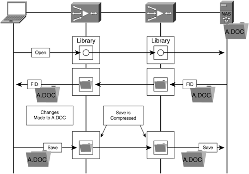
WAN optimization techniques (discussed later in this chapter, in the section “Accelerators and Compression”) are considered adjacent and complementary to the techniques presented in earlier chapters; that is, they are implemented apart from network optimization (QoS and optimized routing) and application acceleration (caching, CDN, and other optimizations such as read-ahead). For instance, an object-layer application cache can leverage compression technologies during content distribution or pre-position jobs to improve throughput and ensure that the compression history is populated with the relevant content if the transfer of the objects in question takes place over the WAN.
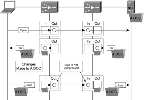
In the opposite direction, a user has a read-write type of relationship with an object that has been opened through an accelerator’s object cache, where that object has been validated against the origin server (in the case of a cached file). If that file is saved and written back to the origin server, the compression history and protocol optimizations (such as write-back optimization) can be leveraged to improve the write performance while saving bandwidth.
Compression techniques can be leveraged to minimize the bandwidth consumed and eliminate previously seen repetitive byte patterns. This not only helps to ensure that precious WAN bandwidth is conserved but also serves to improve the performance of the user experience because less bandwidth is needed. Consequently, fewer packet exchanges must occur before the operation completes.
Coupling compression and the application acceleration techniques discussed in previous chapters with optimizations to the transport protocol ensures that the WAN is used efficiently and the user experience is significantly optimized. In many cases, WAN users experience performance levels similar to those experienced when operating in a LAN environment. WAN optimization helps to overcome the constraints of the WAN while maintaining WAN cost metrics, preserving investment, and providing a solution for consolidating distributed server, storage, and application infrastructure.
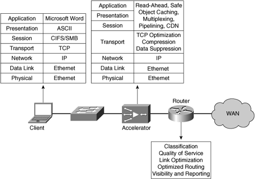
Put simply, the network is the foundation for an application-fluent infrastructure, and an optimized foundation provides the core for application performance. Transport protocol optimization and compression (that is, WAN optimization) ensure that resources are used effectively and efficiently while overcoming performance barriers at the data transmission layer. Application acceleration works to circumvent application layer performance barriers. These technologies are all independent but can be combined cohesively to form a solution, as shown in Figure 6-1.
TCP is the most commonly used transport protocol for applications that run on enterprise networks and the Internet today. TCP provides the following functions:
Connection-oriented service between application processes on two nodes that are exchanging data
Guaranteed delivery of data between these two processes
Bandwidth discovery and congestion avoidance to fairly utilize available bandwidth based on utilization and WAN capacity
Note
For more information about TCP, see RFC 793, which you can access through the following link: http://www.rfc-editor.org/rfcsearch.html
Before data can be sent between two disparate application processes on two disparate nodes, a connection must first be established. Once the connection is established, TCP provides guaranteed reliable delivery of data between the two application processes.
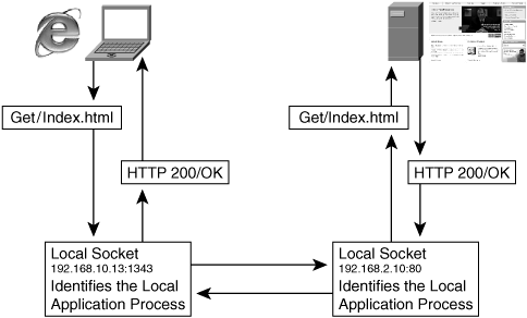
The TCP connection is established through a three-way handshake agreement that occurs between two sockets on two nodes that wish to exchange data. A socket is defined as the network identifier of a node coupled with the port number that is associated with the application process that desires to communicate with a peer. The use of TCP sockets is displayed in Figure 6-2.
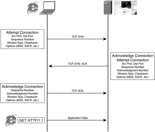
During the establishment of the connection, the two nodes exchange information relevant to the parameters of the conversation. This information includes
Source and destination TCP ports: The ports that are associated with application processes on each of the nodes that would like to exchange application data.
Initial sequence number: Each device notifies the other what sequence number should be used for the beginning of the transmission.
Window size: The advertised receive window size; that is, the amount of data that the advertising node can safely hold in its socket receive buffer.
Options: Optional header fields commonly used for extensions to TCP behavior. For instance, this could include features such as window scaling and selective acknowledgment that were not included as part of the TCP RFC but can augment TCP behavior (an authoritative list of TCP options can be found at http://www.iana.org/assignments/tcp-parameters).
For instance, if an Internet user wants to use Internet Explorer to access http://www.cisco.com, the user’s computer would first have to resolve the name www.cisco.com to an IP address, and then attempt to establish a TCP connection to the web server that is hosting www.cisco.com using the well-known port for HTTP (TCP port 80) unless a port number was specified. If the web server that is hosting www.cisco.com is accepting connections on TCP port 80, the connection would likely establish successfully. During the connection establishment, the server and client would tell one another how much data they can receive into their socket buffer (window size) and what initial sequence number to use for the initial transmission of data. As data is exchanged, this number would increment to allow the receiving node to know the appropriate ordering of data. During the life of the connection, TCP employs checksum functionality to provide a fairly accurate measure of the integrity of the data.
Once the connection is established between two nodes (IP addresses) and two application process identifiers (TCP ports), the application processes using those two ports on the two disparate nodes can begin to exchange application layer data. For instance, once a connection is established, a user can submit a GET request to the web server that it is connected to in order to begin downloading objects from a web page, or a user can begin to exchange control messages using SMTP or POP3 to transmit or receive an e-mail message. TCP connection establishment is shown in Figure 6-3.
Once transmission commences, application data is drained from application buffers on the transmitting process into the node’s socket buffer. TCP then negotiates the transmission of data from the socket transmission buffer to the recipient node (that is, the draining of the buffer) based on the availability of resources on the recipient node to receive the data as dictated by the initially advertised window size and the current window size. Given that application data blocks may be quite large, TCP performs the task of breaking the data into segments, each with a sequence number that identifies the relative ordering of the portions of data that have been transmitted. If the node receives the segments out of order, TCP can reorder them according to the sequence number. If TCP buffers become full for one of the following reasons, a blocking condition could occur:
TCP transmit buffer becomes full: The transmit buffer on the transmitting node can become full if network conditions prevent delivery of data or if the recipient is overwhelmed and cannot receive additional data. While the receiving node is unable to receive more data, applications may be allowed to continue to add data to the transmit buffer to await service. With the blockade of data waiting in the transmit buffer, unable to be transmitted, applications on the transmitting node may become blocked (that is, momentary or prolonged pauses in transmission). In such a situation, new data cannot be written into the transmit buffer on the transmitting node unless space is available in that buffer, which generally cannot be freed until the recipient is able to receive more data or the network is able to deliver data again.
TCP receive buffer becomes full: Commonly caused by the receiving application not being able to extract data from the socket receive buffer quickly enough. For instance, an overloaded server, i.e. one that is receiving data at a rate greater than the rate at which it can process data, would exhibit this characteristic. As the receive buffer becomes full, new data cannot be accepted from the network for this socket and must be dropped, which indicates a congestion event to the transmitting node.
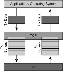
Figure 6-4 shows how TCP acts as an intermediary buffer between the network and applications within a node.
When data is successfully placed into a recipient node TCP receive buffer, TCP generates an acknowledgment (ACK) with a value relative to the tail of the sequence that has just been received. For instance, if the initial sequence number was “1” and 1 KB of data was transmitted, when the data is placed into the recipient socket receive buffer, the recipient TCP stack will issue an ACK with a value of 1024. As data is extracted from the recipient node’s socket receive buffer by the application process associated with that socket, the TCP stack on the recipient will generate an ACK with the same acknowledgment number but will also indicate an increase in the available window capacity. Given that applications today are generally able to extract data immediately from a TCP receive buffer, it is likely that the acknowledgment and window relief would come simultaneously.
The next segment that is sent from the transmitting node will have a sequence number equal to the previous sequence number plus the amount of data sent in the previous segment (1025 in this example), and can be transmitted only if there is available window capacity on the recipient node as dictated by the acknowledgments sent from the recipient. As data is acknowledged and the window value is increased (data in the TCP socket buffer must be extracted by the application process, thereby relieving buffer capacity and thus window capacity), the sender is allowed to continue to send additional data to the recipient up to the maximum capacity of the recipient’s window (the recipient also has the ability to send dynamic window updates indicating increases or decreases in window size).
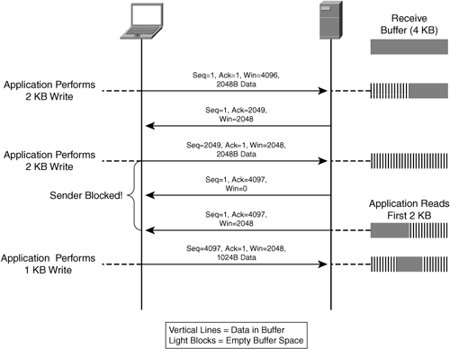
This process of transmitting data based on the recipient’s ability to receive and previously acknowledged segments is commonly referred to as the TCP sliding window. In essence, as the recipient continues to receive and acknowledge or otherwise notify of an increase in window size, the window on the transmitting node shifts to allow new data to be sent. If at any point buffers become full or the window is exhausted, the recipient must first service data that has been previously received and acknowledge the sender before any new data can be sent. An example of this process is shown in Figure 6-5.
Additionally, TCP provides a flag that allows an application process to notify TCP to send data immediately rather than wait for a larger amount of data to accumulate in the socket buffer. This flag, called a push, or PSH, instructs TCP to immediately send all data that is buffered for a particular destination. This push of data also requires that previous conditions be met, including availability of a window on the recipient node. When the data is transmitted, the PSH flag in the TCP header is set to a value of 1, which also instructs the recipient to send the data directly to the receiving application process rather than use the socket receive buffer.
Nodes that are transmitting also use the acknowledgment number, sequence number, and window value as a gauge of how long to retain data that has been previously transmitted. Each segment that has been transmitted and is awaiting acknowledgment is placed in a retransmission queue and is considered to be unacknowledged by the recipient application process. When a segment is placed in the retransmission queue, a timer is started indicating how long the sender will wait for an acknowledgment. If an acknowledgment is not received, the segment is retransmitted. Given that the window size is generally larger than a single segment, many segments are likely to be outstanding in the network awaiting acknowledgment at any given time.
From a transport layer perspective, the loss of a segment might not prevent transmission from continuing. However, given that the application layer is really dictating transport layer behavior (for instance, an upper-layer protocol acknowledgment), the loss of a segment may indeed prevent transmission from continuing.
The purpose of this retransmission queue is twofold:
It allows the transmitting node to allocate memory capacity to retain the segments that have been previously transmitted. If a segment is lost (congestion, packet loss), it can be transmitted from the retransmission queue, and remains there until acknowledged by the recipient application process (window update).
It allows the original segment, once placed in the retransmission queue, to be removed from the original transmission queue. This in effect allows TCP to be continually extracting data from the local transmitting application process while not compromising the transmitting node’s ability to retransmit should a segment become lost or otherwise unacknowledged.
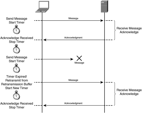
An example of TCP retransmission management is shown in Figure 6-6.
The TCP sliding window can act as a throttling mechanism to ensure that transmission of data is done in such a way that it aligns with the available buffer capacity and window of the two devices exchanging data. There are also mechanisms in TCP that allow it to act as a throttling mechanism based on the capacity of the network and any situations encountered in the network.
In some cases, the nodes exchanging data are able to send more data than the network can handle, and in other cases (which is more prominent today), the nodes are not able to send as much data as the network can handle. In the case of nodes being able to transmit more data than the network is prepared to handle, congestion and loss occur. TCP has mechanisms built in to account for these situations. In this way, TCP is adaptive in that it bridges the gap between transmission requirements and limitations, receive requirements and limitations, congestion, and loss, for both the application process and the network. This throttling mechanism also provides a balancing act between applications and the network and works to continually leverage what capacity in the network is available while attempting to maximize application throughput.
Discovering the steady state for an application process, meaning the balance between available network capacity and the rate of data exchange between application processes and socket buffers, is wholly subjective because application behavior is largely dictated by the function of input, meaning the rate at which the application attempts to send or receive data from the socket buffers. Network throughput is generally more deterministic and objective based on a variety of factors (which would otherwise make it appear nondeterministic and fully subjective), including bandwidth, latency, congestion, and packet loss.
The terms congestion and loss are used separately here, even though congestion and loss are generally married. In some situations, congestion can simply refer to a delay in service due to saturated buffers or queues that are not completely full, but full enough to slightly delay the delivery of a segment of data. These factors are deterministic based on network utilization and physics rather than a set of input criteria, as would be the case with an application. In any case, applications are driving the utilization of network bandwidth, so the argument could be made that they go hand in hand.
TCP provides capabilities to respond to network conditions, thus allowing it to perform the following basic but critical functions:
Initially find a safe level at which data can be transmitted and continually adapt to changes in network conditions
Respond to congestion or packet loss events through retransmission and make adjustments to throughput levels
Provide fairness when multiple concurrent users are contending for the same shared resource (bandwidth)
These capabilities are implemented in two TCP functions that are discussed in the next two sections: TCP slow start and TCP congestion avoidance.
TCP is responsible for initially finding the amount of network capacity available to the connection. This function, as introduced in Chapter 2, “Barriers to Application Performance,” is provided in a mechanism found in TCP called slow start (also known as bandwidth discovery) and is also employed in longer-lived connections when the available window falls below a value known as the slow-start threshold. Slow start is a perfect name for the function, even though it may appear upon further examination to be a misnomer.
Slow start uses an exponential increase in the number of segments that can be sent per successful round trip, and this mechanism is employed at the beginning of a connection to find the initial available network capacity. In a successful round trip, data is transmitted based on the current value of the congestion window (cwnd) and an acknowledgment is received from the recipient. (The cwnd correlates to the number of segments that can be sent and remain unacknowledged in the network and is a dynamic value that cannot exceed the window size of the recipient.) The cwnd value is bound to an upper threshold defined by the receiver window size and the transmission buffer capacity of the sender.
With TCP slow start, the transmitting node starts by sending a single segment and waits for acknowledgment. Upon acknowledgment, the transmitting node doubles the number of segments that are sent and awaits acknowledgment. This process occurs until one of the following two scenarios is encountered:
An acknowledgment is not received, thereby signaling packet loss or excessive congestion
The number of segments that can be sent (cwnd) is equal to the window size of the recipient or equal to the maximum capacity of the sender
The first case is only encountered in the following circumstances:
The capacity of the network is less than the transmission capabilities of the sender and receive capabilities of the receiver
A loss event is detected (no acknowledgment received within the time allocated to the transmitted segment as it is placed in the retransmission queue)
Congestion delays the delivery of the segment long enough to allow the retransmission queue timer for the transmitted segment to expire
The second case is encountered only when the capacity of the network is equal to (with no loss or congestion) or greater than the transmission capabilities of the sender and the receive capabilities of the receiver. In this case, the sender or the receiver cannot fully capitalize on the available network capacity based on window capacity or buffer sizes.
The result of TCP slow start is an exponential increase in throughput up to the available network capacity or up to the available transmit/receive throughput of the two nodes dictated by buffer size or advertised window size. This is a relatively accurate process of finding the initially available bandwidth, and generally is skewed only in the case of a network that is exhibiting high packet loss characteristics, which may cut the slow-start process short. When one of the previously listed two cases presented is encountered, the connection exits TCP slow start, knowing the initially available network capacity, and enters the congestion avoidance mode. Slow start is never entered again unless the cwnd of the connection falls below the slow-start threshold value.
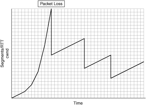
If the first case is encountered—loss of a packet, or excessive delay causing the retransmission timer to expire—standard TCP implementations immediately drop the cwnd value by 50 percent. If the second case is encountered—no loss—cwnd is in a steady state that is equal to the receiver’s advertised window size. TCP slow start is shown in Figure 6-7.
Once the TCP connection exits slow start (bandwidth discovery), it then enters a mode known as congestion avoidance. Congestion avoidance is a mechanism that allows the TCP implementation to react to situations encountered in the network. Packet loss and delay signal congestion in the network, which could be indicative of a number of factors:
Bandwidth allocation change: For instance, change in a variable bandwidth circuit can result in the network being able to service more or less overall throughput based on the direction and nature of the change.
Network oversubscription: When a shared network connection between upstream devices is used by multiple concurrent users, it can become congested to the point of loss or delay.
Congestion of device queues: Similar to network oversubscription, a shared device such as a router can have its queues exhausted to the point of not being able to accept new packets. This could also be equated to a QoS configuration that dictates maximum bandwidth utilization of a specific traffic class or drop policies for that class when congestion is encountered.
Overload of destination: Destination socket buffers can become full because of an application’s inability to drain data from them in a timely fashion, potentially because of the server being overwhelmed.
This list only begins to scratch the surface of why packets could be lost or otherwise delayed. The good news is that TCP was designed to work in a network that is unreliable and lossy (high levels of packet loss) and uses these events to its advantage to adequately throttle transmission characteristics and adapt to network conditions.
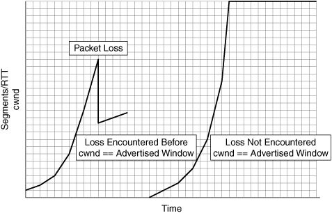
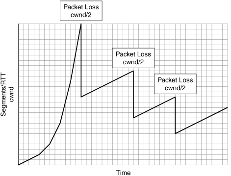
While in congestion avoidance mode, standard TCP continually increments the number of segments that can be transmitted without acknowledgment by one for every successful round trip, up to the point where cwnd has parity with the recipient’s advertised window size. Any time a loss is detected (the retransmission timer for a segment expires), standard TCP reduces cwnd by 50 percent, thereby minimizing the amount of data that can be unacknowledged in the network (in other words, in transit), which can directly impact the ability of the sender to transmit data. TCP congestion avoidance is shown in Figure 6-8.
Through the use of slow start and congestion avoidance mode, TCP can discover available network capacity for a connection and adapt the transmission characteristics of that connection to the situations encountered in the network.
Now that you understand the fundamentals of how TCP operates, you are ready to examine how TCP can become a barrier to application performance in WAN environments. If you are wondering whether TCP can also be a barrier to application performance in LAN environments, the answer is unequivocally “yes.” However, given that this book focuses on application acceleration and WAN optimization, which are geared toward improving performance for remote office and WAN environments, this book will not examine the TCP barriers to application performance in LAN environments.
You may also be wondering about UDP at this point. UDP, which is connectionless and provides no means for guaranteed delivery (it relies on application layer semantics), generally is not limited in terms of throughput on the network (outside of receiver/transmitter buffers). It is also not considered a good network citizen, particularly on a low-bandwidth WAN, because it consumes all available capacity that it can with no inherent fairness characteristics. Most enterprise applications, other than Voice over IP, video, TFTP, and some storage and file system protocols, do not use UDP. UDP traffic is generally best optimized in other ways, including stream splitting for video, which is discussed in Chapter 4, or through packet concatenation or header compression for VoIP. These topics, including UDP in general, are not discussed in the context of WAN optimization in this work.
The previous section examined at a high level how TCP provides connection-oriented service, provides guaranteed delivery, and adapts transmission characteristics to network conditions. TCP does have limitations, especially in WAN environments, in that it can be a significant barrier to application performance based on how it operates. This section examines ways to circumvent the performance challenges presented by TCP, including slow start and congestion avoidance, but note that this will not be an exhaustive study of every potential extension that can be applied.
No, this is not a John Steinbeck novel gone wrong. “Mice” and “elephants” are two of the creatures that can be found in the zoo known as networking. The term mice generally refers to very short-lived connections. Mice connections are commonly set up by an application to perform a single task, or a relatively small number of tasks, and then torn down. Mice connections are often used in support of another, longer-lived connection. An example of mice connections can be found in HTTP environments, where a connection is established to download a container page, and ancillary connections are established to fetch objects. These ancillary connections are commonly torn down immediately after the objects are fetched, so they are considered short-lived, or mice, connections.
Elephants are not connection related; rather, the term elephant refers to a network that is deemed to be “long” and “fat.” “Elephant” is derived from the acronym for long fat network, LFN. An LFN is a network that is composed of a long distance connection (“long”) and high bandwidth capacity (“fat”).
The next two sections describe mice connections and elephant networks, and the performance challenges they create.
Short-lived connections suffer from performance challenges because each new connection that is established has to undergo TCP slow start. As mentioned earlier, TCP slow start is a misnomer because it has very fast throughput ramp-up capabilities based on bandwidth discovery but also can impede the ability of a short-lived connection to complete in a timely fashion. Slow start allows a new connection to use only a small amount of available bandwidth at the start, and there is significant overhead associated with the establishment of each of these connections, caused by latency between the two communicating nodes.
A good example of a short lived connection is a Web browser’s fetch of a 50-KB object from within an HTTP container page. Internet browsers spawn a new connection specifically to request the object, and this new connection is subject to TCP slow start. With TCP slow start, the connection is able to transmit a single segment (cwnd is equal to one segment) and must wait until an acknowledgment is received before slow start doubles the cwnd value (up to the maximum, which is the receiver’s advertised window size). Due to TCP slow start, only a small amount of data can be transmitted, and each exchange of data suffers the latency penalty of the WAN.
Once the connection is in congestion avoidance (assuming it was able to discover a fair amount of bandwidth), it would be able to send many segments without requiring tedious acknowledgments so quickly. If the initial segment size is 500 bytes, it would take a minimum of seven roundtrip exchanges (not counting the connection setup exchanges) to transfer the 50-KB object, assuming no packet loss was encountered. This is shown in Table 6-1.
In a LAN environment, this series of exchanges would not be a problem, because the latency of the network is generally around 1–2 ms, meaning that the total completion time most likely would be under 20 ms. However, in a WAN environment with 100 ms of one-way latency (200 ms round trip), this short-lived connection would have taken approximately 1.4 seconds to complete. The challenges of TCP slow start as it relates to short-lived connections is, in effect, what gave birth to the term “World Wide Wait.”
There are two primary means of overcoming the performance limitations of TCP slow start:
Circumvent it completely by using a preconfigured rate-based transmission protocol. A rate-based transmission solution will have a preconfigured or dynamically learned understanding of the network capacity to shape the transmission characteristics immediately, thereby mitigating slow start.
Increase the initial permitted segment count (cwnd) to a larger value at the beginning of the connection, otherwise known as large initial windows. This means of overcoming performance limitations of TCP slow start is generally the more adaptive and elegant solution, because it allows each connection to continue to gradually consume bandwidth rather than start at a predefined rate.
Using a preconfigured rate-based transmission solution requires that the sender, or an intermediary accelerator device, be preconfigured with knowledge of how much capacity is available in the network, or have the capability to dynamically learn what the capacity is. When the connection is established, the node (or accelerator) immediately begins to transmit based on the preconfigured or dynamically learned rate (that is, bandwidth capacity) of the network, thereby circumventing the problems of TCP slow start and congestion avoidance.
In environments that are largely static (bandwidth and latency are stable), rate-based transmission solutions work quite well. However, while rate-based transmission does overcome the performance challenges presented by TCP slow start and congestion avoidance, it has many other challenges and limitations that make it a less attractive solution for modern-day networks.
Today’s networks are plagued with oversubscription, contention, loss, and other characteristics that can have an immediate and profound impact on available bandwidth and measured latency. For environments that are not as static, a rate-based transmission solution will need to continually adapt to the changing characteristics of the network, thereby causing excessive amounts of measurement to take place such that the accelerator can “guesstimate” the available network capacity. In a dynamic network environment, this can be a challenge for rate-based transmission solutions because network congestion, which may not be indicative of loss or changes in bandwidth, can make the sender believe that less capacity is available than what really is available.
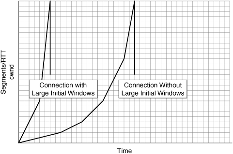
Although rate-based transmission solutions may immediately circumvent slow start and congestion avoidance to improve performance for short- and long-lived connections, a more adaptive solution with no restrictions is available by using large initial windows. Large Initial Windows, originally defined in RFC 3390, “Increasing TCP’s Initial Window,” specifies that the initial window be increased to minimize the number of roundtrip message exchanges that must take place before a connection is able to exit slow start and enter congestion avoidance mode, thereby allowing it to consume network bandwidth and complete the operation much more quickly. This approach does not require previous understanding or configuration of available network capacity, and allows each connection to identify available bandwidth dynamically, while minimizing the performance limitations associated with slow start.
Figure 6-9 shows how using TCP large initial windows helps circumvent bandwidth starvation for short-lived connections and allows connections to more quickly utilize available network capacity.
Referring to the previous example of downloading a 50-KB object using HTTP, if RFC 3390 was employed and the initial window was 4000 bytes, the operation would complete in a matter of four roundtrip exchanges. In a 200-ms-roundtrip WAN environment, this equates to approximately 800 ms, or roughly a 50 percent improvement over the same transfer where large initial windows were not employed. (See Table 6-2.) Although this may not circumvent the entire process of slow start, as a rate-based transmission protocol would, it allows the connection to retain its adaptive characteristics and compete for bandwidth fairly on the WAN.
Comparing rate-based transmission and large initial windows, most find that the performance difference for short-lived connections is negligible, but the network overhead required for bandwidth discovery in rate-based solutions can be a limiting factor. TCP implementations that maintain semantics of slow start and congestion avoidance (including Large Initial Windows), however, are by design dynamic and adaptive with minimal restriction, thereby ensuring fairness among flows that are competing for available bandwidth.
While the previous section examined optimizations primarily geared toward improving performance for mice connections, this section examines optimizations primarily geared toward improving performance for environments that contain elephants (LFNs). An LFN is a network that is long (distance, latency) and fat (bandwidth capacity).
Because every bit of data transmitted across a network link has some amount of travel time associated with it, it can be assumed that there can be multiple packets on a given link at any point in time. Thus, a node may be able to send ten packets before the first packet actually reaches the intended destination simply due to the distance contained in the network that is being traversed. With IP, there is no concept of send-and-wait at the packet layer. Therefore, network nodes place packets on the wire at the rate determined by the transport layer (or by the application layer in the case of connectionless transport protocols) and will continue to send based on the reaction of the transport layer to network events.
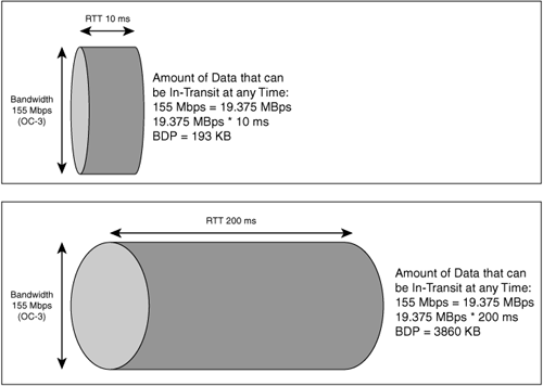
As an example, once a router transmits a packet, the router does not wait for that packet to reach its destination before the router sends another packet that is waiting in the queue. In this way, the links between network nodes (that is, routers and switches) are, when utilized, always holding some amount of data from conversations that are occurring. The network has some amount of capacity, which equates to the amount of data that can be in flight over a circuit at any given time that has not yet reached its intended destination or otherwise been acknowledged. This capacity is called the bandwidth delay product (BDP).
The BDP of a network is easily calculated. Simply convert the network data rate (in bits) to bytes (remember there is a necessary conversion from power of 10 to power of 2). Then, multiply the network data rate (in bytes) by the delay of the network (in seconds). The resultant value is the amount of data that can be in flight over a given network at any point in time. The greater the distance (latency) and the greater the bandwidth of the network, the more data that can be in flight across that link at any point in time. Figure 6-10 shows a comparison between a high BDP network and a low BDP network.
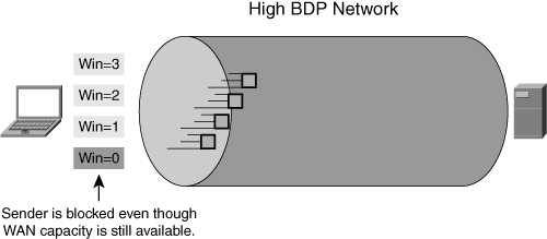
The challenge with LFNs is not that they have a high BDP, but that the nodes exchanging data over the network do not have buffers or window sizes large enough to adequately utilize the available link capacity. With multiple concurrent connections, the link can certainly be utilized effectively, but a single connection has a difficult time taking advantage of (or simply cannot take advantage of) the large amount of network capacity available because of the lack of buffer space and TCP window capacity.
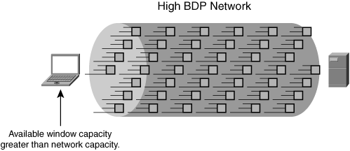
In situations where a single pair of nodes with inadequate buffer or window capacity is exchanging data, the sending node is easily able to exhaust the available window because of the amount of time taken to get an acknowledgment back from the recipient. Buffer exhaustion is especially profound in situations where the window size negotiated between the two nodes is small, because this can result in sporadic network utilization (burstiness) and periods of underutilization (due to buffer exhaustion). Figure 6-11 shows how window exhaustion leads to a node’s inability to fully utilize available WAN capacity.
Bandwidth scalability is a term that is often used when defining an optimization capability within an accelerator or configuration change that provides the functionality necessary for a pair of communicating nodes to take better advantage of the available bandwidth capacity. This is also known as fill-the-pipe optimization, which allows nodes communicating over an LFN to achieve higher levels of throughput, thereby overcoming issues with buffer or window exhaustion. This type of optimization can be implemented rather painlessly on a pair of end nodes (which requires configuration changes to each node where this type of optimization is desired, which can be difficult to implement on a global scale), or it can be implemented in an accelerator, which does not require any of the end nodes to undergo a change in configuration.
Two primary methods are available to enable fill-the-pipe optimization:
Window scaling
Scalable TCP implementation
The following sections describe both.
Window scaling is an extension to TCP (see RFC 1323, “TCP Extensions for High Performance”). Window scaling, which is a TCP option that is negotiated during connection establishment, allows two communicating nodes to go beyond the 16-bit limit (65,536 bytes) for defining the available window size.
With window scaling enabled, an option is defined with a parameter advertised that is known as the window scale factor. The window scale factor dictates a binary shift of the value of the 16-bit advertised TCP window, thereby providing a multiplier effect on the advertised window. For instance, if the advertised TCP window is 1111 1111 1111 1111 (that is, decimal 64 KB) and the window scale factor is set to 2, the binary value of the window size will have two bits added to the end of it, which would then become 11 1111 1111 1111 1111. The advertised 64-KB window size would be handled by the end nodes as a 256-KB window size.
Larger scaled windows cause the end nodes to allocate more memory to TCP buffering, which means in effect that more data can be in flight and unacknowledged at any given time. Having more data in flight minimizes the opportunity for buffer exhaustion, which allows the conversing nodes to better leverage the available network capacity. The window scale TCP option (based on RFC 1323) allows for window sizes up to 1 GB (the scale factor is set to a value of 14). Figure 6-12 shows how window scaling allows nodes to better utilize available network capacity.
The second method of enabling fill-the-pipe optimization that is available, but more difficult to implement in networks containing devices of mixed operating systems, is to use a more purpose-built and scalable TCP implementation. Many researchers, universities, and technology companies have spent a significant amount of money and time to rigorously design, test, and implement these advanced TCP stacks. One common theme exists across the majority of the implementations: each is designed to overcome performance limitations of TCP in WAN environments and high-speed environments while improving bandwidth scalability. Many of these advanced TCP stacks include functionality that helps enable bandwidth scalability and overcome other challenges related to loss and latency.
Although difficult to implement in a heterogeneous network of workstations and servers, most accelerator solutions provide an advanced TCP stack natively as part of an underlying TCP proxy architecture (discussed later in this chapter, in the “Accelerator TCP Proxy Functionality” section), thereby mitigating the need to make time-consuming and questionable configuration changes to the network end nodes. Several of the more common (and popular) implementations will be discussed later in the chapter.
The next section looks at performance challenges of TCP related to packet loss.
Packet loss occurs in any network and, interestingly enough, occurs most commonly outside of the network and within the host buffers. TCP has been designed in such a way that it can adapt when packet loss is encountered and recover from such situations. Packet loss is not always bad. For instance, when detected by TCP (segments in the retransmission queue encounter an expired timer, for instance), packet loss signals that the network characteristics may have changed (for example, if the available bandwidth capacity decreased). Packet loss could also signal that there is congestion on the network in the form of other nodes trying to consume or share the available bandwidth. This information allows TCP to react in such a way that allows other nodes to acquire their fair share of bandwidth on the network, a feature otherwise known as fairness.
Fairness is defined as a trait exhibited by networks that allow connections to evenly share available bandwidth capacity. TCP is considered to be a transport protocol that can generally ensure fairness, because it adapts to changes in network conditions, including packet loss and congestion, which are commonly encountered when flows compete for available bandwidth.
The result of packet loss in connection-oriented, guaranteed-delivery transport protocols such as TCP is a shift in the transmission characteristics to ensure that throughput is decreased to allow others to consume available capacity and also to accommodate potential changes in network capacity. This shift in transmission characteristics (in the case of TCP, decreasing the cwnd) could have a detrimental impact on the overall throughput if the cwnd available drops to a level that prevents the node from fully utilizing the network capacity.
Standard TCP implementations will drop cwnd by 50 percent when a loss of a segment is detected. In many cases, dropping cwnd by 50 percent will not have an adverse effect on throughput. In some cases, however, where the BDP of the network is relatively high, decreasing cwnd by 50 percent can have a noticeable impact on the throughput of an application.
TCP is designed to be overly conservative in that it will do its best to provide fairness across multiple contenders. This conservative nature is rooted in the fact that TCP was designed at a time when the amount of bandwidth available was far less than what exists today. The reality is that TCP needs to be able to provide fairness across concurrent connections (which it does), adaptive behavior for lossy networks (which it does), and efficient utilization of WAN resources (which it does not). Furthermore, when a loss of a packet is detected, all of the segments within the sliding window must be retransmitted from the retransmission queue, which proves very inefficient in WAN environments. Figure 6-13 shows the impact of packet loss on the TCP congestion window, which may lead to a decrease in application throughput.
When TCP detects the loss of a segment, cwnd is dropped by 50 percent, which effectively limits the amount of data the transmitting node can have outstanding in the network at any given time. Given that standard TCP congestion avoidance uses a linear increase of one segment per successful round trip, it can take quite a long time before the cwnd returns to a level that is sufficient to sustain high levels of throughput for the application that experienced the loss. In this way, TCP is overly conservative and packet loss may cause a substantial impact on application throughput, especially given that bandwidth availability is far greater than it was 20 years ago.
Overcoming the impact of packet loss through the use of TCP extensions in a node or by leveraging functionality in an accelerator can provide nearly immediate improvements in application throughput. Making such changes to each end node may prove to be an administrative nightmare, whereas deploying accelerators that provide the same capability (among many others) is relatively simple. There are three primary means of overcoming the impact of packet loss:
Selective acknowledgment (SACK)
Forward error correction (FEC)
Advanced congestion avoidance algorithms
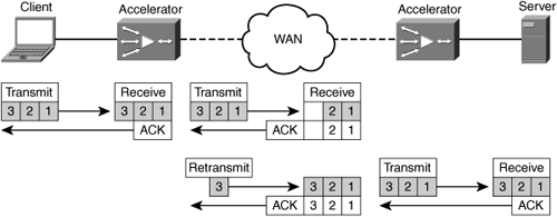
By employing SACK, acknowledgments can be sent to notify the transmitter of the specific blocks of data that have been received into the receiver’s socket buffer. Upon detecting loss, the transmitting node can then resend the blocks that were not acknowledged rather than send the contents of the entire window. Figure 6-14 shows how an accelerator acting as a TCP proxy (discussed later, in the section “Accelerator TCP Proxy Functionality”) can provide SACK to improve efficiency in retransmission upon detecting the loss of a segment.
FEC is used to generate parity packets that allow the receiving node to recover the data from a lost packet based on parity information contained within the parity packets. FEC is primarily useful in moderately lossy networks (generally between .25 and 1 percent loss). Below this loss boundary, FEC may consume excessive amounts of unnecessary bandwidth (little return on bandwidth investment because the loss rate is not substantial). Above this loss boundary, FEC is largely ineffective compared to the total amount of loss (not enough parity data being sent to adequately re-create the lost packets) and therefore consumes excessive CPU cycles on the transmitting and receiving nodes or accelerators with little to no performance benefit.
Advanced TCP implementations generally decrease cwnd less aggressively upon encountering packet loss and use more aggressive congestion avoidance algorithms to better utilize network capacity and more quickly return to previous levels of throughput after encountering packet loss. This yields a smaller drop in cwnd and faster increase in cwnd after encountering packet loss, which helps to circumvent performance and throughput challenges. Advanced TCP stacks are discussed in the next section.
The previous sections have outlined some of the limitations that TCP imposes upon application performance. Many universities and companies have conducted research and development to find and develop ways to improve the behavior of TCP (or completely replace it) to improve performance and make it more applicable to today’s enterprise and Internet network environments. The result of this research and development generally comes in one of two forms: an extension to TCP (commonly applied as a negotiated option between two nodes that support the extension) or an alternative stack that is used as a replacement for TCP. For instance, SACK is an extension to TCP and is enabled based on negotiation during connection establishment. Advanced stacks, such as Binary Increase Congestion TCP (BIC-TCP), High Speed TCP (HS-TCP), Scalable TCP (S-TCP), and others, are an alternative to TCP extensions and generally require that the peer nodes be running the same TCP implementation to leverage the advanced capabilities.
Accelerator devices commonly use an advanced TCP implementation, which circumvents the need to replace the TCP stack on each node in the network. When considering an implementation with an advanced TCP stack, it is important to consider three key characteristics of the implementation:
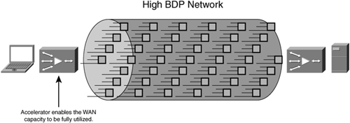
Bandwidth scalability: The ability to fully utilize available WAN capacity, otherwise known as fill-the-pipe. Figure 6-15 shows how fill-the-pipe optimizations such as window scaling can be employed in an accelerator to achieve better utilization of existing network capacity.
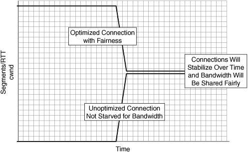
TCP friendliness: The ability to share available network capacity fairly with other transmitting nodes that may not be using the same advanced TCP implementation. This is another form of fairness, in that the optimized connections should be able to share bandwidth fairly with other connections on the network. Over time, the bandwidth allocated to optimized and unoptimized connections should converge such that resources are shared across connections.
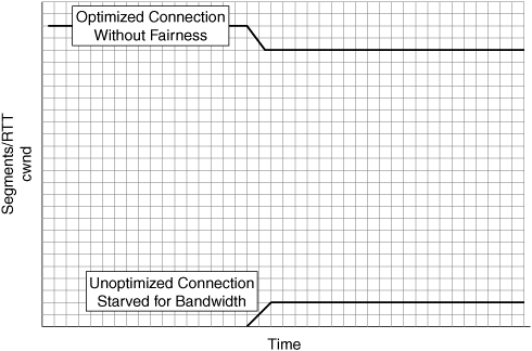
Figure 6-16 shows the impact of using accelerators that provide TCP optimization that is not friendly to other nonoptimized connections, which can lead to bandwidth starvation and other performance challenges. Figure 6-17 shows how accelerators that provide TCP optimization that is friendly to other nonoptimized connections will compete fairly for network bandwidth and stabilize with other nonoptimized connections.
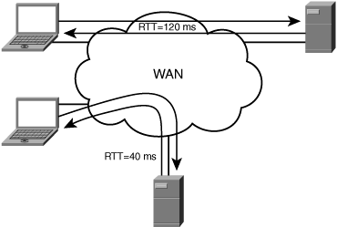
Roundtrip time (RTT) fairness: The ability to share bandwidth fairly across connections even if the RTT between the two communicating node pairs is unequal. RTT fairness is another component of fairness at large.
With RTT disparity, the nodes that are closer to one another can generally consume a larger portion of available WAN bandwidth capacity than the nodes that are more distant when sharing bandwidth. This is due to the way TCP congestion avoidance relies on acknowledgment messages to increment the cwnd, which increases the amount of data that can be outstanding in the network. This leads to the two nodes that are closer to one another being able to transmit data more quickly because acknowledgments are received more quickly and the congestion window is advanced more rapidly. Figure 6-18 shows an example of a network of nodes where RTT disparity is present.
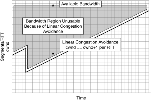
These advanced TCP implementations commonly implement an advanced congestion avoidance algorithm that overcomes the performance challenge of using a conservative linear search such as found in TCP. With a conservative linear search (increment cwnd by one segment per successful RTT), it may take a significant amount of time before the cwnd increments to a level high enough to allow for substantial utilization of the network. Figure 6-19 shows how TCP’s linear search congestion avoidance algorithm leads to the inability of a connection to quickly utilize available network capacity (lack of aggressiveness).
This section examines some of the advanced TCP implementations and characteristics of each but is not intended to be an exhaustive study of each or all of the available implementations.
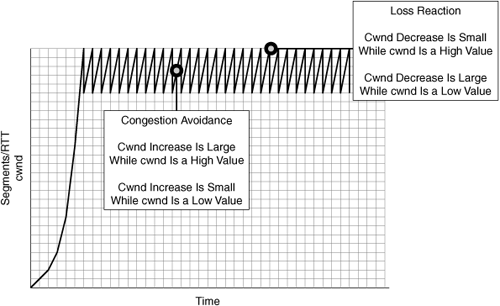
High-Speed TCP (HS-TCP) is an advanced TCP implementation that was developed primarily to address bandwidth scalability. HS-TCP uses an adaptive cwnd increase that is based on the current cwnd value of the connection. When the cwnd value is large, HS-TCP uses a larger cwnd increase when a segment is successfully acknowledged. In effect, this helps HS-TCP to more quickly find the available bandwidth, which leads to higher levels of throughput on large networks much more quickly.
HS-TCP also uses an adaptive cwnd decrease based on the current cwnd value. When the cwnd value for a connection is large, HS-TCP uses a very small decrease to the connection’s cwnd value when loss of a segment is detected. In this way, HS-TCP allows a connection to remain at very high levels of throughput even in the presence of packet loss but can also lead to longer stabilization of TCP throughput when other, non-HS-TCP connections are contending for available network capacity. The aggressive cwnd handling of HS-TCP can lead to a lack of fairness when non-HS-TCP flows are competing for available network bandwidth. Over time, non-HS-TCP flows can stabilize with HS-TCP flows, but this period of time may be extended due to the aggressive behavior of HS-TCP.
HS-TCP also does not provide fairness in environments where there is RTT disparity between communicating nodes, again due to the aggressive handling of cwnd. This means that when using HS-TCP, nodes that are communicating over shorter distances will be able to starve other nodes that are communicating over longer distances due to the aggressive handling of cwnd. In this way, HS-TCP is a good fit for environments with high bandwidth where the network links are dedicated to a pair of nodes communicating using HS-TCP as a transport protocol but may not be a good fit for environments where a mix of TCP implementations or shared infrastructure is required. Figure 6-20 shows the aggressive cwnd handling characteristics displayed by HS-TCP.
You can find more information on HS-TCP at http://www.icir.org/floyd/hstcp.html
Scalable TCP (S-TCP) is similar to HS-TCP in that it uses an adaptive increase to cwnd. S-TCP will increase cwnd by a value of (cwnd × .01) when increasing the congestion window, which means the increment is large when cwnd is large and the increment is small when cwnd is small.
Rather than use an adaptive decrease in cwnd, S-TCP will decrease cwnd by 12.5 percent (1/8) upon encountering a loss of a segment. In this way, S-TCP is more TCP friendly than HS-TCP in high-bandwidth environments. Like HS-TCP, S-TCP is not fair among flows where an RTT disparity exists due to the overly aggressive cwnd handling.
You can find more information on S-TCP at http://www.deneholme.net/tom/scalable/.
Binary Increase Congestion TCP (BIC-TCP) is an advanced TCP stack that uses a more adaptive increase than that used by HS-TCP and S-TCP. HS-TCP and S-TCP use a variable increment to cwnd directly based on the value of cwnd. BIC-TCP uses connection loss history to adjust the behavior of congestion avoidance to provide fairness.
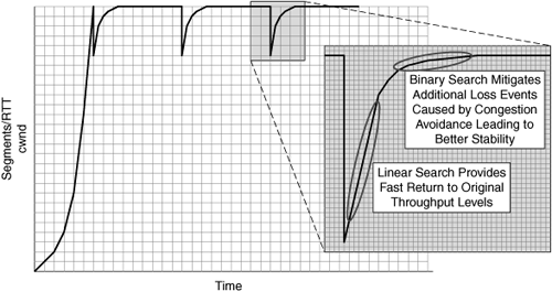
BIC-TCP’s congestion avoidance algorithm uses two search modes—linear search and binary search—as compared to the single search mode (linear or linear relative to cwnd) provided by standard TCP, HS-TCP, and S-TCP. These two search modes allow BIC-TCP to adequately maintain bandwidth scalability and fairness while also avoiding additional levels of packet loss caused by excessive cwnd aggressiveness:
Linear search: Uses a calculation of the difference between the current cwnd and the previous cwnd prior to the loss event to determine the rate of linear search.
Binary search: Used as congestion avoidance approaches the previous cwnd value prior to the loss event. This allows BIC-TCP to mitigate additional loss events caused by the connection exceeding available network capacity after a packet loss event.
The linear search provides aggressive handling to ensure a rapid return to previous levels of throughput, while the binary search not only helps to minimize an additional loss event, but also helps to improve fairness for environments with RTT disparity (that is, two nodes exchanging data are closer than two other nodes that are exchanging data) in that it allows convergence of TCP throughput across connections much more fairly and quickly.
Figure 6-21 shows how BIC-TCP provides fast returns to previous throughput levels while avoiding additional packet loss events.
For more information on BIC-TCP, visit http://www.csc.ncsu.edu/faculty/rhee/export/bitcp/index.htm
Note
Other advanced TCP implementations exist, including Additive Increase Multiplicative Decrease (AIMD), Fast AQM Scalable TCP (FAST), and Simple Available Bandwidth Utilization Library (SABUL). Because the focus of this book is on the advanced TCP implementations commonly found in accelerator devices, we will not discuss these additional implementations.
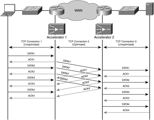
Most accelerator devices provide proxy functionality for TCP. This allows enterprise organizations to deploy technology that overcomes WAN conditions without having to make significant changes to the existing clients and servers on the network. In effect, a TCP proxy allows the accelerator to terminate TCP connections locally and take ownership of providing guaranteed delivery on behalf of the communicating nodes. With a TCP proxy, the accelerator manages local TCP transmit and receive buffers and provides TCP-layer acknowledgments and window management. This also allows the accelerator to effectively shield communicating nodes from packet loss and other congestion events that occur in the WAN.
Before this type of function can be employed, accelerator devices must either automatically discover one another or have preconfigured knowledge of who the peer device is. This allows existing clients and servers to retain their existing configurations and TCP implementations, and allows the accelerator devices to use an advanced TCP stack between one another for connections between communicating nodes that are being optimized. The optimized connections between accelerator devices may also be receiving additional levels of optimization through other means such as compression (discussed later, in the section “Accelerators and Compression”), caching, read-ahead, and others as described in Chapters 4 and 5.
Accelerators that use a TCP proxy terminate TCP locally on the LAN segment it is connected to and use optimized TCP connections to peer accelerators over the WAN. By acting as an intermediary TCP proxy device, an accelerator is uniquely positioned to take ownership of managing WAN conditions and changes on behalf of the communicating nodes. For instance, if an accelerator detects the loss of a packet that has been transmitted for an optimized connection, the accelerator retransmits that segment on behalf of the original node. This stops any WAN conditions from directly impacting the end nodes involved in the conversation that is being optimized by the accelerators, assuming the data remains in the socket buffers within the accelerator. The accelerator provides acceleration and throughput improvements to clients and servers with legacy TCP stacks, creating near-LAN TCP behavior while managing the connections over the WAN.
Figure 6-22 shows how accelerators can act as a proxy for TCP traffic, which shields LAN-attached nodes from WAN conditions.
By employing accelerators in the network that provide TCP proxy functionality, clients and servers communicating over the WAN experience better performance and loss recovery. First, loss events occurring in the WAN are wholly contained and managed by the accelerators. Second, acknowledgments are handled locally by the accelerator, thereby allowing the clients and servers to achieve potentially very high levels of throughput.
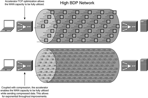
When a connection is further optimized through advanced compression (as discussed later in this chapter), not only are clients and servers able to fill the pipe, but accelerators are able to fill the pipe with compressed data (or redundancy-eliminated data), which yields exponentially higher levels of throughput in many situations. Figure 6-23 shows how accelerator-based TCP optimization can be leveraged in conjunction with advanced compression (discussed later in the chapter) to fill the pipe with compressed data, providing potentially exponential throughput increases.
A good accelerator solution will include the TCP optimization components discussed earlier in this chapter and application acceleration capabilities discussed in Chapters 4 and 5, along with the compression techniques discussed in the next section. All of these factors combined can help improve efficiency and application performance over the WAN.
TCP optimization and advanced TCP implementations are useful to help ensure that the network resources are adequately and efficiently utilized. However, the WAN can still be a bottleneck from a performance perspective especially when considering the massive amount of bandwidth disparity that exists between the LAN and the WAN. The most common response to addressing this bandwidth disparity is to simply add more bandwidth.
There is a severe disparity in terms of available bandwidth capacity when comparing the LAN and the WAN, and a growing disparity in terms of the cost per bit of service between the two. Yet another disparity exists between the tremendous amount of latency found in WAN connections compared to the latency found in a LAN. Put simply, the cost per bit/second of low-latency LAN bandwidth is decreasing at a faster rate than is the cost per bit/second of high-latency WAN bandwidth, making it dramatically more expensive to upgrade WAN capacity than it is to upgrade LAN capacity. This problem is exacerbated when factoring in the additional service and capital expenditures that accompany a WAN upgrade.
With this in mind, many organizations are looking to accelerator solutions to bridge the divide between WAN bandwidth and performance, and most are finding that implementing accelerator solutions (which address more than just bandwidth concerns) costs far less from a total cost of ownership (TCO) perspective and provides a massive return on investment (ROI) because it [implementing accelerator solutions] enables infrastructure to be consolidated and improves productivity and collaboration.
Compression is a technology that helps to minimize the amount of bandwidth consumed by data in transit over a network and is not a new technology. Advanced compression algorithms and implementations have come about that are more effective and efficient than the simple compression algorithms that have been around for years.
This section examines compression at a high level, including the difference between per-packet implementations and flow-based compression implementations, and then provides a more detailed overview of advanced compression techniques such as data suppression. Advanced compression techniques not only compress data in flight but also reduce the frequency of the transfer of redundant data patterns. Most accelerator devices today provide some form of compression and, when coupled with TCP optimization and application acceleration, not only can improve application performance significantly, but can do so while minimizing the amount of network bandwidth required.
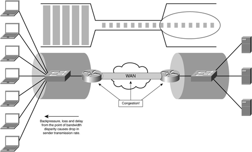
The key challenge for lower-bandwidth networks (or any WAN where there is a high amount of contention for available bandwidth) is that the device managing bandwidth disparity (that is, the router) has to negotiate traffic from a very high-speed network onto a very low-speed network. In terms of how TCP interacts with this disparity, data is sent at the rate determined by the available cwnd, and when a bandwidth disparity is present, the ingress interface queues on the router begin to fill, causing delay to a point where loss is encountered. The detection of this loss results in a decrease of the cwnd, and the transmitting node, while in congestion avoidance, attempts to stabilize at a rate that is conducive to transmission without (or nearly without) loss.
In effect, the overloaded queue (or loss in the WAN, or anything that causes loss or delay of acknowledgment) helps stimulate the transmitting node into finding the right level at which to send data. When the router receives packets into its queues, it drains the ingress queues at a rate determined by the available next-hop network capacity and any applicable QoS configuration.
The problem begins to unfold as the client is able to transmit data at a far faster pace than the router is able to forward onto the lower-bandwidth network. This results in a trickle effect whereby only a small amount of data is able to traverse the lower-bandwidth network at a given time, and ultimately the transmitting node will adjust its throughput characteristics to match this rate based on TCP congestion avoidance. This trickle of data is routed through the network and may encounter several other points of congestion and loss along the way, all of which can directly impact the transmission rate of the sender.
When the data is finally placed on the LAN at the distant location, the receiving node ultimately has the impression that it is dealing with a very slow sender. This is directly caused by the bandwidth disparity found in the network. Conversely, in the return direction, when the server is responding to the client, the same issues are encountered, thus leading both nodes to believe that the other is slow to transmit.
Figure 6-24 shows the bandwidth disparity between the LAN and the WAN and how TCP rate control stabilizes transmitter throughput to the minimum available end-to-end network capacity.
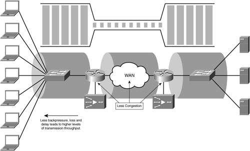
With accelerators in place and providing compression, bandwidth disparity is largely mitigated. In effect, through compression the accelerator is able to shrink the amount of data being sent across the network to minimize bandwidth consumption, and decompress the data to its original state on the other end of the network. This not only results in bandwidth savings over the WAN, but also helps to ensure that a larger amount of data can be found in the LAN. From the perspective of the client and the server, less congestion is encountered, thereby allowing them to send at higher rates, and improving the performance of the applications in use. Figure 6-25 shows the same implementation leveraging accelerators and how less congestion is encountered.
While numerous compression algorithms exist, this book focuses on the two types that are used most frequently in accelerator platforms: traditional data compression and data suppression. Furthermore, this chapter focuses on lossless compression, because data cannot be compromised when working with enterprise applications the way it can when viewing images, for example.
Traditional data compression is defined as the process of encoding data using fewer bits than an unencoded representation would use. This is enabled by having two devices exchanging information using a common scheme for encoding and decoding data. For instance, a person can use a popular compression utility to minimize the amount of disk space a file consumes (encoding), which in turn minimizes the amount of bandwidth consumed and time taken to e-mail that same file to another person. The person who receives the e-mail with that compressed file needs to use a utility that understands the compression algorithm to decode the data to its original form. This again relies on the assumption that the sender and receiver have explicit knowledge about how to encode and decode the data in the same way.
Data compression can be applied in the network between accelerators assuming that both accelerators are designed to be compatible with one another and have a fundamental understanding of the compression algorithms employed. Most accelerators implement a well-known type of compression algorithm, such as Lempel-Ziv (or one of its variants such as LZ77 or LZ78) or DEFLATE.
Many algorithms achieve compression by replacing sections of data found within the object with small references that map to a data table that contains an index of data encountered within the object and references generated for that data. Such algorithms commonly use a sliding window with a power-of-two fixed window size (such as 1 KB, 2 KB, 4 KB, 8 KB, 16 KB, 32 KB, or beyond) to scan through the object, identifying data patterns within the window and referencing with signatures that point back to the index table. In this way, compression is limited to the capacity of the sliding window, granularity of the patterns that are identified, and the data table structures that maintain the mapping between signatures and data structures that have been previously seen. The limit of how effective the compression itself can be is called the compression domain.
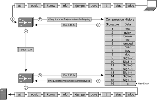
Data suppression operates in a similar fashion to standard data compression. Unlike data compression, however, data suppression is designed to leverage a massive compression domain that extends beyond the object, packet, or session being examined. In a sense, data compression is limited to the object, packet, or session being transmitted, whereas data suppression can leverage a larger, longer-lived compression history that is specific to previous patterns seen between two accelerator devices.
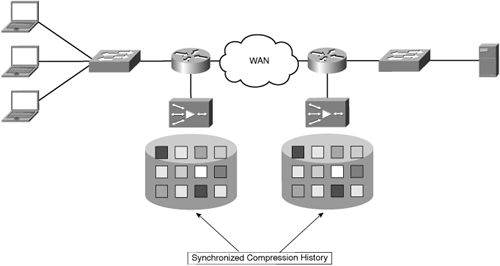
Data suppression assumes that each accelerator has a storage repository that is used as a compression history. Data suppression requires that this storage repository, sometimes known as a “codebook” or “dictionary,” be loosely synchronized between two accelerators that wish to provide data suppression capabilities. Some accelerators implement data suppression using memory as a storage repository for compression history. Memory-only data suppression provides high-performance I/O for compressing and decompressing data, but has a limited capacity in terms of compression history. Some accelerators use hard disk drives instead of memory, a technique that has lower I/O performance than memory-only data suppression, but has a much larger compression history capacity. Many of today’s accelerators leverage a combination of both disk and memory to achieve high performance without compromising on the length of compression history for their data suppression algorithms.
Figure 6-26 shows an example of two accelerators, each deployed in separate locations, with a synchronized compression history.
Much like data compression, most data suppression algorithms use a sliding window to identify previously seen data patterns from within packets or connections. Each unique data pattern that is identified is assigned a unique signature, which is a small representation of the original data, or a reference to the entry in the compression library where the original data resides. Most signatures are typically only a few bytes in size. Given that a relatively large amount of data can be referenced by a signature that is only a few bytes in size, it is common for data suppression to be able to achieve over 1000:1 compression for a fully redundant data segment and up to 50:1 or better compression for an entire flow.
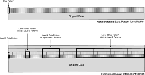
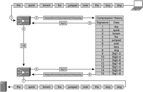
Many of the data suppression implementations available in accelerators today do not use a simple single-level data pattern identification process; rather, most use a hierarchical means of identifying data patterns. A hierarchical data pattern identification process analyzes a block of data at multiple layers. With hierarchical data pattern recognition, the accelerator is able to not only create signatures for the most basic data patterns, but also formulate additional signatures that refer to a large number of data patterns or signatures. In this way, if a greater degree of redundancy is identified within the data patterns, hierarchical data pattern recognition allows a smaller number of signatures to be used to refer to the original data being transmitted. If hierarchical data pattern recognition is not being used, one signature is required for each repeated data pattern, which may prove less efficient.
Hierarchical data pattern matching can yield far higher levels of data suppression (compression) than data pattern matching functions that are nonhierarchical. Figure 6-27 shows the difference between hierarchical and nonhierarchical data pattern recognition algorithms.
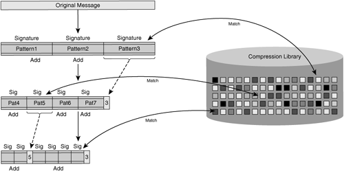
During the process of data pattern matching, a signature is generated for each identified data pattern being transmitted, and in the case of hierarchical data pattern recognition, signatures may also be generated that identify a large number of data patterns or signatures. Once the signatures have been generated, the accelerator then begins to perform a pattern-matching function whereby it compares the signature of the identified patterns (generally starting with the largest data patterns when hierarchical data pattern matching is employed) with the contents of the local compression library. This local compression library contains a database containing signatures and data patterns that have been previously recognized by the two peering accelerators, and can be built dynamically (as data is handled during the normal course of network operation) or proactively (using a cache-warming or preposition type of feature before the first user transmission is ever received).
As repeated data patterns are identified, they are removed from the message, and only the signature remains. This signature is an instruction for the distant device, notifying it of what data to retrieve from its compression history to replace the original data pattern back into the flow.
For data patterns that are nonredundant (no entry exists in the compression library for the signature), the new signature and data pattern are added to the local compression library. In this case, the newly generated signatures and data pattern are sent across the network to notify the distant accelerator that it needs to update its compression library with this new information.
Figure 6-28 shows the top-down data pattern matching function applied by an encoding accelerator when leveraging data suppression.
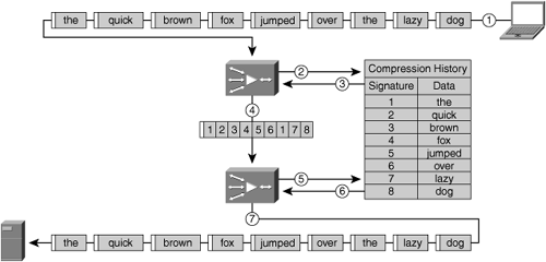
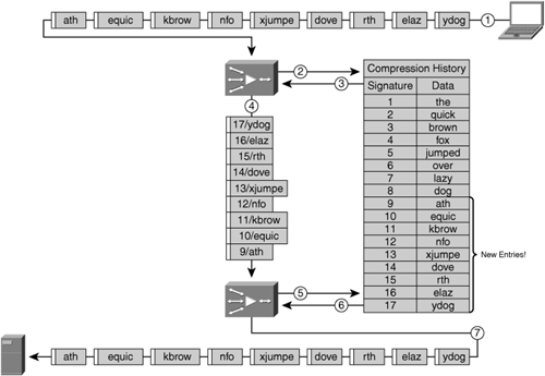
This entire process of suppressing data into a redundancy-eliminated message is defined as encoding. When peering accelerators are able to perform data suppression, the only data that needs to traverse the network is the encoded message, which includes signatures to previously seen data segments and data segments (with newly generated signatures) for data that has not been seen before, or otherwise does not exist in the local compression library.
Additionally, accelerators commonly implement data integrity protection mechanisms to ensure that the rebuild of an encoded message by the recipient accelerator is done without compromising the integrity of the original message. This commonly includes a hash calculation of the original message, called a message validity signature, immediately before encoding begins. In most cases, the hash calculation to generate the message validity signature includes accelerator-specific keys in the calculation or other means of ensuring that hash collisions cannot occur. Figure 6-29 shows an example of what an encoded message sent among accelerators may look like.
When an encoded message is received, the message validity signature attached to the encoded message is stripped and placed to the side. The remaining message contains signatures without data attached (for redundant data patterns that should exist in the compression library) and signatures with data attached (nonredundant data), which the accelerator should add to its compression library.
The receiving accelerator then begins the process of decoding, whereby the original message is rebuilt. This is done by replacing each signature sent without attached data with the data pattern that is identified by that signature within the local compression context. Any data pattern that has an accompanying signature is added to the local compression library and the signature is stripped from the encoded message. If any signatures is identified that was generated out of the process of hierarchical pattern matching, each of the data patterns referenced by the signature is extracted from the local compression library and put in place of the signature in the encoded message.
Once the accelerator has fully decoded the encoded message, it then generates a new message validity signature, that is, the same hash calculation using the same parameters such as accelerator-specific keys or other factors, and compares the newly generated message validity signature with the message validity signature that was supplied in the encoded message by the encoding accelerator. If the two align, the decoding accelerator then knows that the message was rebuilt with data validity and integrity guaranteed, and the decoded message can then be forwarded to its destination. If any signature referenced in the encoded message does not appear in the local compression library, the decoding accelerator can send a nonacknowledgment message to the encoder to notify the encoder that the data does not exist, thereby forcing a retransmission of the data associated with the signature that does not appear in the decoding accelerator’s compression history.
Data suppression also works closely with traditional data compression in accelerators. The signatures and message validity signatures generated by the data suppression function are commonly compressible, meaning that additional layers of compression can be found above and beyond the level of compression provided by data suppression on its own. Data suppression compression libraries are generally peer-specific, and some implementations can share libraries across peers. Given that the compression library for data suppression is far larger than it is for data compression and is not tied to a packet, session, or object, it can be far more effective at freeing up available WAN capacity, and can generally be efficient in reducing redundancy even across multiple applications.
Because data suppression is commonly implemented as a WAN optimization component in the network or transport layer, it does not discriminate among applications (for example, downloading an object from a website could populate the compression library to provide significant compression for an e-mail upload with that same, or modified, object). Furthermore, a data pattern that is not deemed to be a repeated pattern can also be sent through the data compression library, which means that even though a data pattern is being seen for the first time, it may be compressible, meaning that less bandwidth is used even for those scenarios.
When deploying accelerators, a best practice is to ensure that enough storage capacity is allocated to provide at least one week’s worth of compression history. For instance, if a branch office location is connected to the corporate network via a T1 line (1.544 Mbps), the amount of disk capacity necessary to support that location from a compression history perspective could be calculated. If the T1 line were utilized at a rate of 75 percent for 50 percent of each day per week, the raw compression history requirement for one week would equate to the following:
Convert 1.544 Mbps to bytes (1.544 Mbps is approximately 192 kBps)
192 kBps × 60 = 11.52 MB/minute
11.52 MB/minute × 60 = 69.12 MB/hour
69.12 MB/hour × 24 = 16.59 GB/day
16.59 GB/day × .75 × .50 = 6.2 GB/week
Assuming that the data traversing the link from the branch office back to the corporate network is 75 percent redundant (which is conservative in most branch office scenarios), this equates to a requirement of around 1.5 GB/week of compression history required to support this particular branch office location. One week of compression history generally provides enough compression data to optimize not only immediately interactive user access requirements, but also scenarios where a user begins interacting with a working set of data that has not been touched in up to a week. This also provides sufficient coverage for multiuser scenarios—for instance, where everyone in a remote office receives an e-mail with the same attachment, even if the transmission of that e-mail happens days later.
Most accelerators implement both data suppression and traditional data compression functions. This section examines two commonly found implementations: per-packet compression and session-based compression. This section also discusses directionality as it relates to the accelerator’s compression library.
Per-packet compression treats each packet as a compression domain. This means that each packet is analyzed as an autonomous object and compressed as an autonomous object. With such an architecture, each packet that is received by an accelerator must be handled individually.
Given that packet sizes are largely limited by the data link layer being traversed, it is safe to assume that the compression domain for per-packet compression is generally 200 to 1500 bytes (but can certainly be larger or smaller). Given this limitation, most accelerators that implement per-packet compression also implement some form of data suppression to increase the compression history, which allows larger repeatable sequences to be identified, thus providing better compression and higher degrees of bandwidth savings. However, because the accelerator processes each packet individually, it does not have the opportunity to examine a larger amount of data, precluding it from providing higher levels of compression. Per-packet processing also creates sensitivities to data changes, which are more difficult to detect and isolate when the window of data being reduced is limited to the size of a packet.
Figure 6-30 shows how per-packet compression would be used on a fully redundant transmission of the same set of packets. In this figure, the packet stream being sent is fully redundant. The process shown in this figure follows:
A stream of data is sent as a series of packets.
The accelerator compares the contents of each packet against the compression history.
Redundancy is eliminated and redundant segments are replaced by signatures.
The compressed packet is sent across the network and intercepted by the distant accelerator.
The distant accelerator compares the contents of the encoded packet with the compression history.
The distant accelerator replaces signatures with data patterns from the compression history.
The distant accelerator repacketizes and reframes the original data and forwards it to the intended destination.
The challenge with per-packet compression lies in the ability of an accelerator to identify repeated data patterns that are directly associated with the position of the data pattern within the packet being received. Therefore, such forms of compression can be challenged when attempting to compress packets received from the transmission of a previously seen set of data when that set of data has undergone slight modification. The challenge is that repeated patterns are not located in the same position within the subsequently received packets after changes have been applied to the data as compared to the position where the original data was found. In this way, data does not have the same locality to the packet boundaries as it did before the changes were applied.
In these situations, the compression history must be augmented with the new data on both devices, which means the first transmission of the changed data can be largely considered nonredundant and, therefore, only minimal amounts of compression can be applied. The compression history from the original transfer of the data is mostly unusable in this case, which leads to excessive and inefficient use of memory and disk capacity for compression history on both accelerator devices to store the new data and the original patterns.
Figure 6-31 highlights the challenges of per-packet compression when data has been changed, causing a large number of new compression library entries to be created and thereby producing minimal compression benefits. This example shows the impact of adding the letter a to the beginning of the sentence used in Figure 6-30. Notice that a large number of new entries need to be added to the compression history, and little to no bandwidth savings are realized.
An alternative to per-packet compression, which generally provides higher levels of compression even under significant amounts of data change, is session-based compression, also known as persistent compression. Session-based compression provides two key functions:
The ability to leverage a compression history that extends through the life of the entire TCP connection when employing traditional data compression algorithms such as LZ or DEFLATE
The ability to extend the compression domain for data suppression functionality by leveraging a TCP proxy as an intermediary data buffer
Extending the compression library to span the history of the TCP connection provides better overall compression because the history that can be leveraged is far greater than and not limited to the packet size.
Using the TCP proxy as an intermediary data buffer allows the accelerator to temporarily buffer a large amount of data that can then be delivered en masse to the data suppression function, which allows it to span boundaries of multiple packets when identifying redundancy. By disconnecting the data suppression function and the data from the packet boundaries, data suppression algorithms are able to better identify redundancy and isolate changes to previously encountered byte patterns. This allows for far higher levels of compression than can be provided with per-packet compression.
Figure 6-32 shows how session-based compression with hierarchical data suppression provides location-independent compression capabilities with high levels of compression. Notice how the hierarchical compression history contains signatures that reference a series of other signatures, thereby providing higher levels of compression. In this figure, a single signature represents the entire string of text being sent.
When coupled with a data suppression function that uses a content-based means of identifying data patterns and hierarchical pattern matching, this allows the data suppression function to accurately pinpoint where changes were inserted into the data stream. In essence, when changes are made to the data and the changed data is transmitted between two nodes, content-based pattern matching can isolate the new data to allow the previously built compression library entries to still be leveraged, resulting in high levels of compression even in the face of changed data. Rather than having to re-update the entire compression library on both devices, the accelerators can incrementally update the compression libraries with only the new data. This means that the challenges that plague per-packet compression are nullified.
Figure 6-33 shows that session-based compression with hierarchical data suppression capabilities provides far better identification of changed byte patterns than do per-packet compression algorithms, resulting in more efficient use of the compression library, bandwidth savings, and overall better performance.
Another subtle architectural implementation that you should consider is the directionality of the data suppression compression library. Directionality defines whether a single compression library is used regardless of the direction of traffic flow, called a bidirectional compression library, or whether a single compression library is used per direction of traffic flow, called a unidirectional compression library.
In the case of a bidirectional compression library, traffic flowing in one direction populates the compression library, and this same library can be used for traffic flowing in the reverse direction through the accelerators. In the case of a unidirectional compression library, traffic flowing in one direction populates one compression library, and traffic flowing in the reverse direction populates a separate compression library. With unidirectional compression libraries, there must be one library per direction of traffic flow.
Having unidirectional compression libraries introduces inefficiencies and performance limitations that need to be considered. Having a unidirectional compression library–based architecture means that when a user downloads an object, only the repeated download of that object will pass through the same library, because the traffic is flowing in the same direction. Even after an object has been downloaded, the subsequent upload (in the reverse direction) of that object passes through a completely different compression library, meaning that it will not be suppressed.
The upload of the object effectively receives no benefit from the download because two separate compression libraries are used. This not only creates the issue of having poor performance until the object has been transferred in both directions, but also means lower overall efficiency from a memory and disk utilization perspective, as the data must be stored twice. Having to store the data twice leads to a lower overall compression history. Figure 6-34 highlights the performance challenges of unidirectional data suppression libraries in scenarios where data that has been downloaded is being uploaded.
With a bidirectional compression library, the problem illustrated in Figure 6-34 is not encountered. Traffic flowing in either direction leverages the same compression library, so the download of an object can be leveraged to help suppress the repeated patterns found while uploading the same object. Furthermore, repeated patterns are not stored once per direction of traffic flow, leading to better efficiency when utilizing disk and memory resources while also extending the overall effective compression history that the accelerator peers can leverage. Figure 6-35 shows how use of a bidirectional data suppression library provides compression benefits and is agnostic to the direction of traffic flow.
This chapter examined two of the key technologies that are provided in WAN optimization solutions: transport protocol optimization and compression. These techniques are commonly implemented in a cohesive accelerator architecture with other application-specific components and provide the foundation for overcoming WAN performance obstacles. By employing transport protocol optimization, available WAN capacity can be better leveraged and higher levels of performance can be sustained in lossy environments. Through advanced compression techniques, performance constraints related to capacity can be overcome to improve application performance while also minimizing the amount of bandwidth consumption.
WAN optimization, when combined with other acceleration techniques described in previous chapters and network control capabilities, helps to enable a globally distributed workforce with centralized I/T infrastructure, all while minimizing the impact to the existing network and mitigating costly capacity upgrades in many cases.
