
10 Setup Menu

Tic Tacs in a Bottle © 2019 Dave Gould (davegould68)
The Setup Menu contains a series of settings for basic camera configuration that are not directly related to taking pictures. It covers things like Monitor brightness, battery information, firmware version, the default language, Wi-Fi, Bluetooth, smart device connectivity, and many other basic settings. Here is a look at the Setup Menu location (figure 10.1).

Figure 10.1: The Setup Menu
The settings in the Setup Menu are most likely the first ones you’ll configure when you prepare your new Nikon Z6. You’ll have to set the Time zone and date, Language, and Copyright information—for embedding in the metadata of your pictures—among many other things.
Following is a list of the 34 functions available in the Setup Menu:
- Format memory card: This function allows you to delete all images from your camera’s memory card(s).
- Save user settings: You can configure the camera under the individual user settings U1, U2, and U3 on the Mode dial and save the settings to internal memory. The Z6 will remember the settings and reload them when you select U1, U2, or U3.
- Reset user settings: If you want to return one of your user settings (U1, U2, or U3) to the factory default, this function will do it for you.
- Language: Choose the language you would like your camera to use from a list of four languages (firmware C2.00). Menus and screens will be displayed in the chosen language.
- Time zone and date: Set the Time zone, Date and time, Date format, and Daylight saving time in your camera.
- Monitor brightness: Choose the brightness level for the Monitor on the back of your camera.
- Monitor color balance: Select the color balance of the Monitor. You can use a reference shot taken by the camera, such as a picture of a color chart, to calibrate the Monitor’s color balance.
- Viewfinder brightness: Use this to set the brightness level for the Viewfinder (EVF).
- Viewfinder color balance: Select the color balance of the EVF. You can use a reference shot taken by the camera, such as a picture of a color chart, to calibrate the EVF color balance.
- Control panel brightness: Set the brightness level of the small, black-and-white, OLED Control panel on top of the camera.
- Limit monitor mode selection: You can choose from four different arrangements of EVF and Monitor usage, including: Automatic display switching (eye sensor will cause the camera to use the EVF when your eye is at the Viewfinder, and the rear Monitor when it is not), Viewfinder only, Monitor only, and Prioritize viewfinder.
- Information display: This allows you to control how the Information display screen (page 489) looks on the camera’s Monitor. You can select Dark on light or Light on dark.
- AF fine-tune: You can fine-tune the autofocus for up to 30 of your current Nikkor lenses (e.g., S, AF-S). After you have fine-tuned and saved a lens, the camera will detect which lens you have mounted and correct for front or back focus according to your settings.
- Non-CPU lens data: This function lets you save the focal length and maximum aperture of 20 non-CPU lenses, such as AI and AI-S Nikkor lenses from the late 1970s to now. Each lens is registered within the camera with its own number so you can select it and use it later.
- Clean image sensor: This function allows you to initiate immediate cleaning of the imaging sensor to remove dust spots, or you can configure the camera to clean the sensor at shutdown.
- Image Dust Off ref photo: You can create a dust off reference photo to help remove a dust spot from images accidentally taken with some dust on the sensor. This requires the use of a program like Nikon Capture NX-D to actually remove the dust, with the reference photo as a guide.
- Image comment: Add a comment (up to 36 characters) that embeds itself in the internal metadata of each image. This can help you protect yourself from image theft or simply add pertinent personal or location information to each image.
- Copyright information: This function is designed for those who use their images commercially or for those who worry about image theft. It allows you to input Artist (36 characters) and Copyright (54 characters) information that will be embedded into your pictures’ internal metadata.
- Beep options: Use this function to control the Volume and Pitch of the beep that occurs when the camera successfully autofocuses in Single-servo AF (AF-S) mode; while the self-timer is counting down; while you use the touch screen for keyboard entry; and while several other camera processes are at work. This function defaults to Off because many photographers do not like their cameras to beep at them.
- Touch controls: The Z6 allows you to use the Monitor as a touch screen, somewhat like a smartphone. This function allows you to enable or disable the touch control system as well as the gesture direction—the “flick” or swipe—used to move between images.
- HDMI: You can select various HDMI sync rates for interfacing with an HDTV or other external monitor.
- Location data: If you own a GPS that can be connected to the Nikon Z6—such as the Accessory shoe–mounted Nikon GP-1 or another GPS unit—this function allows you to record Latitude, Longitude, Altitude, Heading, and UTC (Coordinated Universal Time) into the metadata of each image.
- Wireless remote (WR) options: This function allows you to adjust the settings for optional WR-R10 Wireless Remote Controller units and for optional radio-controlled flash units.
- Assign remote (WR) Fn button: Use this function to assign one of several Button options to the Fn button on an optional wireless remote controller (if it has an Fn button, of course).
- Airplane mode: Use this to enable or disable the camera’s internal Wi-Fi and Bluetooth capability. This function does not affect optional external wireless transmitters, which can be disabled only by removing them from the camera.
- Connect to smart device: This function allows you to adjust the settings, including a password, for connection to smart devices. You can also configure, pair, enable, and disable the cameras Bluetooth and Wi-Fi capability.
- Connect to PC: Allows the camera to participate in an ad hoc Wi-Fi network between the camera and a wireless computer (e.g., MacBook, Windows PC). You can wirelessly transfer files directly from from the camera to your computer.
- Wireless transmitter (WT-7): With a WT-7 wireless transmitter connected to your camera, you can connect to computers or FTP servers through a wireless or Ethernet network.
- Conformity marking: This allows you to view the symbols associated with the standards with which the camera has complied.
- Battery info: This function gives you information about the battery’s current charge, the number of pictures taken with the battery on the current charge, and the useful life remaining in the battery (battery age) before you should dispose of it.
- Slot empty release lock: This function allows you to choose whether or not the camera can take a picture when there is no memory card in the camera. If enabled, the Monitor will display pictures you just took using “demo mode” when there is not a memory card inserted in the camera. However, with no memory cards inserted, the picture(s) will not be saved.
- Save/load settings: This function allows you to save the current menu configuration of most internal camera settings to the memory card in the primary slot for later backup on your computer. By backing up complex configurations, you can restore them to the camera when needed.
- Reset all settings: This function allows you to reset all internal menu settings, in all camera menus, back to factory default values. The only two settings in the entire menu system that are not reset are Setup Menu > Language and Setup Menu > Time zone and date. Consider this a full camera reset for when you decide to start fresh with menu configuration, or for when you are about to upgrade to a new Nikon and want to sell the Z6 to offset the cost.
- Firmware version: Discover the current firmware version installed in your camera. Firmware is the camera’s operating system software that is embedded on in-camera memory chips. It can be upgraded when Nikon releases new firmware specific to your camera.
Let’s examine each of these settings in detail.
Format Memory Card
Format memory card allows you to prepare the inserted memory card for use in your camera. Formatting is the best way to prepare a memory card, and it should be done in-camera before using a brand-new card and after images have been transferred. Let’s see how to format a card.
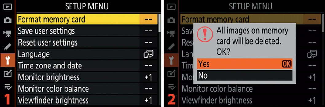
Figure 10.2: Format memory card with Setup Menu screens
Use the following steps to format a memory card:
- 1. Select Format memory card from the Setup Menu and scroll to the right (figure 10.2, image 1).
- 2. The next screen makes it very clear with an ominous-sounding message that you are about to delete all the images on the card you have selected for formatting (figure 10.2, image 2). The screen presents a big red exclamation point and the message All images on memory card will be deleted. OK? If you have decided not to format the card, just select No and press the OK button; otherwise, highlight Yes and press or touch OK to start the format. After you start the formatting operation, you’ll see two popup messages in quick succession. The first will say Formatting memory card. A few seconds later—when the card has been successfully formatted—you’ll briefly see a final message that says Formatting complete. The card is now formatted and you can take lots of pictures.
Settings Recommendation: It is likely best to format each new memory card in the camera before using it for the first time. Some people format their cards in their computers, but that may not be a good idea. Formatting from some computer operating systems may differ from the format used by the camera. Therefore, it is much safer to format the card in-camera only.
Memory Card Information, Error Prevention, and Recovery
Memory card types: The Z6 has one XQD memory card slot, which will soon be compatible with CFexpress memory cards (from a future camera firmware update) if Nikon follows through on its promise to update the camera. XQD and CFexpress cards use the same form factor. While XQD cards are blazingly fast, CFexpress cards are even faster—if the camera’s internal hardware can make use of the extra speed, which is yet to be seen.
Accidental formatting: If you accidentally format a memory card that has unsaved images on it, all is not lost. Formatting doesn’t actually remove any images from the card. Instead, it removes their entries in the memory card’s file allocation table (FAT) so the pictures can no longer be seen or found by the camera. However, you can use card recovery software to rescue most of the pictures if you do not write anything new to the card after you format it. That’s a good thing to remember in case you ever accidentally format a card with images you wanted to keep.
Recovering images from a failed card: In the case of errors and card failures, the manufacturer of your chosen memory card brand usually has a free image recovery utility you can download to your computer. For instance, Sony has recovery software called “Memory Card File Rescue Software” and Lexar provides “Lexar Image Rescue.” Google your card’s brand name followed by “memory card recovery software.” Search YouTube for videos on how to use the software. There are also several aftermarket memory card recovery products available. However, you should do some research before downloading any old image recovery software you find; there are many scammers on the Internet. Stick with companies you know or get a recommendation from your fellow photographers on Nikonians.org!
Individual image deletion: It is not a good idea to delete individual images from your memory card after you have taken them. This can cause future images to become fragmented as the camera tries to make good use of card memory by overwriting old images. If a new larger image cannot fit into the space of a smaller deleted image, the camera will write part of the image to where the smaller image was located, and then write another part of the image elsewhere. If you have a card problem and the images are fragmented, it is much harder to recover the images with image recovery software. It is better to leave all the image files on the card until you transfer them to your computer and then delete the unwanted images there.
Overfilling a memory card: It may not be a good idea to regularly fill up a memory card to the point where the camera can no longer write an image. Memory cards need a little overhead for error provisioning. Most memory cards have some extra space already allocated for error provisioning; however, that space may be gradually used up as the card ages and sectors are marked as bad by the card manager chip. If you have been using a memory card for a while and you regularly fill it up, the card may suddenly fail with no warning because it has run out of room for error provisioning. This is rare, but why take a chance?
Memory card life span: Please remember that memory cards have a certain life span. This is even more important on Z cameras with a single card slot. While a memory card’s lifespan may well be several years, as a card ages it becomes more prone to errors and failure. For important shoots, think carefully about using memory cards that are several years old. While you may get by with it for a while, one day you may have a card failure for the simple reason that the card has no more room for sector errors and subsequently self-destructs. I replace my memory cards at least every two years.
Save User Settings
Save user settings allows you to save up to three user settings. Later you can recall those settings by selecting U1, U2, or U3 from the Mode dial. Each user setting can save most configuration preferences in the Photo Shooting Menu, Movie Shooting Menu, and Custom Setting Menu, along with other specific camera settings. The following lists include items that can and cannot be saved:
Items that can be saved
- Adjustments to one exposure mode (e.g., P, S, A, M) per user setting, including aperture (modes A and M), shutter speed (modes S and M), and flexible program mode (mode P*)
- Exposure and flash compensation (+/− EV settings)
- Flash mode (e.g., Fill flash, Red-eye reduction, Slow sync)
- Focus point (currently active AF point position)
- Metering mode (e.g., Matrix meter, Spot meter)
- Autofocus modes (e.g., Single-servo AF, Continuous-servo AF)
- AF-area modes (e.g., Single-point AF, Dynamic-area AF, Auto-area AF) in both Viewfinder and Live view photography modes
- Bracketing (e.g., Exposure, Flash, White balance, Active D-Lighting)
- Photo Shooting Menu (26 of 33 settings can be saved; seven settings cannot be saved [see next list])
- Movie Shooting Menu (24 of 27 settings can be saved; three settings cannot be saved [see next list])
- Custom Setting Menu (all 51 custom settings a–g)
Items that cannot be saved
- Reset photo shooting, movie shooting, and custom setting menu functions
- Storage folder (100NCZ_6)
- Choose image area settings for still images or video (e.g., FX, DX)
- Manage Picture Control settings for still images or video
- Multiple exposure settings
- Interval timer shooting settings
- Time-lapse photography settings
- Settings on other menus (i.e., Playback Menu, Setup Menu, Retouch Menu, My Menu, or Recent Settings menu)
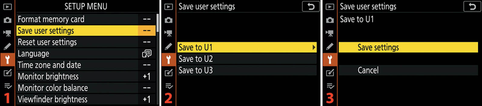
Figure 10.3: Saving a user setting (U1, U2, or U3)
Now let’s examine how to save a user setting. Use the following steps to save one of the three user settings (U1, U2, or U3). This must be repeated for each of the settings:
- 1. Configure your camera’s settings exactly how you want them to be saved for one user setting (U1, U2, or U3). Be sure to configure all the items in the Items that can be saved list that you want to save. When you are finished, set the Mode dial to whatever shooting mode you want to use for the user setting (such as P, S, A, M, Auto). Do not select U1, U2, or U3 on the Mode dial before you save the setting; instead, leave it set to one of the shooting modes.
- 2. Press the MENU button and scroll down to the Setup Menu. Select Save user settings and scroll to the right (figure 10.3, image 1).
- 3. Choose either Save to U1, Save to U2, or Save to U3 from the menu and scroll to the right (figure 10.3, image 2).
- 4. Select Save settings from the menu and press the OK button or tap the option to save the selected setting (figure 10.3, image 3).
Settings Recommendation: Anytime you make a modification to one of the two Shooting Menus or the Custom Setting Menu that you want to reuse, be sure to resave it under one of the user settings. If you are making a temporary change, it isn’t important to save it. The user settings will not change unless you resave them. However, if you want to save a particular configuration for future reuse, just set the camera up the way you want to shoot and save the configuration under one of the user settings. Later, you can retrieve that configuration by simply selecting U1, U2 or U3 on the Mode dial.
Reset User Settings
Reset user settings allows you to reset one of the camera’s user settings back to the factory defaults. The three user settings—U1, U2 and U3—are independent of each other and must be reset individually. If you have a preowned Z6, it is a good idea to reset all three user settings. That way, the user settings are fresh and ready to be configured for your styles of shooting.

Figure 10.4: Resetting a user setting (U1, U2, or U3)
Here’s how to reset one of your camera’s user settings. Repeat these steps for each user setting:
- 1. Select Reset user settings from the Setup Menu and scroll to the right (figure 10.4, image 1).
- 2. Select Reset U1, Reset U2, or Reset U3 and scroll to the right (figure 10.4, image 2).
- 3. Choose Reset or Cancel and press the OK button or tap the option to lock in your setting (figure 10.4, image 3). If you chose Reset, the selected user setting will be reset immediately.
Settings Recommendation: If you bought a used Nikon Z6, why not reset the user settings? That way you can reconfigure the camera to your own styles of shooting. Anytime you want to start over with the Photo Shooting Menu, Movie Shooting Menu, or Custom Settings Menu, be sure to reset the user settings and resave after each reconfiguration.
Language
Language is a function that lets the camera know what language you prefer for the camera’s menus, screens, and messages. The Z6 can display its screens and menus in four languages (firmware C2.00).

Figure 10.5: Language selection
Use the following steps to select your preferred Language:
- 1. Select Language from the Setup Menu and scroll to the right (figure 10.5, image 1).
- 2. Highlight your preferred Language and press the OK button or tap the option to lock in your choice (figure 10.5, image 2).
Settings Recommendation: The camera should come preconfigured for the main language that is spoken where you live. If you prefer a different one, use this setting to select it.
Time Zone and Date
Time zone and date allows you to configure the Time zone, Date and time, Date format, and Daylight saving time settings for your camera.
Let’s examine how to set the various parts of Time zone and date. You may have already done this when you first received your camera. We discussed this briefly in the first chapter.
Time Zone
The Time zone screen for setting the local time zone displays a familiar world map from which you will select the area of the world where you live. Figure 10.6A shows the Time zone configuration screens. The camera displays some major city names and the coordinated universal time (UTC) below the Time zone map (image 3), in case you don’t recognize your location.

Figure 10.6A: Time zone settings
Use the following steps to set the Time zone:
- 1. Follow the screen flow shown in figure 10.6A, images 1 and 2 (Time zone and date > Time zone), until you arrive at the third screen in the series.
- 2. Use the Multi selector pad to scroll left or right, or tap the left and right yellow pointers on the screen, until your location or the nearest city is marked with a small yellow dot (figure 10.6A, image 3). Press or touch OK to lock in the Time zone.
Date and Time
Figure 10.6B shows the Date and time configuration screens. The final screen allows you to select the year, month, and day (Y, M, D), and the hour, minute, and second (H, M, S).
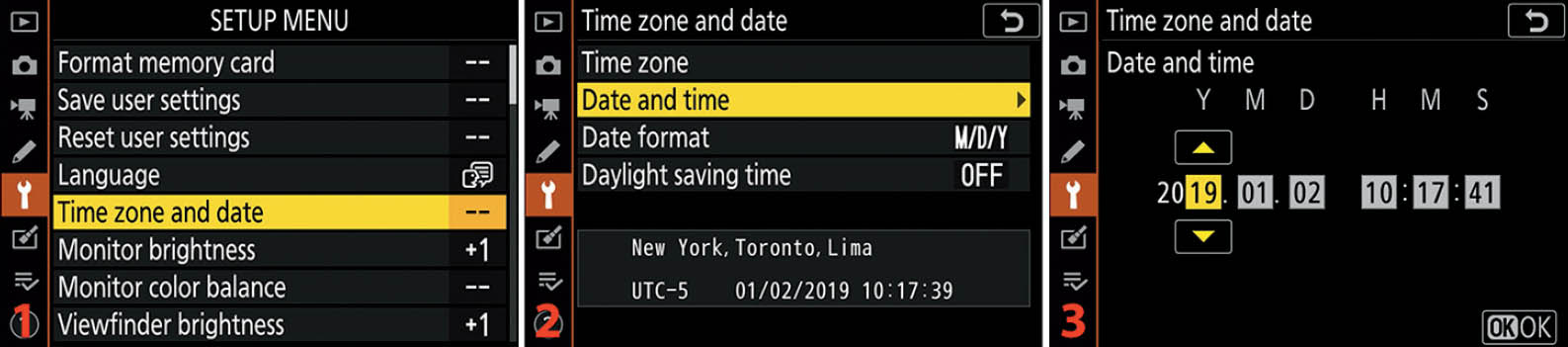
Figure 10.6B: Date and time settings
Use the following steps to set the Date and time:
- 1. Follow the screen flow shown in figure 10.6B, images 1 and 2 (Time zone and date > Date and time), until you arrive at the third screen in the series.
- 2. Use the Multi selector pad to scroll left or right until you’ve selected the value you want to change, or simply tap the option with your fingertip (figure 10.6B, image 3). The Y M D settings on the left are for the year, month, and day. The H M S settings on the right are for the hour, minute, and second. Scroll up or down, or tap the yellow arrows, to change each value. Press or touch OK to lock in the Date and time.
Note: The Z6 uses a 24-hour internal clock instead of the 12-hour clock most of us use. Therefore, to set the clock to 3:00 p.m., for example, you must set the H and M settings to 15:00.
If the clock has been reset due to a dead battery, you’ll see a tiny flashing clock-face indicator on the camera’s displays. It takes about two days of having a charged EN-EL15/a/b battery in the camera to fully charge the built-in clock battery. When the clock battery is fully charged, the clock will remain active without a main camera battery for up to one month.
Date Format
Date format gives you three different ways to format the camera’s date, as follows:
- Y/M/D: Year/Month/Day (2019/12/31)
- M/D/Y: Month/Day/Year (12/31/2019)
- D/M/Y: Day/Month/Year (31/12/2019)

Figure 10.6C: Date format settings
Here are the steps to set the Date format:
- 1. Follow the screen flow shown in figure 10.6C, images 1 and 2 (Time zone and date > Date format), until you arrive at the third screen in the series.
- 2. Choose your favorite Date format from the menu (figure 10.6C, image 3). Press the OK button or tap the option to lock in the setting.
Daylight Saving Time
Some areas of the world observe daylight saving time. On a specified day in spring of each year, many people set their clocks forward by one hour. Then in the fall they set them back, leading to the clever saying “spring forward, fall back.”
If you set Daylight saving time to On, the camera will move the time forward by one hour. In the fall, you will need to remember to change this setting to Off so that the camera will move the time back again. Otherwise, the time stamp on your images will be off by one hour for half the year.

Figure 10.6D: Daylight saving time settings
Here are the steps to enable or disable Daylight saving time:
- 1. Follow the screen flow shown in figure 10.6D, images 1 and 2 (Time zone and date > Daylight saving time), until you arrive at the third screen in the series.
- 2. Figure 10.6D, image 3, shows you the two choices for Daylight saving time: On or Off. If you select On, your camera will move the time forward by one hour from its current setting. Select Off and the camera will move the time back by one hour. This is not an automatic function. You must remember to change this setting each time daylight saving time begins and ends if you are concerned with having a correct time stamp in your picture metadata. If you don’t observe daylight saving time, just leave this set to Off and make sure the camera time matches your local time. Press the OK button or tap your selection to lock it in.
Settings Recommendation: This series includes the first settings you’ll modify when you get a brand-new Z6 camera. It is important that all these items are set correctly because this information is written into the metadata of each image you make. Daylight saving time is optional, but if you use it, you must remember to change it in the fall and spring of each year so your camera’s time will match the local time. I have a reminder set up on my smartphone so that I won’t forget. When you are setting all of your clocks and watches for the semi-annual time change, just remember to set your camera’s internal clock, too.
Monitor Brightness
Monitor brightness is more important than many people realize. If the Monitor is too dim, you’ll have trouble seeing your images in bright light. If it is too bright, you might allow some images to be underexposed because they look fine on the Monitor. Even a seriously underexposed image may look okay on a screen that is too bright. The same goes for video capture.
Additionally, you may need to adjust the Monitor brightness when you are viewing menus or the Information display in bright sunlight or for night shooting. Keeping the Monitor at the right brightness level can be very useful.
The Z6 allows you to adjust the brightness of the Monitor manually. You can select from 10 levels of brightness, varying from −5 to +5.

Figure 10.7: Monitor brightness level adjustment
Use the following steps to adjust the brightness of the camera Monitor:
- 1. Select Monitor brightness from the Setup Menu and scroll to the right (figure 10.7, image 1).
- 2. Use the Multi selector pad or tap the yellow up/down pointers with your fingertip to scroll through the values (−5 to +5). Scroll toward the negative values to dim the Monitor or toward the positive values to brighten it (figure 10.7, image 2). Use the gray-level bars (dark to light) as a guide and adjust the brightness until you can make a distinction between the last two dark bars on the left. That may be the best setting for your camera in the current ambient light. The brightness defaults to 0 (zero), which is right in the middle. Press or touch OK when you’ve found the value you like best.
Note: This function does not affect the exposure of the image. It applies only to the brightness of the Monitor. However, an overly bright or dim Monitor may cause you to adjust the exposure in a detrimental way. Be careful!
Settings Recommendation: I generally leave Monitor brightness set to the +1 setting to allow a tiny bit of extra light for my aging eyes. If you choose to set your camera to a level brighter or dimmer than 0, be sure to check the live histogram (page 68) to validate your exposures. Otherwise, you may find that you are mildly under- or overexposing images because they look fine on the Monitor due to the brightness changes. Learn to use the live histogram for the best pictures!
Monitor Color Balance
Monitor color balance is a function that allows you to control the tint of the camera’s Monitor. If you feel the Monitor has, let’s say, a greenish tint, you can add a little bit of a complementary color to change the color to one that is more acceptable to you.
The effect is not extremely strong, so you will not make your Monitor look garish with this function. However, the color tinting is strong enough that you can overcome any tint you perceive on the Monitor.
This effect does not change the color of your images in any way. It tints the color of the Monitor only, allowing you to balance it against other known color sources.
To balance the Monitor’s color, you should have an image on the Monitor that best reflects your style of photography. That way, once you adjust the colors, you will see what pleases your eye for your main style of picture making.

Figure 10.8: Choosing a sample image for color balancing the Monitor
Use the following steps to choose an appropriate sample picture and color balance your Monitor:
- 1. Choose Monitor color balance from the Setup Menu and scroll to the right (figure 10.8, image 1). The image you last took or viewed on the Monitor will be displayed (figure 10.8, image 2). If this image is acceptable, then you can proceed with color balancing the Monitor.
- 2. To choose a different picture, you can either: display it on the Monitor before selecting Monitor color balance from the Setup Menu, or press the Zoom out button or tap Select img at the bottom of the screen (figure 10.8, image 2), which will open up an image thumbnail view. From this thumbnail screen you can scroll around and select an appropriate picture for your needs (figure 10.8, image 3). Press or touch OK to select the picture you will use to balance the Monitor.
- 3. Now let’s adjust the Monitor color balance. In figure 10.8, image 2, the red arrow is pointing at a small black square in the middle of a color box. The color box and the surrounding G, A, M, and B pointers provide four color axes you can use for color balance adjustment: green (G), amber (A), magenta (M), and blue (B). By moving the small black indicator toward a certain axis, you will add a tint for that color. You can blend the colors to arrive at nearly any tint you prefer by moving the indicator between axes. In figure 10.8, image 4, the yellow arrow is pointing at the small black square, which has been moved equally toward the amber (A) and magenta (M) axes of the color box, warming up the image slightly. To color balance the Monitor to your satisfaction, move the small black square toward certain colors (G, A, M, B) by tapping on the pointers or by scrolling with the Multi selector pad. Once you have arrived at an appropriate color balance, press or touch OK to save the new Monitor color balance. To reset it at any time, simply return the small black square to the middle of the color box.
Settings Recommendation: Since I do not often adjust images in-camera, I will not be influenced by the way the Monitor looks. I mostly use the Monitor to make composition choices and to check the histogram. I think the Monitor on my Z6 is excellent the way it is and have little need for this Monitor color balance function.
However, if I were shooting in a studio, with carefully controlled lighting, and needed to do careful color matching for a product shot, I might be more concerned about Monitor color balance.
Viewfinder Brightness
Similar to Monitor brightness, Viewfinder (EVF) brightness is important. If the EVF is too dim, you may accidentally overexpose your images. If it is too bright, you might allow some images to be underexposed because they look fine in the EVF. Even a seriously underexposed image may look okay on an EVF that is too bright. The same goes for video capture.
The Z6 allows you to adjust the brightness of the EVF manually. You can select from 10 levels of brightness, varying from −5 to +5. Or you can allow the camera to automatically adjust the brightness according to the ambient light level with the Auto mode.

Figure 10.9: Adjusting the brightness of the EVF
Use the following steps to adjust the brightness of the EVF:
- 1. Select Viewfinder brightness from the Setup Menu and scroll to the right (figure 10.9, image 1).
- 2. Choose Auto to let the camera decide how bright the EVF needs to be, or select Manual and scroll to the right to adjust the brightness manually (figure 10.9, image 2).
- 3. If you do not have the camera up to your eye, it is impossible to adjust the Viewfinder brightness manually; therefore, the camera asks you to put your eye up to the Viewfinder to Check the brightness in the viewfinder as you set it (figure 10.9, image 3). Once you place your eye to the Viewfinder you will see the screen shown in figure 10.9, image 4.
- 4. Use the Multi selector pad to scroll through the values (−5 to +5). Scroll toward the negative values to dim the EVF or toward the positive values to brighten it (figure 10.9, image 4). Use the gray-level bars (dark to light) as a guide and adjust the brightness until you can make a distinction between the last two dark bars on the left. That may be the best setting for your camera in the current ambient light. The brightness defaults to 0 (zero), which is right in the middle. Press the OK button when you’ve found the value you like best.
Note: This function does not affect the exposure of the image. It applies only to the brightness of the EVF. However, an overly bright or dim EVF may cause you to adjust the exposure in a detrimental way. Be careful!
Settings Recommendation: I set the Viewfinder brightness to +1 because the EVF seems a little too dark for me at 0. I like the little extra brightness that +1 gives me. You may not need it.
If you choose to set your EVF to a level brighter or dimmer than 0, be sure to check the live histogram (page 68) and validate your exposures. Otherwise, you may find that you are mildly under- or overexposing images because they look fine on the EVF due to the brightness changes. Learn to use the live histogram for the best pictures!
Viewfinder Color Balance
Viewfinder color balance is a function that allows you to control the tint of the camera’s Viewfinder (EVF). If you feel the EVF has, let’s say, a bluish tint, you can add a little bit of a complementary color to change the color to one that is more acceptable to you. The effect is not extremely strong, so you will not make your EVF look garish with this function. However, the color tinting is strong enough that you can overcome any tint you perceive in the EVF.
This effect does not change the color of your images in any way. It only tints the color of the EVF, allowing you to balance it against other known color sources.
To balance the EVF color, you should have an image on the EVF that best reflects your style of photography. That way, once you adjust the colors, you will see what pleases your eye for your main style of picture making.

Figure 10.10: Color balancing the EVF
Use the following steps to color balance the camera’s EVF:
- 1. Display a favorite image on the Monitor and press the MENU button. Choose Viewfinder color balance from the Setup Menu and scroll to the right (figure 10.10, image 1).
- 2. If you do not have the camera up to your eye, it is impossible to adjust the Viewfinder color balance manually; therefore, the camera asks you to put your eye up to the Viewfinder to Check the color balance in the viewfinder as you set it (figure 10.10, image 2). Once you place your eye to the Viewfinder you will see the screen shown in figure 10.9, image 3.
- 3. In figure 10.10, image 3, there is a small black indicator square in the middle of a color box. The color box and the surrounding G, A, M, and B pointers provide four color axes you can use for color balance adjustment: green (G), amber (A), magenta (M), and blue (B). By moving the small black indicator toward a certain axis with the Multi selector pad, you will add a tint for that color. You can blend the colors to arrive at nearly any tint you prefer by moving the indicator between axes. Once you have arrived at an appropriate color balance, press the OK button to save the new Viewfinder color balance. To reset it at any time, simply return the small black square to the middle of the color box.
Settings Recommendation: I mostly use the EVF to make composition choices, to preview the color and contrast of the subject, and to check the histogram for good exposure. I think the color balance of the EVF on my Z6 is excellent the way it is, and I have little need for this Viewfinder color balance function.
However, if I were shooting in a studio with carefully controlled lighting and needed to do careful color matching for a product shot, I might be more concerned about Viewfinder color balance.
Control Panel Brightness
The Control panel on top of the camera gives basic information about settings, including items such as shutter speed, aperture, battery charge, ISO sensitivity, Release mode, and remaining image capacity for the memory card.
The Control panel brightness function lets you control the brightness of this useful little OLED Control panel. Most of us will leave the brightness function set to Auto so that the camera can adjust the Control panel brightness according to ambient light conditions. However, the camera allows you to adjust the brightness manually if you’d like. You can select a brightness level in a range from 1 to 7, or even turn it Off. Let’s see how to adjust the Control panel brightness.

Figure 10.11: Setting the top Control panel brightness
Use the following steps to change the brightness settings for the Control panel on top of the camera:
- 1. Choose Control panel brightness from the Setup Menu and scroll to the right (figure 10.11, image 1).
- 2. If you are like most photographers, the Auto setting is likely the best choice, and it’s the factory default setting (figure 10.11, image 2). Auto lets the camera decide which brightness is best, automatically dimming the Control panel in low light and brightening it in bright light. If Auto is fine with you, highlight it and press the OK button or tap the Auto option to lock it in, and then skip the following steps.
- 3. If you do not use the Control panel and would rather turn it off to save battery, you can do so on the screen shown in image 2 by selecting Off and pressing the OK button or tapping Off with your fingertip. However, if you need to manually control the brightness, you can do so by selecting Manual and scrolling to the right (figure 10.11, image 2).
- 4. The camera offers you an up/down menu with numbers ranging from 1 to 7 (figure 10.11, image 3). Smaller numbers dim the Control panel and higher numbers brighten it. Choose a number by scrolling up or down with the Multi selector pad or tapping on the yellow up/down arrows. Press or touch OK to lock in in the value.
Settings Recommendation: I leave the Control panel brightness set to Auto for my Z6. I don’t use the Control panel on this camera nearly as much as I did with my Nikon DSLRs, but it still comes in handy for a quick look at or selection of important settings.
If you are doing night photography, would like to save battery power, or just don’t need the Control panel, you can turn it off. If you need to make it very dim or very bright, then you can control the brightness manually.
Limit Monitor Mode Selection
Limit monitor mode selection allows you to choose which modes are available when you press the Monitor mode button on the side of the camera’s Viewfinder (figure 10.12A, image 3, red arrow).
Here is a description of the four available modes, followed by how to enable or disable individual modes:
- Automatic display switch: When this mode is selected the camera will use its Eye sensor to detect when your eye is at the Viewfinder and switch the display output to the EVF. If nothing is near the Eye sensor, the camera uses the rear Monitor instead. (See the upcoming subsection, Cautionary Note on Using the Eye Sensor.)
- Viewfinder only: The camera uses the EVF only and leaves the Monitor turned off. Nothing will be displayed on the Monitor, even if you try to use a function that normally appears on the Monitor. The EVF is the camera’s main display in this mode.
- Monitor only: The camera uses the Monitor only and leaves the EVF turned off. Nothing will be displayed on the EVF, even if you put your eye up to the Viewfinder. The Monitor is the camera’s main display in this mode.
- Prioritize viewfinder: This mode makes the camera act more like a DSLR. The Monitor stays off until it needs to display a just-captured image or video—and your eye is not peering into the EVF. In effect, the EVF is prioritized, with the camera using the Monitor only when required by you, such as for image or video playback (i.e., you press the Playback button or the MENU button with your eye away from the Viewfinder).

Figure 10.12A: Choosing which Monitor/EVF modes are available
Use the following steps to limit which Monitor modes your camera will offer you when you press the Monitor mode button:
- 1. Choose Limit monitor mode selection from the Setup Menu and scroll to the right (figure 10.12A, image 1).
- 2. To enable or disable one or more of the Monitor modes, you must check or uncheck each mode individually (figure 10.12A, image 2). Highlight one of the Monitor modes and scroll to the right to check or uncheck that mode. You can also tap a check box to add or remove a check mark. When you’ve checked only the modes you want to use, press or touch OK to lock in your choices.
- 3. Only modes that have check marks to the left of the name will be available when you press the Monitor mode button (figure 10.12A, image 3, red arrow). The camera will present a different mode on the Monitor or in the EVF with each press of the button—such as you see in figure 10.12A, image 4 (e.g., Automatic display switch). To select a Monitor mode, press the Monitor mode button (image 3) until the mode you desire to use shows on the Monitor or in the EVF.
Settings Recommendation: I normally leave the mode set to Automatic display switch for convenience. When I am out doing a walkabout, I may use Prioritize viewfinder, which makes the Monitor stay off except for displaying an image after I take it. I rarely use the Monitor only or Viewfinder only settings. However, I leave them available in case I need them.
Cautionary Note on Using the Eye Sensor
The Eye sensor is very sensitive. I was taking pictures on a rainy day in the mountains and a pinhead-sized rain droplet got on the sensor. The camera then refused to use the rear Monitor. I thought my new camera was ruined from being too wet, but then I noticed the tiny droplet, removed it, and all was well.

Figure 10.12B: Results from shooting all day in the rain in Great Smoky Mountains, Tennessee, USA.
I shot for several hours in a light rain, occasionally wiping the camera off with a lens cleaning cloth. The camera performed flawlessly (see figure 10.12B). Just keep dust and water droplets off the little dark rectangle at the top of the Viewfinder opening—that’s the Eye sensor location.
Information Display
The Information display setting allows your camera to automatically sense how much ambient light there is in the area where you are shooting and adjust the color and brightness of the Information display screen accordingly. If the ambient light is bright, the color of the physical Information display screen will also be bright so that it can overcome the ambient light.
To open the Information display screen, press the DISP button multiple times until the Information display appears (figure 10.13A). Once you see the Information display, pressing the i button will bring up the i menu at the bottom of the screen, with the Information display at the top. The Information display screen shows the current shooting information: shutter speed, aperture, ISO, and frame count, plus the 12 items that are adjustable on the i menu.

Figure 10.13A: Dark on light and Light on dark display screens
In the Light on dark screen shown in figure 10.13A, I brightened the screen’s gray text considerably so that it is clear in the printed book. In real life it is dimmer than shown here to allow you to keep your night vision.

Figure 10.13B: Setting Information display to Auto
Use the following steps to configure the Information display:
- 1. Select Information display from the Setup Menu and scroll to the right (figure 10.13B, image 1).
- 2. Choose B Dark on light or W Light on dark and press the OK button or tap the option to lock in your setting (figure 10.13B, image 2).
Settings Recommendation: I leave Information display set to Dark on light for normal use. However, when I am doing night photography, the much dimmer Light on dark setting protects my night vision.
AF Fine-Tune
The AF fine-tune function allows you to manually adjust your camera to a particular lens so the lens focuses where you want it to focus.
Nikon has made provisions for keeping a table of up to 30 lenses fine-tuned for better focus. The idea behind fine-tuning is that you can push the focus forward or backward in small increments, with up to 20 increments in each direction (−20 to +20).
Once you have fine-tuned the autofocus system for a particular lens, the actual focus is moved from its default position forward or backward by the amount you’ve specified in the fine-tuning operation. If your lens has a consistent back focus problem and you move the focus a little forward, the problem is solved.
First let’s see how to access the fine-tuning system, and then we will examine each of its four subsettings in detail (figure 10.14A, image 2).

Figure 10.14A: Fine-tuning the focus of a lens
Use the following steps to start the process of fine-tuning a lens (figure 10.14A):
- 1. Choose Setup Menu > AF fine-tune (figure 10.14A, image 1).
- 2. The next four subsections show the screens used to configure AF fine-tune (figures 10.14B to 10.14E). Each of the following figures continues where figure 10.14A, image 2, ends.
AF Fine-Tune (On/Off)

Figure 10.14B: Enabling or disabling AF fine-tune
Figure 10.14B shows the AF fine-tune (On/Off) screen and its selections. The two values you can select are as follows:
- On: This setting enables the AF fine-tune system. Set AF fine-tune (On/Off) to On if you are planning to fine-tune a lens now. Press the OK button or tap the option to save the value.
- Off: When AF fine-tune (On/Off) is set to Off, the camera focuses like a factory default Z6, with no fine-tuning applied. This default setting disables the AF fine-tune system.
Saved Value

Figure 10.14C: Fine-tuning a lens with a Saved value
With an autofocus lens mounted, Saved value allows you to control the amount of front or back focus fine-tuning you would like to input for the listed lens. At the top left of figure 10.14C, image 2, just under the words Saved value, you’ll see the focal length of the lens that is mounted on the camera, the aperture range (F4), and the number assigned to the lens. If you’re configuring a lens for the first time, you’ll see NO. – –. You can fine-tune a maximum of 30 lenses. After you save a lens configuration, a lens number will appear in place of the dashes (NO. 0 to NO. 99). We’ll discuss how to assign a lens a certain number between 0 and 99 shortly.
To the right of the lens information is a scale that runs from +20 on the top to −20 on the bottom. The yellow pointer on the right starts out at 0. You can move this yellow pointer up or down to change the amount of focus fine-tuning you need for this lens. Moving the pointer up on the scale pushes the focal point away from the camera, and moving it down pulls the focal point toward the camera. I set my Nikkor Z 24–70mm F/4 S lens to +5 forward focus, as shown in figure 10.14C, image 2. When you set the fine-tuning amount you need, press or touch OK to save it.
Default
The Default configuration screen looks a lot like the Saved value screen, except no lens information is listed. This Default value will be applied to all AF lenses you mount on your camera. If you are convinced that your particular camera (not a lens) always has a back or front focus problem and you are not able or ready to ship it off to Nikon for repair, you can use the Default value to push the autofocus in one direction or the other until you are satisfied that your camera is focusing the way you’d like. Again, this will affect all autofocus lenses you mount on your camera.
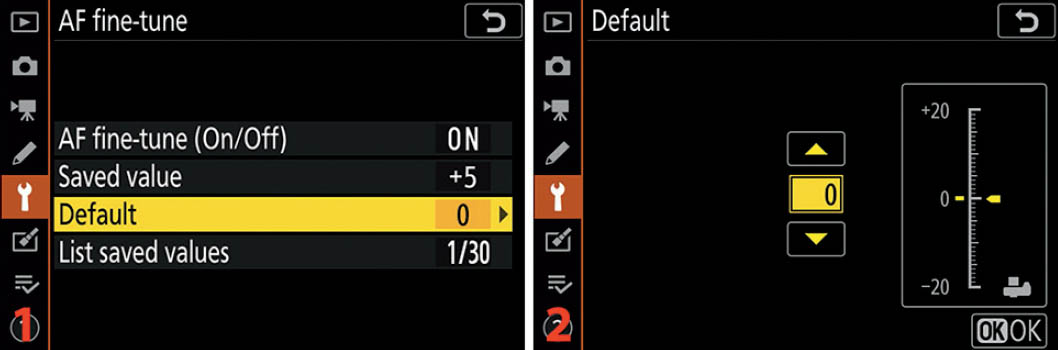
Figure 10.14D: Setting a Default fine-tune adjustment for all lenses
As shown in figure 10.14D, image 2, to set an AF fine-tune > Default value, use the scale that runs from +20 on the top to −20 on the bottom. The yellow pointer starts at 0. You can move this yellow pointer up or down to change the amount of focus fine-tuning you need for every autofocus lens you will mount on the Z6, if no value already exists in the Saved value for a particular lens (Saved value overrides Default).
Moving the pointer up on the scale pushes the focal point away from the camera (front focus), and moving it down pulls the focal point toward the camera (back focus). When you are done, press or touch OK. Be careful with this setting. Most people will not use it because it applies an AF fine-tune value to any AF lens mounted on the camera, whether that lens needs fine-tuning or not.
Note: You could use this Default value as a value for any of your AF lenses that do not have a Saved value. I tested this with a different lens (not shown) by setting a Saved value of +1 for my AF-S Nikkor 24–120mm lens. While the 24–120mm lens was still mounted, I set a value of −2 for the Default value. When I removed the 24–120mm lens and mounted an AF Nikkor 60mm micro lens, the +1 in the Saved value field disappeared, but the −2 in the Default field stayed put. So it appears that you can use the Default field either for all AF lenses that have no Saved value or for a currently mounted AF lens that you want to adjust but not save a value for.
List Saved Values
Notice in figure 10.14E that there are several screens used to configure the list of saved values. List saved values helps you remember which lenses you’ve fine-tuned. It allows you to set an identification number (00–99) for a particular lens out of the 20 lenses you can register.
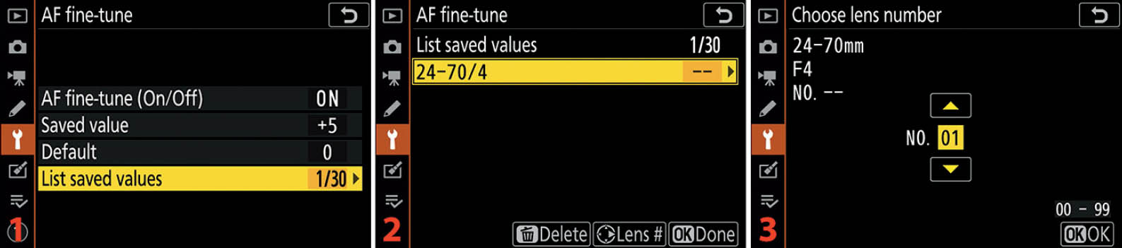
Figure 10.14E: Assigning an AF fine-tune lens number to one of your 20 lenses
In figure 10.14E, image 2, you can see my 24–70mm F/4 lens listed (24–70/4). This List saved values screen will show a list of all the lenses for which you have saved values—my camera just happens to have saved values for only one lens.
Some photographers use the last two digits of a lens’s serial number as the Saved value identification number for that lens. Use the screen shown in figure 10.14E, image 3, to select any number from 00 to 99. Scroll up or down with the Multi selector pad or tap the up/down pointers on the screen to change the number in the yellow box.

Figure 10.14F: NO. 1 set under Save value
You will see the results of this change when you examine the Saved value screen, as shown in figure 10.14F, image 2. Instead of NO. – –, the screen in image 2 now reports NO. 1 (compare to figure 10.14C, image 2).
You can have up to 30 lenses listed on the List saved values screen (figure 10.14E, image 2), with each lens having a different number from 00 to 99.
Settings Recommendation: AF fine-tune is good to have. If I buy a new lens and it has focus problems, I don’t keep it. Back it goes to the manufacturer for a replacement. However, if I buy a used lens or have had one long enough to go out of warranty and it later develops front or back focus problems, the camera allows me to fine-tune the autofocus for that lens.
Non-CPU Lens Data
Non-CPU lens data helps you use older non-CPU Nikkor lenses with your camera. Do you still have several older AI or AI-S Nikkor lenses? I do! The image quality from the older manual focus (MF) lenses is excellent.
Since the Z6 is positioned as an advanced enthusiast and pro camera, it must have the necessary controls to use both auto focus (AF) and manual focus (MF) lenses. Many photographers on a budget use the older MF lenses on a Nikon FTZ adapter to obtain professional-level image quality without having to break the bank on expensive lens purchases. You can buy excellent AI and AI-S Nikkor MF lenses on eBay for $100–$400, and with them you can achieve image quality that only the most expensive autofocus lenses can produce. Additionally, with all the aftermarket lens adapters currently available for the Z-camera line, MF lenses of all sorts and brands are available for photographers who like to experiment with non-Nikon lenses.
It’s important to have a way to let the Z6 know something about the lens in use. This Non-CPU lens data function allows you to do exactly that. You can store information for up to 20 separate non-CPU lenses within this section of the Z6.
Here is an analysis of the Non-CPU lens data screen selections (figure 10.15A, image 2):
- Lens number: Using the Multi selector pad, you can scroll left or right to select one of your lenses. There are 20 lens records available. When you select a Lens number here, the focal length and maximum aperture of that lens will show up in the Focal length and Maximum aperture fields. If you haven’t stored information for a particular Lens number, you’ll see double dashes (– –) in the Focal length and Maximum aperture fields.
- Focal length (mm): This field contains the actual focal length in millimeters (mm) of the lens in use. You can select focal lengths from 6mm to 4000mm. Hmm, I didn’t know they even made a 4000mm lens. I want one!
- Maximum aperture: This field is for the Maximum aperture of the lens. You can enter an f-stop number from F1.2 to F22. Remember, this is for the maximum aperture only (largest opening or f-stop).

Figure 10.15A: Non-CPU lens data
Use the following steps to configure (save) each of your non-CPU lenses for use with your Z6:
- 1. Select Non-CPU lens data from the Setup Menu and scroll to the right (figure 10.15A, image 1).
- 2. Choose Lens number and scroll left or right until you find the number you want to use for this particular lens (figure 10.15A, image 2).
- 3. Scroll down to Focal length (mm) and scroll left or right to select the focal length of the lens (figure 10.15A, image 3). If you are configuring a non-CPU zoom lens, select the widest setting. This works because the meter will adjust for any light falloff that may occur as the lens is zoomed out.
- 4. Scroll down to Maximum aperture and scroll left or right to select the maximum aperture of the lens (figure 10.15A, image 4). If you are configuring a variable-aperture zoom lens, select the largest aperture the lens can use (e.g., f/2.8). This works because the meter will adjust for the variation in the aperture.
- 5. Press or touch OK to store the setting.
The screen shown in figure 10.15A, image 2, allows you to either select a lens or save changes to one or all 20 of your lenses. In other words, you can use the set of screens in figure 10.15A to both input and select a non-CPU lens.
When you have selected a lens for use, the Setup Menu > Non-CPU lens data selection will show the number of the lens you’ve selected. It will be in the format of No. 1 to No. 20. In figure 10.15A, image 1, you can see the lens selection (No. 1) at the end of the Non-CPU lens data line. That’s my beloved AI Nikkor 35mm f/2 lens!
Selecting a Non-CPU Lens with External Camera Controls
As we discussed in the previous chapter, the Z6 allows you to customize several of its buttons and controls with various options, one of which allows you to select a non-CPU lens.
If you frequently use several manual-focus non-CPU lenses, you can use the Custom Setting Menu to assign the setting called Choose non-CPU lens number to one of the camera’s buttons (Custom Setting Menu > f Controls > f2 Custom control assignment; page 423). This will allow you to select Non-CPU lens data very quickly. You hold down the assigned button (e.g., Fn1, Fn2) and turn either of the Command dials to select one of the 20 non-CPU lenses you have registered with the camera.
To select a non-CPU lens using external camera controls (after making an assignment to one of the camera’s buttons), hold down the button you’ve assigned (e.g., Movie record button) and turn either Command dial until the number of your lens is highlighted in yellow (No. 1 to No. 20; figure 10.15B), then release the button. Now your camera knows which lens is mounted. The focal length and maximum aperture (e.g., 200mm F4) of the selected non-CPU lens will appear at the top of the screen.

Figure 10.15B: Non-CPU lens data from assigned button
Using the FTZ Adapter with Non-CPU Lenses
Because the FTZ adapter does not have an aperture indexing prong and cannot manually connect to a lens, the Z6 has no way to know which aperture the camera is using with non-CPU lenses. If you examine the internal metadata of an image you have taken with a non-CPU lens, using the camera’s Overview screen (page 148), you will notice that the camera registers only the maximum aperture of the non-CPU lens—the one you previously entered—and not the actual aperture you used to take the picture. This is because the camera has no idea which aperture you have selected. In fact, you will notice that the top Control panel, EVF, and Monitor will be flashing “F– –“ the entire time you have a non-CPU lens mounted. The Z7/Z6 User’s Manual lists this as an error (page 164); however, in this case it simply means the camera cannot determine which aperture is in use. Ignore the flashing “F– –“ and use stop-down metering with assistance from the live histogram (page 68) to obtain an accurate exposure. If you have favorite non-CPU lenses that you want to use frequently, you can find a company that will add a CPU chip to a non-CPU lens so that it will pass aperture information. Using focus Peaking (page 409) with non-CPU lenses will help you achieve excellent manual focus.
Clean Image Sensor
Clean image sensor is Nikon’s helpful answer to dust spots on your images that are due to a dirty imaging sensor. Dust is everywhere and will eventually get on your camera’s sensor. The Z6 cleans the sensor by vibrating the entire sensor unit. These high-frequency vibrations will hopefully dislodge dust and make it fall off the filter so you won’t see it as spots on your pictures.
The vibration cleaning method seems to work pretty well. Of course, if sticky pollen or other moist dust gets into the camera, the vibration system won’t be able to remove it. Then it may be time for brush or wet cleaning.
Clean Now
Clean now allows you to clean the imaging sensor at any time. If you detect a dust spot, or just get nervous because you are in a dusty environment with your Z6, you can simply select Clean now and the camera will execute a sensor cleaning cycle.

Figure 10.16A: Clean now screens
Use the following steps to clean the camera’s sensor immediately:
- 1. Select Clean image sensor from the Setup Menu and scroll to the right (figure 10.16A, image 1).
- 2. Select Clean now from the menu and press the OK button or tap the option with your fingertip (figure 10.16A, image 2).
- 3. Step 2 starts the automatic cleaning process. A screen will appear that says Cleaning image sensor (figure 10.16A, image 3). When sensor cleaning is finished, a screen that says Done will briefly appear (not shown in figure). Then the camera switches back to the Setup Menu.
Now, let’s examine how to select an active method for regular sensor cleaning.
Automatic Cleaning
For preventive dust control, some photographers set their cameras to clean the sensor at shutdown. There are two selections for Automatic cleaning:
- Clean at shutdown
- Cleaning off
These settings are self-explanatory. I find it interesting that I don’t detect any shutdown delay when using Clean at shutdown mode. I can turn my camera on and immediately take a picture. The cleaning cycle seems to be very brief, or at least interruptible, in this mode.

Figure 10.16B: Automatic cleaning screens
Use the following steps to enable or disable Automatic cleaning:
- 1. Select Clean image sensor from the Setup Menu and scroll to the right (figure 10.16B, image 1).
- 2. Choose Automatic cleaning from the menu and scroll to the right (figure 10.16B, image 2).
- 3. Select Clean at shutdown to enable Automatic cleaning, or select Off to disable it (figure 10.16B, image 3). Clean at shutdown seems to be the best choice for most photographers. Press the OK button or tap the option to lock in your choice.
Nikon suggests that you hold the camera at the same angle as when you are taking pictures (bottom down) when you use these modes to clean the sensor.
Settings Recommendation: I leave my camera set to Clean at shutdown. That way it will do a cleaning cycle every time I turn the camera off. It doesn’t seem to slow down shooting; I can still turn on the camera and immediately begin taking photographs. A little sensor cleaning in this dusty world seems like a good idea to me.
Image Dust Off Ref Photo
You may go out and do an expensive shoot only to return and find that some dust spots have appeared in the worst possible places in your images. If you immediately create an Image Dust Off ref photo, you can use it to remove the dust spots from a series of images, and then you can clean the camera’s sensor for your next shooting session.
When you use the following instructions to create the Image Dust Off ref photo, you’ll be shooting a blank, unfocused picture of a pure white or gray background. The dust spots in the image will then be readily apparent to Nikon Capture NX-D software. Yes, you must use Nikon’s free software to automatically batch-remove dust spots from a large number of images.
When you load the image(s) to be cleaned into Capture NX-D, along with the Image Dust Off ref photo, the software will use the Image Dust Off ref photo to automatically remove the dust spots in your pictures.
The position and amount of dust on the sensor may change. You should take Image Dust Off ref photos regularly and use one that was taken within one day of the photographs you wish to clean up.
Finding a Subject for the Dust-Off Reference Photo
First, you’ll need to select a featureless subject to make a photograph for the Image Dust Off ref photo. The key is to use a material that has no graininess, such as a bright, well-lit white card. I tried using plain white sheets of paper held up to a bright window, but the resulting reference photo was unsatisfactory to Capture NX-D. It gave me a message that my reference photo was too dusty when I tried to use it.
After some experimentation, I finally settled on three different subjects that seem to work well:
- A slide-viewing light table with the light turned on
- A computer monitor with a blank white word processor document
- A plain white card under bright light
All of these were bright and featureless enough to satisfy both my camera and Capture NX-D. The key is to photograph something fairly bright, but not too bright. You may need to experiment with different subjects if you don’t have a light table or computer.
Now, let’s prepare the camera for the actual reference photo.

Figure 10.17A: Image Dust Off ref photo settings
Here are the steps you’ll use to create an Image Dust Off ref photo:
- 1. Select Image Dust Off ref photo from the Setup Menu and scroll to the right (figure 10.17A, image 1).
- 2. Choose Start and press the OK button, or tap Start with your fingertip (figure 10.17A, image 2). (There is also a Clean sensor and then start selection. However, since I want to remove dust on current pictures, I won’t use this setting. It might remove the dust bunny that is imprinted on the last 500 images I just shot! I’ll clean my sensor after I get a good Image Dust Off ref photo. Choose Clean sensor and then start only if the Image Dust Off ref photo will not be used with existing images!)
- 3. Once you’ve selected Start, you’ll see the characters rEF on the screen (figure 10.17A, image 3, red arrow). This simply means that the camera is ready to create the image. When the camera displays the screen in figure 10.17A, image 3, hold the lens about 4 inches (10 cm) away from a blank subject. The camera will not try to autofocus during the process, which is good because you want the lens at infinity. You are not trying to take a viewable picture; you’re creating an image that shows where the dust is on the sensor. Focus is not important, and neither is minor camera shake.
- 4. If you try to take the picture and the subject is not bright enough, too bright, or too grainy (not featureless), you will see the screen shown in figure 10.17B. If you are having problems with too much brightness, use a gray surface instead of white. Most of the time this error is caused by insufficient light. If you don’t see the screen in figure 10.17B and the shutter fires, you have successfully created an Image Dust Off ref photo. You can double-check that you were successful by pressing the Playback button.
- 5. If you see the image shown in figure 10.17C on your camera screen, the reference photo was captured. A file of approximately 16 MB is created on your camera’s memory card with a filename extension of .NDF (an example file name is DSC_1234.NDF). This NDF file is basically a small database of the millions of clean pixels in your imaging sensor and a few dirty ones. You cannot display the Image Dust Off ref photo on your computer. It will not open in Nikon Capture NX-D or any other graphics program that I tried. It is used only as a reference by Capture NX-D when it’s time to clean images.

Figure 10.17B: Image Dust Off ref photo failure
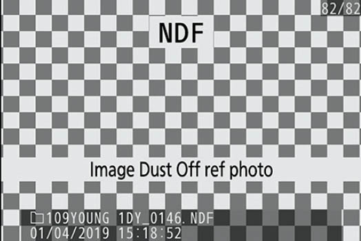
Figure 10.17C: Successful Image Dust Off ref photo
Using Capture NX-D to Remove Dust Spots
To store the reference photo for later use in removing spots, copy the NDF file (figure 10.17C) from your camera’s memory card to the computer folder containing the images that have dust spots on them, the ones for which you created this Image Dust Off ref photo. You can use the Image Dust Off function (figure 10.17D) in Nikon Capture NX-D to remove the dust spots from all of the images represented by the Image Dust Off ref photo.
In figure 10.17D, the red-rimmed cutout in the middle is an enlargement of the Window > Edit > Camera and Lens Corrections window in the control bar on the right side of Capture NX-D version 1.5.0.
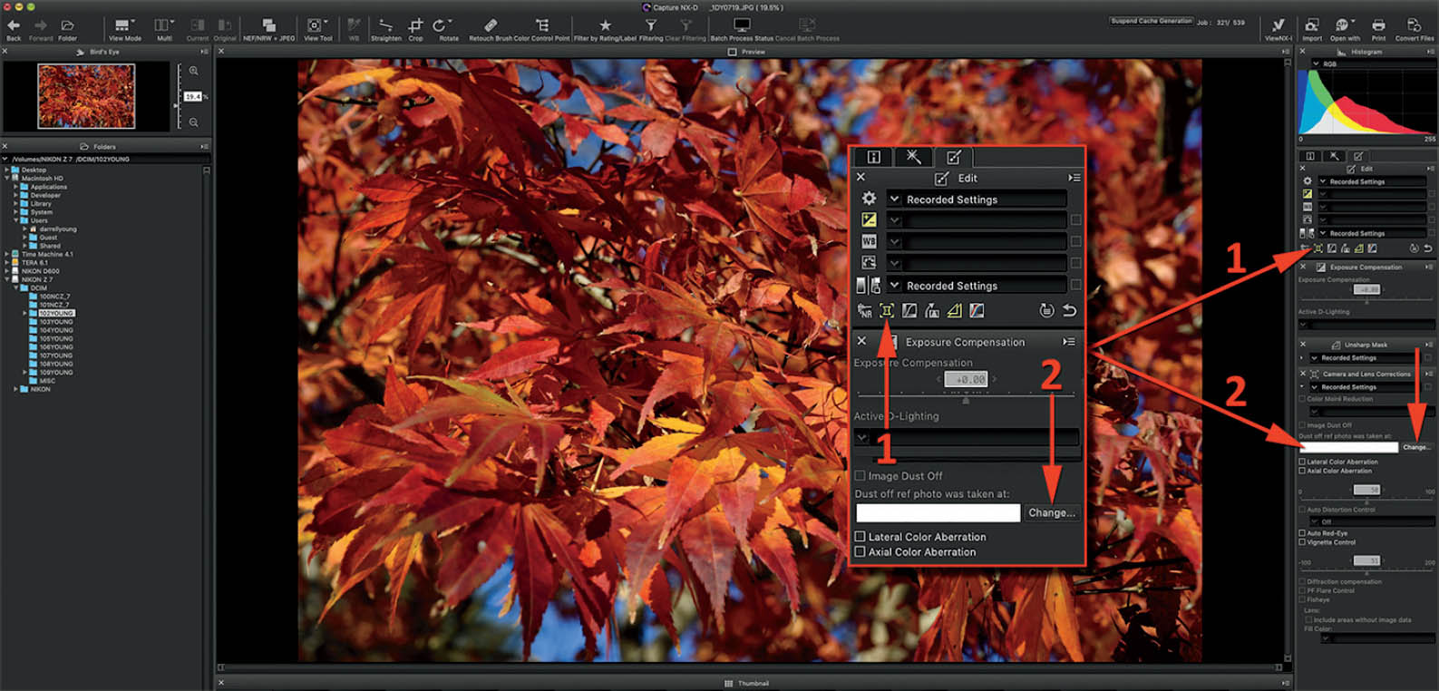
Figure 10.17D: Nikon Capture NX-D’s Image Dust Off function
Here are the steps to use the Image Dust Off functions in Nikon Capture NX-D to remove dust from a group of images, using an Image Dust Off ref photo (figure 10.17D):
- 1. Copy your images into a folder on your computer, along with the Image Dust Off ref photo. It is best if they are in the same folder to make sure they represent the images you recently shot. You can browse to a different folder if you want to store the dust off photo elsewhere.
- 2. Now, open Capture NX-D and use the folder browser on the left side of the screen to browse to the folder that contains your images and the dust off photo.
- 3. Click on the Edit tab on the right side of the screen, and then click on the Camera and Lens Corrections icon (figure 10.17D, arrow 1).
- 4. Select the image you want to process and make sure it is shown large in the center section of Nikon Capture NX-D. Wait a moment—when the software detects a dust off ref photo in the folder, the Change button (figure 10.17D, arrow 2) will become available.
- 5. Click on the Change button and a query window will open with the following question: Do you want to use a Dust off ref photo that is in the same folder as the active image? Click the Yes button and Capture NX-D will process the images in the folder against the Image Dust Off ref photo, removing the dust spots from all the images in the folder. It will take some time to process the image, and the computer will show a wait indicator until the picture is processed. Capture NX-D does not inform you that it is done, but when the hourglass or other wait indicator goes away the process is complete.
- 6. In the text field next to the Change button, check to see the date-and-time stamp of the Image Dust Off ref photo used to correct the image. It will look like this: “2019/04/30 15:50:10.”
Settings Recommendation: Nikon Capture NX-D is free, and it’s a good form of insurance, even if you use it for nothing more than removing dust from your images. Whenever you find yourself out in nature or shooting in an environment that might be dusty, why not create an Image Dust Off ref photo as the last photo of the day? That dust off photo may save you a lot of dust removal work. Let Capture NX-D do it for you!
Additionally, Nikon has recently added the “color control points” back into the Capture software. Many of us used those powerful control points in Nikon Capture NX-2 to selectively post-process exact areas of the image. When Nikon stopped supporting Capture NX-2 and brought out NX-D instead, the color control points were missing. Well, with version 1.5.0 of Capture NX-D, the powerful color control points are back! Download the free Nikon Capture NX-D at the following website:
http://downloadcenter.nikonimglib.com/en/products/162/Capture_NX-D.html
If for some reason the URL doesn’t work, just Google “Download Nikon Capture NX-D” and I’m sure you will find it.
White Card Tip
Remember, all your camera needs to create an Image Dust Off ref photo is a good look at its imaging sensor so it can map the dust spots into an NDF file (ref photo file). If you get the warning screen shown in figure 10.17B that says exposure settings are not appropriate, change the exposure settings and try again with a nice bright, clean, white surface. Put the lens very close to the surface, and make sure it is not in focus. Nikon recommends less than 4 inches (10 cm). You might even want to manually set the lens to infinity if you are having problems with this. When you’ve found your favorite white or gray surface for Image Dust Off ref photos, keep it safe and use it consistently.
Image Comment
Image comment is a useful setting that allows you to attach a 36-character comment to each image you shoot. The comment is embedded in the picture’s internal metadata and does not show up on the image itself. I attach the comment “Photo by Darrell Young” to my images.
You could include your copyright here, even though the camera has a place to put Copyright information (see the next section), or you could insert a comment with some details about the picture series.
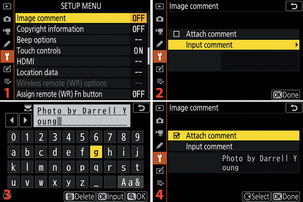
Figure 10.18: Attaching an Image comment
Use the following steps to create an Image comment:
- 1. Select Image comment from the Setup Menu and scroll to the right (figure 10.18, image 1).
- 2. Select Input comment from the menu and scroll to the right (figure 10.18, image 2).
- 3. The comment entry keyboard is shown in figure 10.18, image 3. You can insert an image comment by tapping the characters you want to use on the Monitor, and they will appear in the position marked with the dark-gray cursor in the comment field (Photo by Darrell Young). You can enter up to 36 characters. Use the left/right arrow tip touch controls in the top-left corner to move left and right in the comment field. To change from upper to lower case—or to access symbols, such as #—tap the Aa& control in the lower-right corner of the screen (just above the OK touch control). If you make a mistake, position the dark gray cursor over the error and tap the Delete control at the bottom of the screen. When you’ve finished entering the comment, press or touch OK to save it. You will see the word Saved appear briefly on the Monitor. (Note: If you would prefer not to use the touch-screen features, you can move the selection cursor with the Multi selector pad to highlight a character in the list below the comment field, then press the OK button to insert the character. To correct an error, turn the rear Main command dial to move back and forth along the field that contains the new comment, and press the Delete button to remove the error. Press the OK button when you are finished entering the comment.)
- 4. The camera will switch back to the Image comment screen (figure 10.18, image 4). Now you must put a check mark in the Attach comment check box so the comment will attach itself to each new image you take. To toggle a check mark on or off in the check box, highlight the Attach comment line and scroll to the right with the Multi selector pad, or tap the check box with your fingertip.
- 5. Press or touch OK (Done) to save the new comment.
Settings Recommendation: You can use this comment field for any text you want to add to the internal metadata of the image (up to 36 characters). There is another Setup Menu selection called Copyright information (see the next section) that allows you to add your personal copyright. I added basic “who took it” information here because I am worried about image theft. You may want to add other text—since the camera provides a specific Copyright information screen—such as information to identify the shoot. Remember, you are limited to 36 characters in the comment.
Copyright Information
Copyright information allows you to embed Artist and Copyright data into each image. Refer to figure 10.19 and use the following steps to add personal information to your camera. Your Artist name and Copyright information will then be written into the metadata of each of your images, but is not visible on the image itself.

Figure 10.19: Copyright information settings
Here are the steps to enter your Artist and Copyright information:
- 1. Select Copyright information from the Setup Menu and scroll to the right (figure 10.19, image 1).
- 2. Scroll down to Artist and scroll to the right (figure 10.19, image 2).
- 3. The data entry keyboard is shown in figure 10.19, image 3. You can insert your name (or other information) by tapping the characters you want to use on the Monitor, and they will appear in the position marked with the dark-gray cursor in the data entry field (Darrell Young). You can enter up to 36 characters. Use the left/right arrow tip touch controls in the top-left corner to move left and right in the field. To change from upper to lower case—or to access symbols, such as #—tap the Aa& control in the lower-right corner of the screen (just above the OK touch control). If you make a mistake, position the dark-gray cursor over the error and tap the Delete control at the bottom of the screen. When you have entered your information, press or touch OK to save it. (Note: If you would prefer not to use the touch-screen features, you can move the selection cursor with the Multi selector pad to highlight a character in the list below the data entry field, then press the OK button to insert the character. To correct an error, turn the rear Main command dial to move back and forth along the field that contains the new comment, and press the Delete button to remove the error. Press the OK button when you have finished entering your information.) Now scroll down to the Copyright line on the Copyright information screen and scroll to the right (figure 10.19, image 4).
- 4. Add your name using the method and controls described in step 3, and then press or touch OK to save the Copyright (figure 10.19, image 5).
- 5. Scroll up to the Attach copyright information line (figure 10.19, image 6). You must put a check mark in the Attach copyright information check box so the Artist and Copyright information will attach itself to each new image you take. Scroll to the right with the Multi selector pad, or tap the check box, and you’ll see a tiny check mark appear in the box.
- 6. Press or touch OK to save your Artist and Copyright information.
Settings Recommendation: Be sure to add your name in both the Artist and Copyright sections of this function. With so much intellectual property theft going on these days, it’s a good idea to identify each of your images as your own. Otherwise, you may post an image on Instagram or Facebook to share with friends and later find it on a billboard along the highway. With the Artist and Copyright information embedded in the image metadata, you will be able to prove that the image is yours and charge the infringer.
Embedding your personal information is not a foolproof way to identify your images because unscrupulous people may steal them and strip the metadata out of them. However, if you do find one of your images on the front page of a magazine or on someone’s website, you can at least prove that you took the image and have some legal recourse under the Digital Millennium Copyright Act (DMCA). When you’ve taken a picture, you own the copyright to that image. You must be able to prove you took it. This is one convenient way.
You’ll have even more power to protect yourself if you register your images with the U.S. Copyright Registry at the following web address:
https://copyright.gov/registration/
If you sell your camera, or loan it to someone, be sure to remove the Artist and Copyright information to prevent misuse of your name. You can either remove it manually or use Setup Menu > Reset all settings, which resets all camera settings back to their factory defaults.
Beep Options
The Beep options setting allows your camera to make a beeping sound (if enabled) to alert you during the following events:
- Focus lock while in Single-servo AF (AF-S) mode, if Focus is selected for Custom setting a2 (page 366)
- Countdown in Self-timer mode operations
- At the end of Time-lapse movie
- When the touch screen is used for keyboard entry
You can set the camera to beep with a high- or low-pitched tone, and you can adjust the volume of the beep—or you can turn the beep sound off. When Beep is active, you’ll see a little musical note displayed in the Information display on the Monitor, and of course, you will hear the camera beeping when you do the things in the list.
First let’s examine how to turn the Beep sound on or off. It defaults to Off in the Z6.
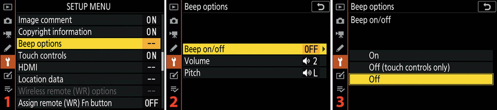
Figure 10.20A: Enabling or disabling the camera’s Beep sound
Use the following steps to enable or disable the camera’s beep sound:
- 1. Follow the screen flow in figure 10.20A, images 1 and 2 (Beep Options > Beep on/off), until you arrive at the third screen in the series.
- 2. Choose On if you want the camera to always beep when an event on the previous list occurs. Choose Off (touch controls only) if you prefer that the camera beep when an event in the previous list occurs, except for when you tap the Monitor touch controls. Select Off if you do not want the camera to beep under any circumstances. Press the OK button or tap the option to lock in your choice.
Next let’s see how to change the volume of the beep, in case you need to use the beep sound.
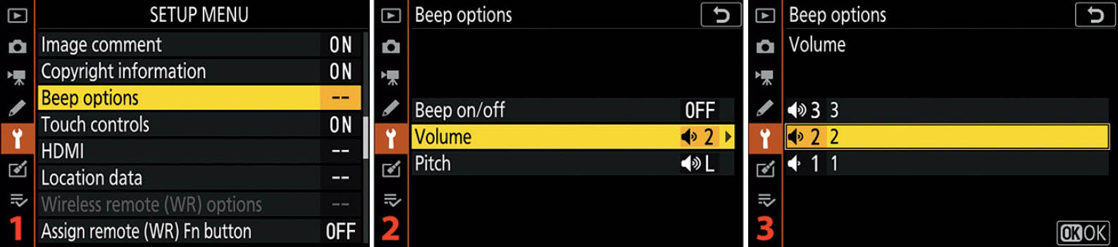
Figure 10.20B: Choosing a Volume level for the camera’s Beep
Use the following steps to select one of the Beep Volume choices:
- 1. Follow the screen flow shown in figure 10.20B, images 1 and 2 (Beep options > Volume), until you arrive at the third screen in the series.
- 2. Choose one of the three options from the list (1, 2, or 3). In figure 10.20B, image 3, Volume level 2 is selected (factory default). If you have Beep options > Beep on/off set to On, you will hear a sample beep for each volume level as you choose it. The level 1 beep is rather quiet, so you may not hear it well unless you hold your ear close to the camera, whereas the level 3 beep is relatively loud. Press the OK button or tap the option to lock in the setting.
Next, let’s consider the screens and steps to select a pitch for the beep.

Figure 10.20C: Choosing a Pitch for the camera’s Beep
Use the following steps to select a Beep Pitch:
- 1. Follow the screen flow shown in figure 10.20C, images 1 and 2 (Beep options > Pitch), until you arrive at the third screen in the series.
- 2. Choose one of the two options from the list (High or Low). In figure 10.20C, image 3, Low is selected. If you have Beep options > Beep on/off set to On, you will hear a sample beep in each pitch when you choose it. Press the OK button or tap the option to lock in the setting.
Settings Recommendation: I keep Beep turned Off on my Z6. If I were using my camera in a quiet area, why would I want it beeping and disturbing those around me? However, you might want the reassurance of hearing a beep when AF has been confirmed or when the Self-timer is counting down. If so, turn it on. The Self-timer lamp flashes during Self-timer operations, so I generally use that instead of Beep.
Touch Controls
The Nikon Z6 has a convenient touch-control capability that lets you use your fingertip to enter the names of various items, select touch controls on the Monitor, swipe from one picture or video to another when viewing them on the Monitor, and press Play on displayed videos.
The Touch controls function allows you to enable or disable the touch-control feature, as well as set the swipe (flick) direction for when you are viewing pictures. Let’s examine how to configure the two parts of the Touch controls system.
Enabling or Disabling the Touch Controls System
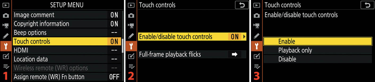
Figure 10.21A: Enabling or disabling the camera Touch controls system
Use the following steps to enable or disable the camera’s Touch controls system:
- 1. Follow the screen flow shown in figure 10.21A, images 1 and 2 (Touch controls > Enable/disable touch controls), until you arrive at the third screen in the series.
- 2. Select Enable to use all available touch controls, Playback only if you want to use touch controls only when viewing images/videos on the Monitor (Playback), or Disable if you do not want to use touch controls at all (figure 10.21A, image 3). Press the OK button or tap the option to lock in the setting. The factory default is Enable.
Settings Recommendation: I have been using the Touch controls system quite often as I work through the many functions it supports. I find it quite convenient when entering data, compared to fiddling around with physical buttons and pads.
The only gripe I have is that I would prefer a QWERTY keyboard layout instead of an alphabetical series of letters, just because I’m used to using that layout on my smartphone (texting). Why couldn’t Nikon make a keyboard that looks more like my iPhone’s keyboard, including the touch button locations and functionality, so that I (and you) don’t have to search for each character? Aren’t we all used to using tiny smartphone keyboards by now? Why have an Aa& touch button instead of ↑ and 123?
Otherwise, the Touch controls system works well and is easy to use. I think our smart cameras are finally joining the digital world, at least to some degree.
Changing Swipe (Flick) Direction for Viewing Images

Figure 10.21B: Setting the direction of the finger swipe when viewing images on the Monitor
Use the following steps to change the direction of the swipe used to scroll through pictures:
- 1. Follow the screen flow shown in figure 10.21B, images 1 and 2 (Touch controls > Full-frame playback flicks), until you arrive at the third screen in the series.
- 2. Select either Left←Right or Left→Right from the menu (figure 10.21B, image 3). Press the OK button or tap the option to lock in the setting.
Settings Recommendation: I’ve been scratching my head trying to figure out why someone would want the swipe (flick) to work in the opposite direction of what smartphone users have trained their muscle memory to expect. When I am swiping on my camera’s Monitor, I expect to see the next image by swiping from right to left, just like on my iPhone.
However, if you would prefer the swipe to work in the opposite direction, choosing Left→Right will fix you right up. Then, when you swipe right to left, the camera will display the previous picture instead of the next picture.
HDMI
HDMI (high-definition multimedia interface) allows you to display your images and videos on a high-definition television (HDTV), external video monitor, or computer monitor with an HDMI connection. You can also use the HDMI port to stream clean, 4K, 10-bit, 4:2:2, N-Log video to an external video recording device, such as one of the recorders found on www.Atomos.com.
You’ll need an HDMI Type-A to HDMI Type-C cable, which is not included with the camera but is available from many electronics stores. This cable is also known as a mini-HDMI–to–HDMI A/V HD cable.
Figure 10.22A gives you a closeup look at both ends of the cable. The smaller end (mini-HDMI Type-C) goes into the HDMI port under the rubber flap on your camera, and the other end (HDMI Type-A) plugs into your HD device.

Figure 10.22A: HDMI cable ends
The HDMI setting has two options—Output resolution and Advanced—which we will discuss next.
Output Resolution
You can select one of the following formats for output to your HDMI device, including external video recorders:
- Auto: This allows the camera to select the most appropriate format for displaying your image on the currently connected device.
- 2160p (progressive): 3840 × 2160 progressive UHD format
- 1080p (progressive): 1920 × 1080 progressive Full HD format
- 1080i (interlaced): 1920 × 1080 interlaced Full HD format
- 720p (progressive): 1280 × 720 progressive HD format
- 576p (progressive): 720 × 576 progressive SD format
- 480p (progressive): 640 × 480 progressive SD format

Figure 10.22B: Selecting an HDMI Output resolution
Use the following steps to select an Output resolution:
- 1. Follow the screen flow shown in figure 10.22B, images 1 and 2 (HDMI > Output resolution), until you arrive at the third screen in the series.
- 2. Select one of the six output resolutions or Auto (figure 10.22B, image 3). I chose 720p (progressive) as an example because it matches the output format of the external video capture device I use to capture images for this book. The camera offers resolutions from as low as old standard-definition television (SDTV) resolutions up to ultra-high definition 4K television (UHDTV), so it’s quite flexible! You might want to try Auto at first to see if the camera and display device will interface by themselves. If not, read the user’s manual for the display device to find out what output resolution works best with it, and set the camera accordingly. Press the OK button or tap the option to lock in your selection.
HDMI Output Resolution Setting – External versus Internal Video Recording
The Output resolution setting directly sets the HDMI output for an external recorder, such as a Ninja, Sumo, or Shogun by Atomos (www.Atomos.com). Older external Atomos video recorders, such as a Ninja-2, are limited to Full HD (1080p), whereas a newer Ninja V can record up to 4K UHD at 60 fps progressive (2160/60p). Currently, the Nikon Z6 is limited to 4K UHD at 30 fps progressive (2160/30p).
However, Output resolution does not affect the internal video recording capability of the camera, which ignores the HDMI Output resolution and instead relies on the resolution selected under Movie Shooting Menu > Frame size/frame rate or the i menu’s Frame size and rate/Image quality setting, when your camera’s Photo/movie selector switch is set to Movie.
Power Off Delay and the Standby Timer
The HDMI output you will use to send video to your external recorder has a default 30-second Power off delay to save battery charge, which means your camera will shut off after 30 seconds of recording, unless you extend the Power off delay. You should set the Standby timer (page 396) to a significantly longer timeout setting, such as 10 minutes, 30 minutes, or No limit.
Use the Custom Setting Menu > c Timers/AE lock > c3 Power off delay > Standby timer setting to lengthen the HDMI video stream timeout. Use a longer delay or No limit for the Standby timer setting.
Progressive versus Interlaced
What’s the difference between progressive and interlaced? Technically speaking, progressive video output displays the video frame starting with the top line and then draws the other lines until the entire frame is shown. The camera displays 2160 lines progressively from the top of what the imaging sensor captured to the bottom (lines 1, 2, 3, 4 . . . 2160).
Interlaced video output displays every even line from top to bottom, then comes back to the top and displays every odd line (lines 2, 4, 6, 8 . . . 2160; then 1, 3, 5, 7 . . . 2159).
Progressive output provides a higher-quality image with less flicker and a more cinematic look. Most of the HDMI Output resolution settings are for progressive output; however, Nikon has provided 1080i (interlaced) in case we need to use an interlaced output later.
Advanced
With the large variety of display and external recording devices available, your camera has to deal with all sorts of video standards. Here is a brief list of the controls available for modifying the HDMI video output:
- Output range: Controls how color is displayed on the receiving device. You can limit the RGB video output to a Limited range of 16 to 235, or a Full range of 0 to 255. Or you can select Auto to let the camera decide for you.
- External recording control: If you are using an external HDMI video recorder that will support the Atomos Open Protocol—such as the Atomos Shogun, Ninja, or Sumo series—you can control the external recorder with on-camera controls.
- Output data depth: You can choose from 8-bit or 10-bit output. The 10-bit selection is available in 4K only when the camera is connected by HDMI to an external Atomos recorder (firmware C2.00). The 8-bit selection will work for recording 4K video either to the internal memory card or an external recorder. The camera can use 10-bits when recording to the XQD card at 1080/30p or lower video resolutions only. This could change with a firmware update.
- N-Log setting: Tells the camera to output a lower-contrast, higher dynamic-range video signal that tends to preserve shadow and highlight detail. The contrast and color when using N-Log are even flatter than the Flat Picture Control. A videographer will need to “grade” (post-process) the video later, adjusting color saturation and contrast until an acceptable look has been set for the video.
- View assist: Provides a live preview of the N-Log affect on the video recording. The colors may differ slightly between the camera’s Monitor and the actual video. However, this preview has no effect on the video recording. It is merely informational, allowing you to make adjustments if needed.
Let’s examine each setting on the Advanced menu in more detail.
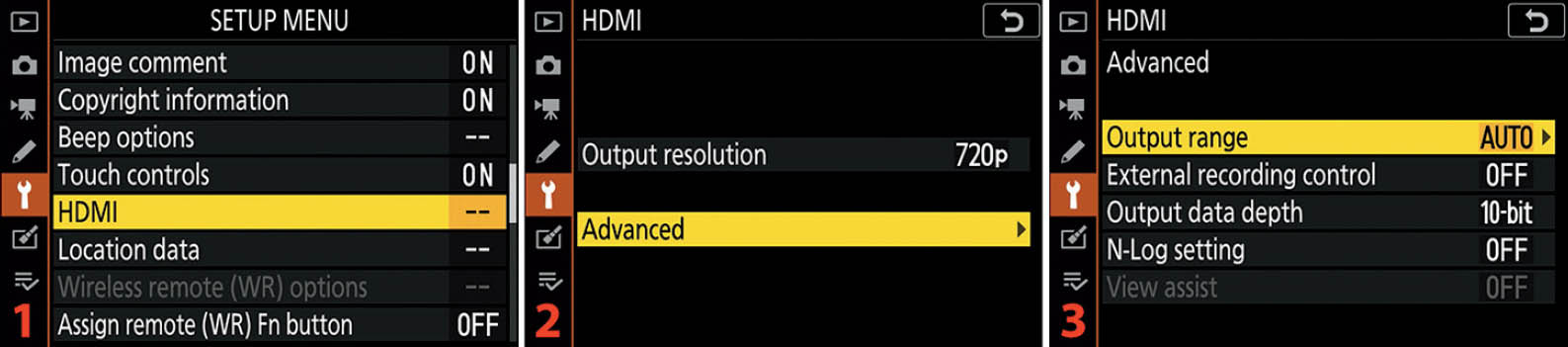
Figure 10.22C: Using Advanced HDMI settings
Use the following steps to open the Advanced menu (figure 10.22C):
- 1. Follow the screen flow shown in figure 10.22C, images 1 and 2 (HDMI > Advanced), until you arrive at the third screen in the series.
- 2. Select one of the five settings from the Advanced menu and scroll to the right (figure 10.22C, image 3).
- 3. Refer to figures 10.22D through 10.22K for details on the configuration of each Advanced item.
Output Range
Output range allows you to adjust the level of colors sent to a recording or display device. When you are outputting video to a device, such as an HDTV or recorder, the device may not accept normal Full range RGB with a color range of 0 to 255 correctly. Some devices accept only Limited range RGB input in the range of 16 to 235 color levels (YCbCr). If you try to send Full range RGB video output to a Limited range YCbCr device, you may end up with washed-out, grayish blacks and blown-out, featureless whites.
The solution is to match the correct output to the correct device type. If you see the problems just described when the camera is set to Full range (RGB), try the Limited range (YCbCr) setting instead. Or, you could try the Auto setting to see if the camera can detect what the display or recording device requires.

Figure 10.22D: Selecting an Output range
Use the following steps to select Full range or Limited range output (figure 10.22D continues from figure 10.22C):
- 1. Select Output range from the Advanced menu and scroll to the right (figure 10.22D, image 1).
- 2. Choose Auto, Limited range, or Full range from the Output range menu. Auto (factory default) is selected in figure 10.22D, image 2. Press the OK button or tap the option to select the Output range.
Settings Recommendation: Please spend some time familiarizing yourself with the features of this function. The Z6 camera has enhanced video output compared to its predecessors. Therefore, if you have not been fond of video with an HD-SLR in the past, you may want to reconsider now that you are using the mirrorless Nikon Z6. It’s a portable home movie studio, with full UHD (4K) commercial capabilities!
External Recording Control
The External recording control setting allows you to control an Atomos external recorder (e.g., Ninja V) directly from your camera. You can start and stop recording on the external recorder by pressing the camera’s Movie record button when the Z6 and recorder are connected by an HDMI cable.
Let’s examine the Input tab on an Atomos Ninja V external recorder to see how to let the camera remotely control when the recorder starts and stops recording (figure 10.22E). We will need to set an HDMI Trigger.
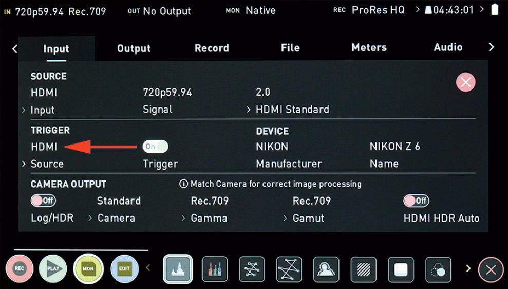
Figure 10.22E: Setting the Trigger to HDMI on an Atomos Ninja V external recorder
Figure 10.22E: You must set the Trigger under the Input tab of the Atomos external recorder to HDMI. On the Atomos Ninja V external recorder screen shown in figure 10.22E, you will touch where the red arrow is pointing, multiple times, until HDMI appears. Make sure the little touch slider switch is set to On. Now, when you press the camera’s Movie record button, the external recorder will automatically start receiving and recording the HDMI video output from your camera. Make sure you have selected an appropriate HDMI Source Output resolution so that the external recorder will record at the correct video resolution (e.g., 720p, 1080p, 2160p, see figure 10.22B on page 509).
Now that we have looked at a Ninja V screen, and configured the HDMI Trigger, let’s discuss the screens you will see on your Z6 when you are using this feature.

Figure 10.22F: External recording control symbols
The following paragraphs examine what the Movie recording symbols mean:
Figure 10.22F, image 1: There are several symbols you will see on your camera screen, according to how you are recording video. The Movie record screen will display a small standby (→STBY) symbol when the external recorder and camera are ready to start recording (figure 10.22E, image 1). Immediately to the left of the small →STBY symbol is a blank spot with no other symbols (compare to figure 10.22F, image 3, blue arrow). This is significant! The fact that there are no symbols, strangely enough, means that the camera is ready to send video to the external recorder and record video to the camera’s memory card, at the same time. This will make more sense when we discuss figure 10.22F, image 3. When you press the Movie record button on the top of the camera, the external recorder and memory card will record video, and the next screen (image 2) will show. There are some limitations when recording to both devices as the same time, as discussed in the note below.
Note: In this and future discussions of recording video to both an external recorder and the internal XQD card at the same time, please remember the following information: The internal XQD card cannot accept 10-bit video at 4K UHD (2160p) resolution (using firmware C1.02); therefore, recording to both an external recorder and the internal XQD card at the same time requires using a video resolution of 1080/30p or below only. The HDMI > Advanced > Output data depth setting (next subsection) can be set to 8-bit or 10-bit, and then the external recorder and internal XQD card will receive video at the chosen resolution. In other words, recording in 4K resolution (2160p) to both the external recorder and the XQD card is not possible with camera firmware C2.00. That could change with a firmware update.
Figure 10.22F, image 2: When you have started recording video by pressing the Movie record button, the camera will display two symbols. First you will see the ![]() REC symbol (blue arrow). This
REC symbol (blue arrow). This ![]() REC symbol means the camera is recording video to its XQD memory card. To the right of the blue arrow’s
REC symbol means the camera is recording video to its XQD memory card. To the right of the blue arrow’s ![]() REC symbol, you will see a tiny recorder screen symbol with an arrow pointing at a smaller →REC symbol (red arrow). Where the blue arrow’s
REC symbol, you will see a tiny recorder screen symbol with an arrow pointing at a smaller →REC symbol (red arrow). Where the blue arrow’s ![]() REC symbol means the camera is recording video, the red arrow’s →REC symbol means the external video recorder is now receiving video too, and should be recording it if the camera and the external recorder are connected properly.
REC symbol means the camera is recording video, the red arrow’s →REC symbol means the external video recorder is now receiving video too, and should be recording it if the camera and the external recorder are connected properly.
Figure 10.22F, image 3: When you have the external recorder prepared to receive video, but have removed the camera’s XQD memory card to prevent recording to it too, you will see the symbols shown at the blue arrow. The top symbol is a REC symbol with a slash through it and the lower symbol is a red memory card symbol with a slash through it (blue arrow). These two symbols signify that the camera will not record video internally, but will send the video stream to the external recorder only, when you press the Movie record button. The →STBY symbol (red arrow) means that the camera is awaiting your command to start sending video to the external recorder and that the external recorder is awaiting the Movie record button press to Trigger (see figure 10.22E) the recording.
Figure 10.22F, image 4: When you have pressed the Movie record button, and thereby triggered the external recorder, the →REC symbol shown at the red arrow means that the camera is sending a video stream to the external video recorder through the HDMI port. The lack of the ![]() REC symbol means the internal XQD memory card is not receiving video.
REC symbol means the internal XQD memory card is not receiving video.
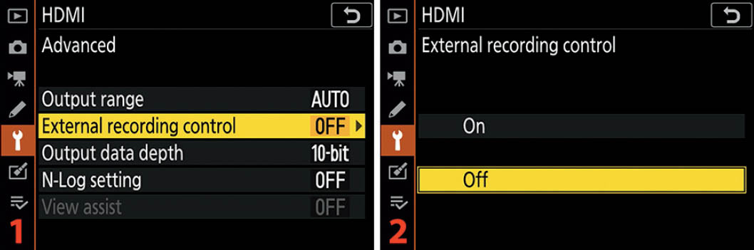
Figure 10.22G: Enabling or disabling External recording control
Use the following steps to enable or disable the External recording control (figure 10.22G continues from figure 10.22C):
- 1. Choose External recording control from the HDMI > Advanced menu and scroll to the right (figure 10.22G, image 1).
- 2. Highlight On or Off and press the OK button or tap the option to enable or disable the External recording control (figure 10.22G, image 2).
Settings Recommendation: If you own an Atomos external recorder, it is a good idea to turn the External recording control on. If you do not have an external recorder, you can leave it off and safely ignore this setting.
Output Data Depth
The Output data depth setting allows you to choose a bit depth for your video recordings. You can choose from 8-bit (16.7 million colors) or 10-bit (1.07 billion colors). The 10-bit 4K UHD (2160p) recording can be done with compatible external recorders only, such as the newer recorders in the Shogun, Ninja, or Sumo series by Atomos.
The camera’s internal memory card can accept 8-bit video in all resolutions, including 4K, but can accept 10-bit video only at resolutions of Full HD (1080/30p) or below. None of the 1080/120p, 1080/100p, or slow-motion settings are available for 10-bit either. Again, this is based on firmware C2.00, and 10-bit 4K video (and the other settings mentioned) could become available for recording to the XQD card if Nikon decides to update the camera’s firmware.
If you have 10-bit 4K selected, and you try to record to the XQD card when hooked up to an external recorder, the camera will disable video recording to the memory card. If you attempt to record 10-bit 4K directly to the XQD card alone, the Z6 will automatically switch to 8-bit recording, regardless of your having selected 10-bit.

Figure 10.22H: Selecting 8-bit or 10-bit video recording
Use the following steps to select 8-bit or 10-bit video recording (figure 10.22H continues from figure 10.22C):
- 1. Choose Output data depth from the HDMI > Advanced menu and scroll to the right (figure 10.22H, image 1).
- 2. Highlight 8 bit (default) or 10 bit and press the OK button or tap the option with your fingertip (figure 10.22H, image 2). Whichever mode you select will change the HDMI video output to that bit level.
- 3. If you select 10 bit, an informational screen will pop up (figure 10.22H, image 3), informing you that only certain Frame size/frame rates can be used with 10 bit recording to the XQD card (as previously discussed).
N-Log Setting
N-Log setting causes the camera to output a low-contrast, high-dynamic-range HDMI video signal that preserves shadow and highlight detail. You will need to grade the video after the fact, making adjustments to color saturation and contrast in an app—such as Final Cut Pro or Adobe Premier Pro—until you are happy with how the video looks. Use N-Log only if you plan on grading the video later in a computer program. Otherwise, your video will appear washed out and will have pale colors.

Figure 10.22I: N-Log setting: Off and On (cannot record to card)
In figure 10.22I you can see how the camera outputs a video signal with the Neutral Picture Control set (image 1), compared to using N-Log (image 2). These two screens were captured from the display of an Atomos Ninja V, with View assist (next subsection) enabled. Now let’s consider how to enable and disable N-Log.

Figure 10.22J: Enabling or disabling N-Log output over HDMI
Use the following steps to enable or disable N-Log, with the understanding that N-Log cannot currently be recorded to the XQD memory card (firmware C2.00), and instead must be output through the HDMI port to an external recorder (figure 10.22J continues from figure 10.22C):
- 1. Choose N-Log setting from the HDMI > Advanced menu and scroll to the right (figure 10.22J, image 1).
- 2. Highlight Off or On (cannot record to card) and press the OK button or tap the option to select it. Select Off unless you plan to send video to an external HDMI recorder. The camera will not record video to the XQD memory card when N-Log setting is enabled! If you are prepared to record video on an external recorder and you will grade the video later in software, then select On (cannot record to card) instead.
View Assist
The View assist setting provides a live preview of how N-Log setting affects a recorded video. The colors may differ slightly between the camera’s Monitor and the actual video. This is merely a preview and has no effect on the video recording. It is for informational purposes only, allowing you the opportunity to make adjustments.

Figure 10.22K: Enabling or disabling the View assist setting
Use the following steps to enable or disable View assist for a live preview of N-Log video (figure 10.22K continues from figure 10.22C):
- 1. Choose View assist from the HDMI > Advanced menu and scroll to the right (figure 10.22K, image 1).
- 2. Highlight On or Off and press the OK button or tap the option to lock it in (figure 10.22K, image 2).
Settings Recommendation: I enjoy the live preview aspect of View assist and leave it on when I am sending N-Log video to my Ninja V external recorder. If you have no external recorder you can safely leave this setting at Off.
Location Data
The Location data function allows you to geotag your images with global positioning system (GPS) location data. It provides an easy-to-use interface for various GPS and smart devices.
Now when you shoot a spectacular travel image, you can rest assured that you’ll be able to find that exact spot next year. With the Nikon GP-1 or GP-1A GPS units (or an aftermarket brand), or your smart device using SnapBridge, the Z6 will record some or all of the following GPS information into the metadata of each image:
- Latitude
- Longitude
- Altitude
- Heading (aftermarket only)
- UTC (time)
Using a Smart Device for GPS
The Nikon Z6 allows you to pull GPS data from your smart device (e.g., your smartphone) and automatically embed that location information in the metadata of your image(s). To use the SnapBridge app to transfer GPS data to your Z6, the following services must be enabled:
On the Smart Device
- Bluetooth: Enable Bluetooth under your smart device’s settings menu.
- Location services: In order for your smartphone to use its built-in GPS system, you must have Location data enabled.
- SnapBridge: The Nikon Snapbridge app must be installed on your smartphone and already configured to communicate with your camera if you want to use Snapbridge to geotag your images. See the heading Connect to Smart Device later in this chapter (page 528).
On the Nikon Z6
- Bluetooth: Use the following function to enable Bluetooth on your camera: Setup Menu > Connect to smart device > Pairing (Bluetooth) > Bluetooth connection. See Bluetooth Connection under the heading Connect to Smart Device later in this chapter (page 534).
- Location data: Using the settings discussed in this chapter subsection, you must prepare Location data use, including SnapBridge’s Synchronize location data (figure 10.23A). You will find the Location data timer at the following location: Setup Menu > Location data > Standby timer.
Let’s examine how to enable Synchronize location data under SnapBridge so that you can embed location data in your images.

Figure 10.23A: Smartphone SnapBridge app screens for Synchronize location data
Use the following steps to enable location data synchronization between your smart device and the Z6:
- 1. Open your already connected SnapBridge app and touch the Auto link selection (figure 10.23A, image 1, red arrow). If your app and camera are not yet paired, see Connect to Smart Device on page 528 for information on pairing the camera and the SnapBridge app.
- 2. The Synchronize location data selection point is shown at the red arrow on right side of the SnapBridge screen (figure 10.23A, image 2, red arrow). Touch the little round circle, which will change the background color of the circle from black to yellow and add a check mark. You will see a popup screen letting you know that it may take a few minutes for your smart device to obtain valid GPS data (not shown).
- 3. When the SnapBridge app (your smart device) has synchronized with GPS satellites, you will see your current GPS location under the Synchronize location data label (figure 10.23A, image 3, red arrow). Once you enable Location data on your smart device, and it has valid GPS data, the data will automatically be fed to the camera—via Bluetooth—for embedding in your image metadata. The connection will automatically time out to save battery when the camera is not in range; when you set the camera to Airplane mode; or when you disable Bluetooth.
The Bluetooth connection with SnapBridge will use additional battery power, so it’s a good idea to have extra batteries available when you’re using SnapBridge for GPS. Also, your smart device will use up its battery charge more quickly.
Warning: Please be aware that others can determine the location of your shared pictures when Synchronize location data is enabled. If you are taking family pictures, especially of children, and you use geotagged pictures, those who download the pictures from social media sites (e.g., Facebook, Instagram) can examine the image metadata and will be able to determine exactly where the picture was taken. Maybe it’s not a good idea to upload geotagged pictures of your kids, grandkids, or valuables if the pictures were taken at home.
Note: You may want to enable the Synchronize clocks setting (just above Synchronize location data on the SnapBridge screen shown in figure 10.23A, images 2 and 3). When the Synchronize clocks setting is enabled, the Z6 can embed time and date information received from the smart device for each picture taken.
Standby Timer
Figure 10.23B shows the screens used to set the camera to stay on the entire time an external GPS is connected, or shut down after the Standby timer expires.
The Setup Menu > Location data setting also has a subsetting named Standby timer, which can override the use of the Standby timer setting in Custom Setting Menu > c Timers/AE lock > c3 Power off delay.
The Custom setting c3 Standby timer function is for all aspects of the camera. The Setup Menu’s Location data Standby timer subsetting applies only to an attached GPS unit. Enable or disable Setup Menu > Location data > Standby timer according to the information in the following list:
- Enable (default): The meter turns off after the Custom Setting Menu > c Timers/AE lock > c3 Power off delay > Standby timer delay expires (the default is 30 seconds). GPS data will be recorded only when the exposure meter is active, so allow some time for the external GPS unit, powered by the camera, to reacquire a satellite signal before taking a picture. This is hard to do when Standby timer is set to the default 30 seconds. You pretty much have to stand around with your finger on the Shutter-release button trying to keep the meter active. I suggest using Disable.
- Disable: The exposure meter stays on the entire time an external GPS unit is connected. As long as you have a good GPS signal, you will be able to record GPS data at any time. This is the preferred setting for using the GPS for continuous shooting. It does use extra battery life, so you may want to carry multiple batteries if you’re going to shoot all day. Turn the camera off between locations.

Figure 10.23B: Setting an Standby timer delay for GPS usage
Here are the steps to configure the Standby timer delay:
- 1. Follow the screen flow shown in figure 10.23B, images 1 and 2 (Location data > Standby timer), until you arrive at the third screen in the series.
- 2. Select Enable or Disable (figure 10.23B, image 3). Use Disable for more reliable GPS usage, with somewhat greater battery drain. It is a good idea to carry multiple batteries if you are shooting all day with a Nikon GP-1, GP-1A, or an aftermarket GPS unit attached. Even the SnapBridge Bluetooth connection will use up extra battery charge. Press the OK button or tap the option to lock in the setting.
Position
When an external GPS unit is attached to your Z6, or the SnapBridge app and your camera are paired, with Synchronize location data enabled, the Position screen shows the GPS location data being detected by the camera (figure 10.23C). If your GPS unit is not attached to your camera, or SnapBridge is not communicating, the Position selection will be grayed out.
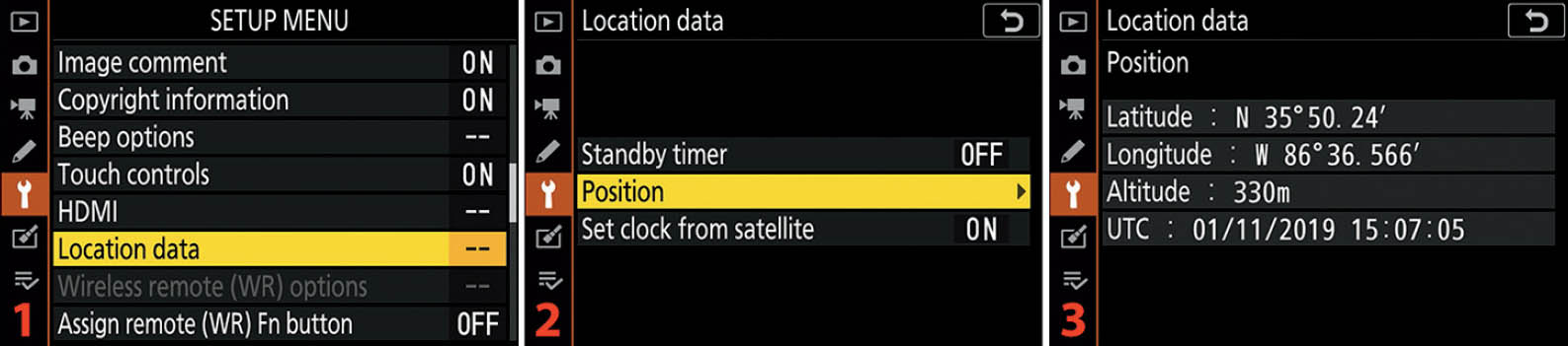
Figure 10.23C: GPS Position information screen
Use these steps to examine the Location data Position screen:
- 1. Follow the screen flow shown in figure 10.23C, images 1 and 2 (Location data > Position), until you arrive at the third screen in the series.
- 2. Examine the Position screen to see the four or five pieces of GPS satellite data (figure 10.23C, image 3). Notice that my SnapBridge/Z6 connection did not give me Heading information, nor would my Accessory shoe–mounted Nikon GP-1 GPS unit. Some aftermarket GPS units will give you Heading information, as discussed previously.
When the camera establishes communication with your GPS unit or SnapBridge, a couple of things will happen:
- Position information appears on the Position screen (figure 10.23C, image 3).
- An additional data information display screen will be displayed when you are using the Playback button to review images captured while the GPS was active (figure 10.23D). You can press up or down with the Multi selector pad to scroll through the image data screens on the Monitor. One of the data screens will be similar to the screen shown in figure 10.23D, which is a picture of the GPS position screen for a picture I took of a bare winter tree.

Figure 10.23D: Playback GPS position screen
Set Clock from Satellite
The Set clock from satellite function allows the Z6 to maintain accurate time by querying the GPS satellite to set the camera’s clock. If you use GPS a lot, you might want to leave this on. The clock in the Nikon Z6 is not as accurate as a wristwatch, for instance, and tends to lose accuracy more quickly. It’s a good idea to reset the camera’s clock from time to time. This is an easy way to accomplish that for GPS users.

Figure 10.23E: Using GPS to set the camera’s clock
Here are the steps to enable Set clock from satellite:
- 1. Follow the screen flow shown in figure 10.23E, images 1 and 2 (Location data > Set clock from satellite), until you arrive at the third screen in the series.
- 2. Choose Yes to enable the setting, and the GPS unit will be used to obtain a more accurate time setting, or choose No if you don’t want to set the camera’s clock from the GPS data (figure 10.23E, image 3). Press the OK button or tap the option to save the setting.
Using an External GPS Unit

Figure 10.23F: Nikon Z6 with a Nikon GP-1 GPS unit (1), MC-DC2 remote release cable (2), and GP1-CA90 interface cable (3)
The GP1-CA10 cable will interface with Nikon cameras that have a 10-pin port on the body, including the following Nikon cameras: D200, D300, D300S, D500, D700, D800, D800E, D810, D850, D2X, D3, D3S, D3X, D4, D4S, and D5.
The GP-1 GPS unit also comes with a GP1-CA90 cable to interface with Nikon cameras, including the following models: D3xxx, D5xxx, D7xxx, D600, D610, D750, Df, Z7, and Z6. Therefore, it is a useful device for almost any of your Nikons.
You can also get an optional Nikon MC-DC2 remote release cable that plugs directly into the GP-1 GPS unit for hands-off, vibration-free photography. The MC-DC2 remote release cable can be used to fire the shutter on any Nikon DSLR that can interface with the GP-1 or GP-1A GPS unit. You can see the MC-DC2 remote release cable on the left side of the camera in figure 10.23F. It is plugged into the GP-1 GPS unit on the opposite side of where the GP1-CA90 cable plugs in. The mentioned cables are compatible with both the Nikon GP-1 and GP-1A GPS units.
Nikon GP-1 GPS satellite connection information: The rear LED light on the Nikon GP-1 GPS unit will blink red while the GPS is acquiring satellites; blink green when the GPS is locked onto two satellites; and shine solid green when the GPS is locked onto at least three satellites. Allow a few seconds for the GPS to acquire satellites when the camera has been turned off.
If you are a significant distance from where you last used the GP-1 GPS unit, it may require up to a minute or two to acquire a satellite lock. Once the GP-1 has a local satellite lock and you turn the camera off, the GPS unit will reacquire the signal in just a few seconds when the camera is turned back on.
Aftermarket GPS Unit Information: The Nikon GP-1 and GP-1A GPS units do not have a built-in digital compass, so they will not report heading information to the camera. Other GPS units do have the built-in compass and will report the heading. If that is important to you, please investigate the Geotagger GMAX GPS unit at http://www.solmeta.com.
Settings Recommendation: Get the Nikon GP-1 or GP-1A GPS unit from one of many vendors, or get the Solmeta GMAX-GD GPS from Amazon.com. Either unit is easy to use and has all the cables you need for interfacing with your camera.
If you choose one of the Nikon GPS units, the only other cable you’ll need to buy is the optional MC-DC2 shutter-release cable (coiled on the left in figure 10.23F). I use the tiny Nikon GP-1 GPS unit constantly when I’m shooting nature images so that I can remember where to return in the future. After you start using a GPS unit, you’ll find it hard to stop.
If you prefer to use a smart device for GPS, you will need to learn how to configure and use the SnapBridge app, which can be more battery intensive than using an external GPS unit. For occasional GPS use, the smartphone is fine, but for extensive GPS use, I would select an external GPS unit. An external GPS unit’s physical connection may use less battery power than the SnapBridge/Z6 Bluetooth connection. Of course, you likely already have a smartphone and SnapBridge is free, so why not try it first and see if it works well for you.
Wireless Remote (WR) Options
The Wireless remote (WR) options function lets you adjust settings for optional WR-R10 Wireless Remote Controllers. The WR-R10 plugs into the Accessory port on the side of the camera and allows you to control multiple banks of remote (slave) flash units.
There are two settings in the Wireless remote (WR) options function:
- LED Lamp: The WR-R10 Wireless Remote Controller has two LED lamps on it that blink frequently as you use the device to control remote, radio-controlled, Speedlight flash units. In some instances, the blinking lights may be unwanted, so Nikon gives you the ability to turn them off and on as needed. The WR-R10 will work normally when the LEDs are turned off; it just won’t signal you with blinking lights.
- Link mode: Remote devices controlled by a WR-R10 Wireless Remote Controller can be paired with the controller in two different ways. The default method requires you to press the Pairing button on the WR-R10 until a Link light is illuminated on the remote device. This method is somewhat insecure since anyone with a master WR-R10 can control any slave device configured to be controlled by a WR-R10. Therefore, Nikon has provided a secondary method for pairing a master WR-R10 with its remote slave units, which requires you to type in a PIN code on each slave device.
Let’s examine how to configure each of these two settings.
LED Lamp
The LED lamps default to on, so they will blink regularly while the WR-R10 is in use. If you find this to be distracting, you can disable the LEDs. Let’s see how.
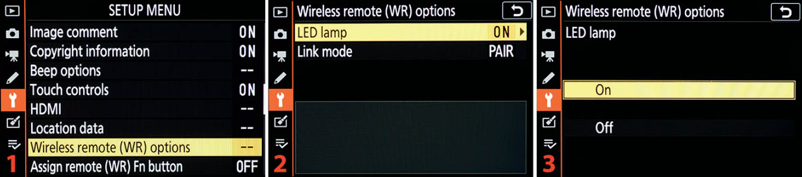
Figure 10.24A: Enable or disable the WR-R10 LED lamp
Use the following steps to enable or disable the WR-R10 LED lamps:
- 1. Follow the screen flow shown in figure 10.24A, images 1 and 2 (Wireless remote (WR) options > LED lamp), until you arrive at the third screen in the series.
- 2. Choose On or Off to control whether the LED lamps on the WR-R10 blink during use (figure 10.24A, image 3). Press the OK Button or tap the option to lock in the setting.
Settings Recommendation: When I am shooting in a studio environment and creating product shots, I do not mind if the lights blink on my WR-R10 Wireless Remote Controller. In fact, I find the blinking lights reassuring.
However, during a wedding, when I have a remote flash positioned for better lighting, I do not want blinking LED lights on my WR-R10 distracting the wedding party and proceedings, so I disable them. It is easy to turn them on and off, so do so when you need to for your style of photography.
Link Mode
If you are shooting in environments where there may be other photographers using WR-R10 units and you worry about one of them trying to take control of your remote slave units, you may want to use the PIN method to pair with your slave units.

Figure 10.24B: Setting the style of Link mode pairing
Use the following steps to select the style of master/remote pairing you prefer when using your WR-R10 Wireless Remote Controller:
- 1. Follow the screen flow shown in figure 10.24B, images 1 and 2 (Wireless remote (WR) options > Link mode), until you arrive at the third screen in the series.
- 2. Choose one of the following link modes:
- Pairing: If you choose Pairing (figure 10.24B, image 3), highlight it and press the OK button or tap the option to lock in the setting. You will now need to set your slave units to use Pairing and then use the Pairing button on your WR-R10 to make a link. Refer to the instructions included with the WR-R10 and the remote flash units (e.g., SB-5000) to learn how to use the Pairing button(s) and remote Link lights.
- PIN: If you choose PIN (figure 10.24B, image 3), you will need to create a four-digit numerical pin number, from 0000 to 9999. Scroll to the right and tap the little yellow pointers on the screen or use the Multi selector pad to scroll up or down on each number selection box until you have created your PIN (figure 10.24B, image 4). Press the OK button to lock in the PIN setting. The PIN you entered will now appear on the Wireless remote (WR) options screen (figure 10.24C) so that you can access it easily in case you forget it.
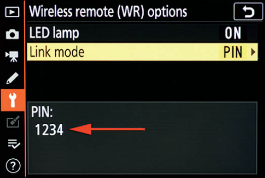
Figure 10.24C: PIN code available on camera screen
Settings Recommendation: I normally use the PAIR (Pairing) setting because I work by myself most of the time. In addition to configuring the WR-R10, you will need to configure each remote unit. Therefore, think carefully about how you will be working with your master/remote units. If you are shooting in an environment where there could be people who would like to aggravate you by taking over your remote units with their WR-R10, why not set up a PIN instead of using the Pairing button?
Assign Remote (WR) Fn Button
The Assign remote (WR) Fn button function allows you to program the camera to respond in various ways when you press the Fn button on an optional remote controller (one that has an Fn button, of course). You can assign 10 different functions to the controller’s Fn button. First let’s see an alphabetical list of the settings:
- AE/AF lock
- AE lock only
- AE lock (Reset on release)
- AF lock only
- AF-ON
- [Flash] Disable/enable
- FV lock
- + NEF (RAW)
- None
- Preview
Because this function is so similar to many other assignment functions we have already considered over the last few chapters, we will examine how to assign the Fn1 button, but will not discuss what each assignment function does.
If you do not know what a particular function does, please refer to the detailed list of functionality for each option under Custom Setting Menu > f Controls > f2 Custom control assignment (page 423).
Let’s see how to assign a function to the Fn button on your remote controller.

Figure 10.25: Assigning a function to the remote controller’s Fn button
Use the following steps to select a function for an optional remote controller’s Fn button:
- 1. Choose Assign remote (WR) Fn button from the Setup Menu and scroll to the right (figure 10.25, image 1).
- 2. Select one of the 10 available functions (figure 10.25, image 2) and press the OK button or tap the option to make the Fn button assignment.
Settings Recommendation: As a nature and event photographer, I have rarely used this Assign remote (WR) Fn button function. The camera defaults to +NEF (RAW) as the assignment for the remote Fn button. If you have a wireless remote and you think you might use this extra Fn button as part of its use, and +NEF (RAW) is not useful to you, then choose from the list of 10 functions the one you would most likely use.
Airplane Mode
Airplane mode in the Z6 works in a similar way to the airplane mode in your smart device. When you enable Airplane mode, the camera will turn off all radio transmissions of any type from within the camera body, including Wi-Fi and Bluetooth.
However, if you have a WR-R10 or another wireless controller plugged into the 10-pin port, it will continue sending and receiving radio signals. Unplug any external wireless controllers to have true radio silence.

Figure 10.26: Enabling or disabling Airplane mode (no radio signals)
Use these steps to enable or disable Airplane mode in the Nikon Z6:
- 1. Choose Airplane mode from the Setup Menu and scroll to the right (figure 10.26, image 1).
- 2. Choose Enable to turn on Airplane mode and cause the camera to go into radio-silence mode, or Disable to turn Airplane mode off and allow the camera to send and receive radio signals (figure 10.26, image 2). Press the OK button or tap the option to lock in the setting.
Settings Recommendation: When I go out into the wild to shoot my nature images, I often set the camera to Airplane mode. In fact, I keep it as one of the options under My Menu (page 600) so that I can access it quickly. Sometimes, I need all the battery power I can get, and Airplane mode conserves battery.
Connect to Smart Device
The Connect to smart device function is the core function to enable Bluetooth and Wi-Fi connectivity with your Nikon SnapBridge app. This connection explanation is based on interfacing a Nikon Z6 with an iPhone 7 Plus smartphone, running the Apple iOS 12.1.2 operating system.
The SnapBridge app is available for both Android and iOS. The actual SnapBridge screens vary somewhat in appearance per smartphone operating system. However, they work in basically the same way. Whether using Android or iOS, you will find it fairly easy to make the camera and smart device connection.
Note: All SnapBridge and camera screens shown in this Connect to Smart Device section are from interfacing with my Z7. However, Nikon Z6 screens are the same.
Bluetooth versus Wi-Fi
The Bluetooth connection (page 534) allows your smart device to communicate directly with your Nikon Z6 using low-energy Bluetooth (BLE). Your Nikon Z6 and your smart device set up their own private Bluetooth network. Your smart device must be compatible with Bluetooth 4.0 and have BLE capability (most devices up to three or four years old work with BLE).
The Wi-Fi connection (page 537) sets up an “ad hoc” wireless network between the Nikon Z6 and the SnapBridge app on your smart device. The connection does not depend on any other Wi-Fi networks that may or may not be available in the area. It is a standalone, private connection between your camera and smart device.
The Nikon Z6 does not work with Nikon’s older WMU app. The camera is designed to connect only with smart devices running the SnapBridge app.
Now let’s discuss how to connect your Z6 to your smart device by using the SnapBridge app.
Pairing the Z6 with Your Smart Device
To make and use the connection (pairing) between your camera and smart device, you will need to use multiple radio-based services, including Bluetooth and Wi-Fi. Before you attempt to make the connection, you must enable Bluetooth and Wi-Fi on your smart device (e.g., iPhone). And if you want to use GPS location information (page 518), enable Location services.
The process of pairing the two devices is relatively easy. Let’s step through the screens and steps used to make a connection between your Z6 and a smart device (SnapBridge app):
- 1. Download and install SnapBridge on your smart device. You will find SnapBridge in the Apple App Store for iOS and in the Google Play Store for Android. Once installed, do not open the app until instructed. First we need to get the camera ready to communicate with the SnapBridge app.

Figure 10.27A: Pairing your camera and smart device (initial steps on the camera)
- 2. Choose the Connect to smart device function from the Setup Menu and scroll to the right (figure 10.27A, image 1).
- 3. Select Pairing (Bluetooth) and scroll to the right (figure 10.27A, image 2).
- 4. Highlight Start pairing and press the OK button or tap the option with your fingertip (figure 10.27A, image 3).
- 5. The Pairing (Bluetooth) screen will be displayed with a special code for your Camera (e.g., Z_7_3001781). The code uses your camera’s serial number as its last seven digits and is used as a Bluetooth connection name in your smart device. Once you have this screen (figure 10.27A, image 4) on the camera, it is time to open the SnapBridge app.

Figure 10.27B: Pairing the camera and smart device (initial steps on SnapBridge)
- 6. The initial SnapBridge screen in your smart device has a menu available under the three dots (figure 10.27B, image 1, red arrow). Tap on the dots and the menu will open.
- 7. Tap the Add camera selection on the SnapBridge menu (figure 10.27B, image 2). This will open the camera-type selection menu. (Note: If the SnapBridge app detects the camera immediately after you tap the Add camera button in image 2, it may skip the screens shown in figure 10.27B, image 3, and figure 10.27C, image 1, and go directly to the screen shown in figure 10.27C, image 2. If the Z6 skips these screens, continue with step 10; otherwise, move on to step 10.)
- 8. Select a camera type from the menu. In this case you will tap mirrorless camera (figure 10.27B, image 3).

Figure 10.27C: Camera located, now let’s connect
- 9. Once the SnapBridge app senses the camera, it will show a line similar to the one seen in figure 10.27C, image 1, red arrow. This line is the camera’s name followed by the camera’s serial number (e.g., Z7_3001781). Tap the camera name line to select it.
- 10. The SnapBridge app will provide instructions on proceeding with the connection and will wait for you to tap the Understood button at the bottom of the screen shown in figure 10.27C, image 2. When you are ready, tap the Understood button.
- 11. The SnapBridge app will now take a moment to connect to the camera via Bluetooth. You will see a screen that says Connecting to camera (figure 10.27C, image 3). Wait a moment until the SnapBridge app finds the camera. Starting with step 13, the steps are time sensitive, so read them over carefully before proceeding. Otherwise, while you are reading the steps the camera and SnapBridge app may time out in trying to communicate by Bluetooth, and you will have to start over. Once you start the process, if you do not complete it within about 10 seconds, the timeout will occur.

Figure 10.27D: Searching for the camera and listing it for connection
- 12. When you see the Select An Accessory screen in figure 10.27D, image 1, the app has located the camera and is reading its internal information. At first the list may be blank, with no camera listed. Be patient while the app and the camera communicate; it may take several seconds. When the app has read the camera’s internal information, it will show you the camera name and serial number in the list (e.g., Z6_3001781). Tap the camera name line and wait a moment until both the camera and SnapBridge app display the following screens. You must follow the next step quickly and in the exact order discussed.
- 13. As figure 10.27D, images 2 (SnapBridge) and 3 (camera) show, the SnapBridge app and camera are displaying the same Auth. code number (e.g., 400899). Complete the next two actions within a few seconds: [1] Tap the Pair button on the SnapBridge app (figure 10.27D, image 2); [2] Tap the OK control on the camera Setup Menu screen (figure 10.27D, image 3). This causes the SnapBridge app and the camera to enter into the active pairing phase.

Figure 10.27E: Final handshaking and pairing complete
- 14. The camera and SnapBridge app will do some final handshaking while another Connecting to camera screen shows (figure 10.27E, image 1).
- 15. When the pairing is complete within the SnapBridge app, you will see the Pairing complete and Connected to camera screen (figure 10.27E, image 2).
- 16. In the meantime, the camera will rapidly display a series of screens (figure 10.27E, images 3A, 3B, and 3C). The first pairing screen will say Establishing connection (image 3A). The second pairing screen will say Pairing complete (image 3B). Then the camera will return to the Connect to smart device screen. This final screen will show the name of your smart device (e.g., DarrellsiPhone7Plu) and Connected to smart device (image 3C). At this point the camera and SnapBridge app are officially paired. Tap the OK button on the SnapBridge screen (figure 10.27E, image 2).
Congratulations! You got through the pairing process successfully. The camera and app are now ready to transfer images. If the pairing failed, try again by starting over with the following steps:
- Turn the camera off and back on to clear memory
- Shut down and restart the SnapBridge app
- Follow the previous 16 steps again
Above all, don’t give up. Keep trying and you will be successful! (Note: The SnapBridge app can connect to multiple Nikon cameras.)
Using or Deleting a Paired SnapBridge Connection
If you decide to delete a paired SnapBridge connection from your Z6, it is very easy to accomplish.

Figure 10.27F: Deleting a paired SnapBridge connection
Use the following steps to delete a paired SnapBridge connection:
- 1. Choose Pairing (Bluetooth) from the Setup Menu > Connect to smart device screen and scroll to the right (figure 10.27F, image 1).
- 2. Select Paired devices and scroll to the right (figure 10.27F, image 2).
- 3. You will see a list of Paired devices (figure 10.27F, image 3). My camera has both an iPhone and an Android device listed. If you want to use a listed smart device for image transfer or other purposes, simply select it and press or touch OK (Select).
- 4. If you want to delete a connection, highlight the smart device you want to disconnect (unpair) and press or touch Delete. A small window will pop up informing you that the connection has been broken. The screen will say, Device pairing information deleted, with the name of your smart device displayed. Press or touch OK to close the small window.
If you delete a paired connection from your camera, the connection still exists in SnapBridge and in your smart device’s Bluetooth profile area. If you ever want to reconnect the device you just disconnected, you will need to remove the Bluetooth pairing information from SnapBridge and delete your camera’s Bluetooth profile from your smart device first.
Figure 10.27B, image 2 (page 529), shows a menu with an item called Forget camera. Use this menu item to remove the camera from SnapBridge. Tap Forget camera and then touch the little minus (−) sign inside the small red circle next to the camera name to delete it (not shown).
Then you must remove the Bluetooth profile from your smart device. In an iPhone, it is under Settings app > Bluetooth > My devices. Tap the little “i” after the name (e.g., Z_7_3001781) and then touch Forget this device (not shown). In an Android it is found under the Settings gear control (swipe down from the top of the screen twice, and then tap the little gear). Find Bluetooth on the menu and tap it. Find your camera name (e.g., Z_7_3001781) under Paired devices and delete it (not shown).
Enabling or Disabling Bluetooth
You can enable or disable Bluetooth at any time to save battery. Disabling Bluetooth simply turns off the Bluetooth radio so that the camera can’t communicate or waste battery when not needed; it does not remove the paired Bluetooth connection, thereby forcing you to pair the devices again.
You could also use Airplane mode to turn off all the camera’s wireless connections. However, what if you want to use Wi-Fi but not Bluetooth right now? You can’t do that if Airplane mode is enabled. Fortunately, you can disable just Bluetooth.

Figure 10.27G: Enabling or disabling Bluetooth (only)
Use the following steps to enable or disable Bluetooth temporarily:
- 1. Choose Pairing (Bluetooth) from the Setup Menu > Connect to smart device screen and scroll to the right (figure 10.27G, image 1).
- 2. Select Bluetooth connection and scroll to the right (figure 10.27G, image 2).
- 3. Highlight Enable or Disable and press the OK button or tap the option to lock in your choice.
Settings Recommendation: I leave my camera’s Bluetooth enabled all the time. I find it easier to simply switch the camera into Airplane mode (page 527) when I want to save battery life.
Selecting Images to Send by Bluetooth
The camera gives you two ways to select images for transfer to your smart device. There is an automatic method, which will transfer all images you take from that point forward. There’s also a manual method, which lets you send only selected images to your smart device. Additionally, you can deselect all images so they won’t attempt to transfer.
If you want to automatically or manually transfer images, you must have Auto download (e.g., 2 megapixels) enabled under the Auto link menu selection on the main screen of the SnapBridge app.
Auto Select to Send

Figure 10.27H: Auto select to send (via Bluetooth)
Use the following steps to select images to send from your camera to your smart device:
- 1. Choose Select to send (Bluetooth) from the Setup Menu > Connect to smart device screen and scroll to the right (figure 10.27H, image 1).
- 2. If you want to automatically send all images you take to your smart device, choose the Auto select to send setting and scroll to the right (figure 10.27H, image 2).
- 3. Choose On to enable Auto select to send, or Off to disable it, and press the OK button, or tap the option to lock it in (figure 10.27H, image 3).
Once you have enabled Auto select to send, the SnapBridge app will automatically download any new images you take, as long as Auto link > Auto download is enabled under SnapBridge.
Manual Select to Send
If you would rather send selected images manually, you can choose individual images from a list of image thumbnails and mark them to send.
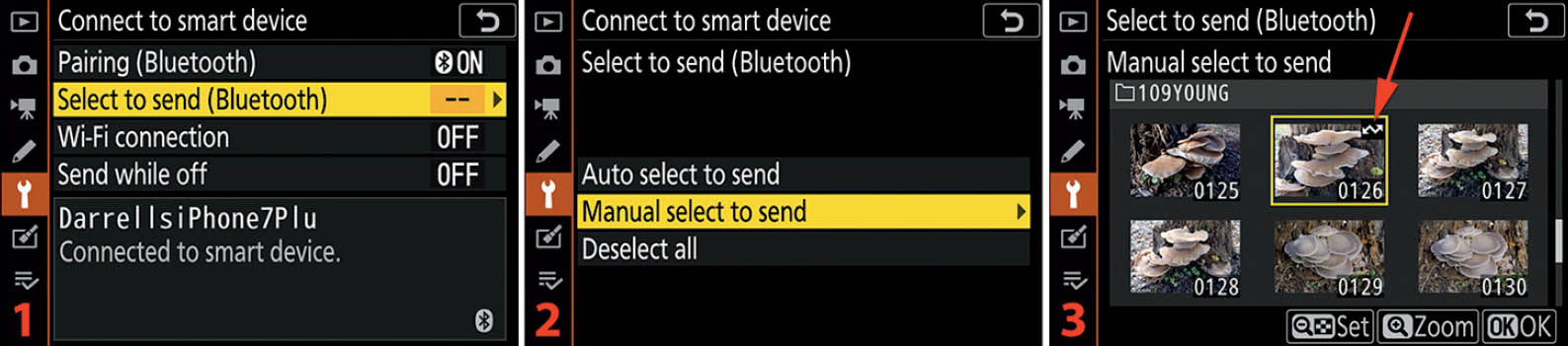
Figure 10.27I: Manual select to send (via Bluetooth)
Use the following steps to manually select images to send from your camera to your smart device:
- 1. Choose Select to send (Bluetooth) from the Setup Menu > Connect to smart device screen and scroll to the right (figure 10.27I, image 1).
- 2. Highlight Manual select to send and scroll to the right (figure 10.27I, image 2).
- 3. You will be presented with a screen of six image thumbnails (figure 10.27I, image 3). You can select or deselect an image by scrolling to it and pressing the Zoom out button, or you can simply tap the thumbnail. When selected, a small send-to-device symbol (like a sideways lightning bolt) will be displayed in the top-right corner of the thumbnail (red arrow). You can zoom in to look at an image full screen by tapping the Zoom symbol or pressing the Zoom in button. Choose as many images as you would like and mark them for transfer. When you are finished, press or touch OK and the camera will briefly pop up a small window that says Selection complete. When the camera next connects to SnapBridge on your smart device, it will automatically transfer any marked images, as long as Auto link > Auto download is enabled under SnapBridge.
Settings Recommendation: I normally use Manual select to send when I want to send images to SnapBridge. I don’t like filling up my smart device’s limited storage with hundreds of images, even if they are only the “2 megapixels” versions that SnapBridge’s Auto link > Auto download offers.
If you need to transfer all the images you take, why not use the Connect to PC function described in the next main chapter section (page 542). You can send your images directly to your laptop computer’s much larger hard drive as you take them. The camera can use an existing local Wi-Fi network that both the camera and computer are members of (access-point Wi-Fi), or a one-to-one (ad hoc Wi-Fi) connection—directly between your Z6 and your computer—without using any outside wireless networks. The Z6 is a flexible little camera!
Deselect All
The Deselect all setting allows you to deselect all images marked for transfer. If you have been out shooting all day and accidentally have Auto select to send (page 535) selected, your camera is just itching to find SnapBridge so that it can send the 675 pictures you just took and fill up your smart device’s storage.
To prevent this large image transfer from taking place, you can use the Deselect all setting to deselect all marked images. Later, you can transfer only the ones you want with Manual select to send (page 535).

Figure 10.27J: Deselect all
Use the following steps to deselect all images and prevent their automatic transfer:
- 1. Choose Select to send (Bluetooth) from the Setup Menu > Connect to smart device screen and scroll to the right (figure 10.27J, image 1).
- 2. Highlight Deselect all and scroll to the right (figure 10.27J, image 2).
- 3. A popup window will appear with the warning question, Deselect all images? Highlight Yes and press or touch OK to remove the send markings from all images, or select No to cancel.
Wi-Fi Connection
Wi-Fi connection is best used when transferring large numbers of images and large items like videos to your smart device. You must make a Wi-Fi connection not entirely unlike when you connect a new smartphone or tablet to your home Wi-Fi.
Basically, the camera wants to be the Wi-Fi access point for your smartphone. While using the Wi-Fi connection, your smart device will not be able to access the internet. Instead the camera and smart device will be connected in a private (ad hoc) Wi-Fi network between the two devices only.
From the camera, it is quite easy to initiate the connection; however, you will need to know how to choose a Wi-Fi network from your smart device’s settings app. Instead of choosing your normal home Wi-Fi network, you must choose the camera’s Wi-Fi connection. Let’s see how to initiate the Wi-Fi connection between the camera and your smart device.
Establish Wi-Fi Connection
There are two steps to establishing a Wi-Fi connection between your camera and a smartphone or tablet:
- 1. Enable Wi-Fi on the camera.
- 2. Connect to the camera’s Wi-Fi connection from your smart device.
We will be considering how to enable Wi-Fi on the camera; however, it is beyond the scope of this book to describe (other than roughly) how to connect a smart device to the camera’s Wi-Fi connection. There are simply too many smart devices out there, with slightly different ways to connect to a Wi-Fi network. Again, connecting to the camera’s Wi-Fi is very similar to what you have surely done in the past when you connected your smart device to your home Wi-Fi. In other words, the Z6 becomes the source for your smart device’s Wi-Fi connection instead of your home Wi-Fi.

Figure 10.27K: Establishing an initial Wi-Fi connection
Use the following steps to enable the Wi-Fi connection in your camera so that you can connect your smart device to the camera’s private Wi-Fi network:
- 1. Choose Wi-Fi connection from the Setup Menu > Connect to smart device screen and scroll to the right (figure 10.27K, image 1).
- 2. Highlight Establish Wi-Fi connection and press the OK button or tap the option with your fingertip (figure 10.27K, image 2).
- 3. The camera will briefly display a screen that tells you: Wi-Fi connection established. While connected to Wi-Fi, images will not be sent automatically (figure 10.27K, image 3), and then the final screen will display. Although this screen makes it seem that the camera is already connected to a smart device, it is not. The camera is merely broadcasting a Wi-Fi signal at this point and is waiting for you to connect your smart device to the camera’s Wi-Fi by entering the SSID and Password provided into your smart device’s Wi-Fi settings app (next step).
- 4. The Wi-Fi connection screen shown in figure 10.27K, image 4, gives you connection information that you can use to connect your smart device to the camera. You have three minutes to do so before the camera times out and shuts down its Wi-Fi. Therefore, using your smart device’s settings app, choose the camera SSID (e.g., Z_7_3001781) and enter the Password (e.g., NIKONZ_7). Once the camera and smart device are connected you can then use the Wi-Fi features of the SnapBridge app to do things like transfer selected images and remotely control the camera.
Smart device connection info: Here is rough information on finding and establishing the Wi-Fi connection on smart devices:
- iOS: To connect to an iPhone or iPad, use the following path to enter a connection name (SSID) and password: Setting app > Wi-Fi > Choose a network. Choose the SSID (e.g., Z_7_3001781) and enter the password (e.g., NIKONZ_7), and when a check mark appears you are connected to the camera.
- Android: Swipe down from the top and look for the Wi-Fi symbol. Tap the symbol and look for the SSID (e.g., Z_7_3001781) and then enter the password (e.g., NIKONZ_7). The smart device will obtain an IP address and then will display “Connected, no internet” under the SSID name. The camera and Android are connected.
- SnapBridge: Try to use any feature in the SnapBridge app (e.g., Download pictures, Remote photography) and SnapBridge will ask you if you want to enable Wi-Fi. You will see this message: Enable camera Wi-Fi, You must switch to Wi-Fi to use this feature. Note: Some time may be required to switch. Cancel/Ok. Choose OK and SnapBridge will ask you: SnapBridge wants to Join Wi-Fi network Z_7_3001781_SnapBridge? Click Join.
Wi-Fi Connection Settings
The camera provides default Wi-Fi connection information, including an SSID of “Z_6_” followed by your camera’s serial number (e.g., Z_6_1234567) and a password of NIKONZ_6. If you would prefer to use a more secure connection, in case an unauthorized person may try to connect to your camera over Wi-Fi, you can use the following steps to create a new SSID and Password, along with other Wi-Fi settings. Let’s examine how to configure a more secure Wi-Fi connection.
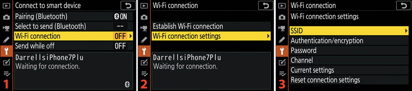
Figure 10.27L: Configuring secure Wi-Fi settings
Use the following steps to create a more secure Wi-Fi environment than the camera’s default settings:
- 1. Choose Wi-Fi connection from the Setup Menu > Connect to smart device screen and scroll to the right (figure 10.27L, image 1).
- 2. Select Wi-Fi connection settings and scroll to the right (figure 10.27L, image 2).
- 3. The Wi-Fi connection settings menu gives you six settings that you can use to make the camera’s Wi-Fi connection more secure (figure 10.27L, image 3). Let’s consider each of these settings individually.

Figure 10.27M: Choosing an new SSID
- 4. Figure 10.27M continues where figure 10.27L ends. Choose SSID from the Wi-Fi connection settings menu and scroll to the right (figure 10.27M, image 1).
- 5. The SSID entry keyboard is shown in figure 10.27M, image 2. You can insert a new SSID by tapping the characters you want to use on the Monitor and they will appear in the position marked with the dark-gray cursor in the SSID field (Z_7_3001781). You can enter up to 36 characters. Use the left/right arrow-tip touch controls in the top-left corner to move left and right in the SSID field. To change from upper to lower case—or to access symbols, such as #—tap the Aa& control in the lower-right corner of the screen (just above the OK touch control). If you make a mistake, position the dark-gray cursor over the error and press or touch Delete. When you’ve finished entering the new SSID, press or touch OK to save it. (Note: If you would prefer not to use the touch-screen features, you can move the selection cursor with the Multi selector pad to highlight a character in the list below the SSID field, then press the OK button to insert the character. To correct an error, turn the rear Main command dial to move back and forth along the field that contains the new SSID, and press the Delete button to remove the error. Press the OK button when you are finished entering the comment.)

Figure 10.27N: Choosing an Authentication/encryption method
- 6. Choose Authentication/encryption from the Wi-Fi connection settings menu and scroll to the right (figure 10.27N, image 1).
- 7. Select OPEN if you do not want any security on your Wi-Fi connection. If you want to encrypt the Wi-Fi signal so that no one but you can access your camera’s Wi-Fi, select the WPA2-PSK-AES setting.

Figure 10.27O: Creating a new Wi-Fi password
- 8. Choose Password from the Wi-Fi connection settings menu and scroll to the right (figure 10.27O, image 1).
- 9. The Password entry keyboard is shown in figure 10.27O, image 2. You can insert a new password by tapping the characters you want to use on the Monitor and they will appear in the position marked with the dark-gray cursor in the password field (NIKONZ_7). You can enter up to 36 characters. Use the left/right arrow-tip touch controls in the top-left corner to move left and right in the Password field. To change from upper to lower case—or to access symbols, such as #—tap the Aa& control in the lower-right corner of the screen (just above the OK touch control). If you make a mistake, position the dark-gray cursor over the error and press or touch Delete. When you’ve finished entering the new password, press or touch OK to save it. (Note: If you would prefer not to use the touch-screen features, you can move the selection cursor with the Multi selector pad to highlight a character in the list below the password field, then press the OK button to insert the character. To correct an error, turn the rear Main command dial to move back and forth along the field that contains the new Password, and press the Delete button to remove the error. Press the OK button when you are finished entering the comment.)

Figure 10.27P: Choosing a new Wi-Fi Channel setting
- 10. Choose Channel from the Wi-Fi connection settings menu and scroll to the right (figure 10.27P, image 1).
- 11. You have two choices: Auto and Manual (figure 10.27P, image 2). Most of us will choose Auto and let the camera figure out which is the best Channel to use. If you decide to use Manual, you will need to scroll to the right and select a Channel.
- 12. When using Manual, you can select Channels from 1 to 8. Press or touch OK to lock in your choice.

Figure 10.27Q: Examining the Current settings
- 13. Choose Current settings from the Wi-Fi connection settings menu and scroll to the right (figure 10.27Q, image 1).
- 14. The Current settings screen is an informational screen showing you a summary of the camera’s current Wi-Fi connection settings so you don’t have to scroll through a bunch of menus (figure 10.27Q, image 2). There are no adjustments to make on this screen.

Figure 10.27R: Resetting the Wi-Fi connections back to factory defaults
- 15. Choose Reset connection settings from the Wi-Fi connection settings menu and scroll to the right (figure 10.27R, image 1).
- 16. A popup screen will display with the warning question: Reset Wi-Fi settings? Yes/No. Choose Yes and press or touch OK to reset the camera’s Wi-Fi settings back to factory defaults, or select No to cancel.
Settings Recommendation: I change the SSID and Password to one I can remember easily, I always use authentication and encryption, and I leave the Channel set to Auto.
Send While Off
The Send while off setting is useful for those times when you have taken a large number of images and want to transfer them to your smart device without standing around waiting for the transfer to continue.
You can enable Send while off, start the transfer process, turn off your camera, and walk away. The camera will not shut down fully until all the images have transferred, and the smart device will usually shut itself off too.

Figure 10.27S: Enabling or disabling Send while off
Use the following steps to enable or disable Send while off:
- 1. Choose Send while off from the Connect to smart device menu and scroll to the right (figure 10.27S, image 1).
- 2. Choose On to enable Send while off, or Off to disable it, and press the OK button or tap the option to lock it in (figure 10.27S, image 2).
Settings Recommendation: I generally don’t use the Send while off feature because I like to monitor any image transfers for problems. Also, I worry about unnecessary battery drain. However, you may want to experiment with this setting to see if it is convenient for you.
Connect to PC
The Connect to PC function allows you to set up a connection for transferring images between your Z6 and a Mac or PC computer. You can connect to the computer on an existing home or business Wi-Fi network (Infrastructure mode), or by directly connecting the camera to a computer, using only the camera and computer’s built-in Wi-Fi (Access-point mode).
Both styles of connection allow you to take a picture and have it transfer immediately to a designated folder on your computer. The camera has built-in Wi-Fi, so it is ready to connect by either style of Wi-Fi connection. Your computer must also have Wi-Fi capability to be used for receiving images (e.g., a laptop, or a desktop unit with a Wi-Fi dongle or card).
The Infrastructure mode is often used when you are at home or in the studio and you want to use your existing Wi-Fi network to connect the camera and computer for image transfer.
The Access-point mode is used when you are out in the field where there are no Wi-Fi networks available. The Z6 becomes a wireless access point and the computer connects to the camera’s Wi-Fi directly.
You will need to download the Nikon Wireless Transmitter Utility for your Mac or PC. You will use the Connect to PC function to connect with the Wireless Transmitter Utility software. Download the software from Nikon at the following web address:
https://downloadcenter.nikonimglib.com/en/download/sw/128.html
If that address doesn’t work, do a Google search for “download Nikon Wireless Transmitter Utility.”
Before you proceed with the camera/computer pairing, be sure to have already installed the Nikon Wireless Transmitter Utility software on your computer so that it’s ready to run.
Now let’s see how to make the two types of Wi-Fi connections between your computer and camera. We will examine each type of connection individually.
Note: In this Connect to PC section, all computer screens are from a Mac computer. All camera screens are from a Nikon Z7. Windows PC and Nikon Z6 screens are the same.
Infrastructure Mode
The Infrastructure mode is just a cool-sounding way of saying that you will connect your camera to your PC or Mac by using an existing wireless home or business network.
You may use this mode to wirelessly transfer images to your PC or Mac across the same in-house wireless network you use to access printers, other computers, and the internet.

Figure 10.28A: Initial Wi-Fi network profile creation
Use the following steps to connect your camera to an existing Wi-Fi network:
- 1. Choose Connect to PC from the Setup Menu and scroll to the right (figure 10.28A, image 1).
- 2. Select Network settings from the Connect to PC menu and scroll to the right (figure 10.28A, image 2).
- 3. Highlight Create profile and scroll to the right (figure 10.28A, image 3).

Figure 10.28B: Searching for an existing Wi-Fi network
- 4. Choose Search for Wi-Fi network from the Connection wizard screen and press or touch OK (Next) to start the search (figure 10.28B, image 1). (Note: If your Wi-Fi network router can use Push-button WPS or Pin-entry WPS, you can tap the Easy Connect control at the bottom of the screen and bypass the rest of these pairing steps. See your Wi-Fi router’s user’s manual for information on how to use the WPS modes.)
- 5. The Connection wizard screen will display Searching while the camera looks for usable Wi-Fi networks (figure 10.28B, image 2). Discovering Wi-Fi sources may take several seconds, so be patient.
- 6. The Connection wizard screen will now display a list of available Wi-Fi network names (SSIDs). This works in a similar manner to how you have connected other devices to Wi-Fi networks in the past. The list will show your local Wi-Fi connection(s) and your neighbors’ Wi-Fi connection(s). If a small lock symbol appears before the SSID name, it means the SSID requires a password to connect. If there is no lock symbol, the Wi-Fi source is “open” and does not require a password, nor is it secure. Choose your known and secure Wi-Fi SSID (mine is COMPULEGAL1) and press or touch OK (Next) to select the Wi-Fi network. Of course, your list of SSIDs will be different from my list of SSIDs.

Figure 10.28C: Entering the password (encryption key) for your Wi-Fi network
- 7. The Connection wizard will now display a blank data input field for entering the password for the selected Wi-Fi network connection (figure 10.28C, image 1). Press or touch OK, or tap the data input field, and a password screen will open.
- 8. You can insert the Wi-Fi password by tapping the characters you want to use on the Monitor and they will appear in the position marked with the dark-gray cursor in the password field (Password). My actual Wi-Fi password is obscured by the red Password shown. You can enter up to 36 characters. Use the left/right arrow-tip touch controls in the top-left corner to move left and right in the Password field. To change from upper to lower case—or to access symbols, such as #—touch the Aa& control in the lower-right corner of the screen (just above the OK touch control). If you make a mistake, position the dark-gray cursor over the error and press or touch Delete. When you’ve finished entering the new password, press or touch OK to save it. (Note: If you would prefer not to use the touch-screen features, you can move the selection cursor with the Multi selector pad to highlight a character in the list below the password field, then press the OK button to insert the character. To correct an error, turn the rear Main command dial to move back and forth along the field that contains the new Password, and press the Delete button to remove the error. Press the OK button when you are finished entering the comment.)

Figure 10.28D: Obtaining an IP address
- 9. The camera must now obtain an IP address (camera identifier) and sub-net Mask (host address range identifier) from the Wi-Fi network by using DHCP (Dynamic Host Configuration Protocol). Don’t worry, you don’t have to do anything except follow these screens; the camera and Wi-Fi network know how to communicate and handshake with each other. (Geek Note: if you are networking savvy and want to manually enter a static IP address and sub-net Mask after manually assigning a static IP and mask to your camera in your Wi-Fi router, the camera will allow you to do that with the Enter manually setting [figure 10.28D, image 2]. Most of us will ignore the Enter manually setting and use the Obtain automatically setting instead.) As seen in figure 10.28D, image 1, the Connection wizard will report Connected to your selected SSID (e.g., COMPULEGAL1). In a moment it will automatically switch to the next screen.
- 10. As shown in figure 10.28D, image 2, the Connection wizard now requests that you choose how the IP address and Mask are obtained. To make things easy for yourself, choose Obtain automatically and press or touch OK.
- 11. The camera will handshake with the Wi-Fi network and automatically obtain an IP address (e.g., 010.001.010.069) and Mask (e.g., 255.255.255.000). When it is done, the camera will display the current connection information. Press or touch OK (Next) to continue. The camera is now connected to the local Wi-Fi network, but is not yet paired with your computer.
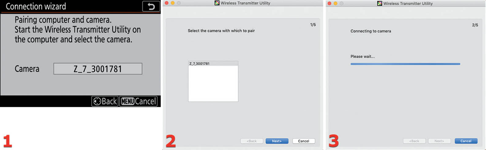
Figure 10.28E: Pairing the computer and camera – Camera selection
- 12. Now it’s time to connect the camera to the computer. It is important that the computer also be connected to the same Wi-Fi network to which the camera is connected. Therefore, if it is not already connected, connect your computer to your Wi-Fi network (beyond the scope of this book). Your camera will be displaying the Connection wizard screen shown in figure 10.28E, image 1. Your camera name will be displayed in the Camera data field (e.g., Z_7_3001781). At this point you must run the Nikon Wireless Transmitter Utility.
- 13. When the Wireless Transmitter Utility first runs, and even before it displays a window on your computer, it seeks a Nikon camera on the local Wi-Fi network. If it finds your camera, the Wireless Transmitter Utility window will open and display a message that reads Select the camera with which to pair, with the name of your camera in a white box (figure 10.28E, image 2). Choose your camera name (e.g., Z_7_3001781) from the box and click the Next> button on the Wireless Transmitter Utility computer screen.
- 14. The Wireless Transmitter Utility will now display a window that says Connecting to camera, while a progress indicator moves across the window.

Figure 10.28F: Pairing the computer and camera – One-time pairing code entry
- 15. Once the Wireless Transmitter Utility locates your camera, the computer will display a window that says Enter the authentication code displayed on the camera monitor, with an Auth. code data entry box (figure 10.28F, image 1). It is awaiting your entry of an Auth. code (authorization code).
- 16. At the same time that your computer is displaying the window seen in figure 10.28F, image 1, the camera will display a Pairing computer and camera screen with an Auth. code (e.g., 8347), as seen in figure 10.28F, image 2.
- 17. Enter the Auth. code from your camera into the Auth. code data entry field on your computer. Click the Next> button (figure 10.28F, image 3).
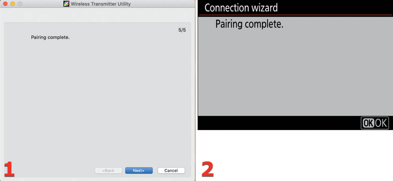
Figure 10.28G: Pairing the computer and camera – Pairing is complete!
- 18. Figure 10.28G, images 1 and 2, show the Pairing complete screens displayed by the computer and camera. Click the Next> button on the computer screen and press or touch OK on the camera to finalize the pairing.
Congratulations! The camera and computer are now connected through your local Wi-Fi network and you are ready to configure the computer to receive images. See the upcoming chapter subsection Choosing a Picture Folder for Image Transfer (page 550). But first, let’s consider how to make a direct connection between your camera and a computer, with no external Wi-Fi network required.
Access-Point Mode
The Access-point mode is an impressive-sounding way of saying that you will connect your camera to your PC or Mac directly, on a wireless, ad hoc network between the camera and computer only. The camera will become a wireless access point with which the computer can connect.
You may use this mode to wirelessly transfer images to your PC or Mac on a private connection controlled by the camera. There is generally no Internet access on your computer while using this mode. You can use Access-point mode even when no Wi-Fi is normally available, such as when out shooting in nature or at a sports event.

Figure 10.28H: Initial Access-point mode connection screens
Use the following steps to make a wireless connection between a single computer and your camera:
- 1. Choose Connect to PC from the Setup Menu and scroll to the right (figure 10.28H, image 1).
- 2. Make sure the Wi-Fi connection is enabled (On), using the Wi-Fi connection setting at the top of the menu in figure 10.28H, image 2. Now select Network settings and scroll to the right (figure 10.28H, image 2).
- 3. You will see a list of network connections if you have previously made any (e.g., COMPULEGAL1). At the bottom of the list is the Create profile setting (figure 10.28H, image 3). Select it and scroll to the right.

Figure 10.28I: Connect a computer directly to your camera
- 4. You now have two choices: Search for Wi-Fi network (see previous Infrastructure Mode subsection on page 543) and Direct connection to PC, which is what we will do in this Access-point mode subsection. Highlight Direct connection to PC and press or touch OK (Next) to proceed.
- 5. When you see the Connection wizard screen shown in figure 10.28I, image 2, the camera has started broadcasting a Wi-Fi signal. Its SSID and Key (password) are shown on the screen. The camera has become a wireless access point to which your computer can connect—using the Wireless Transmitter Utility. Now run the Wireless Transmitter Utility software on your computer so that it can connect to the camera.
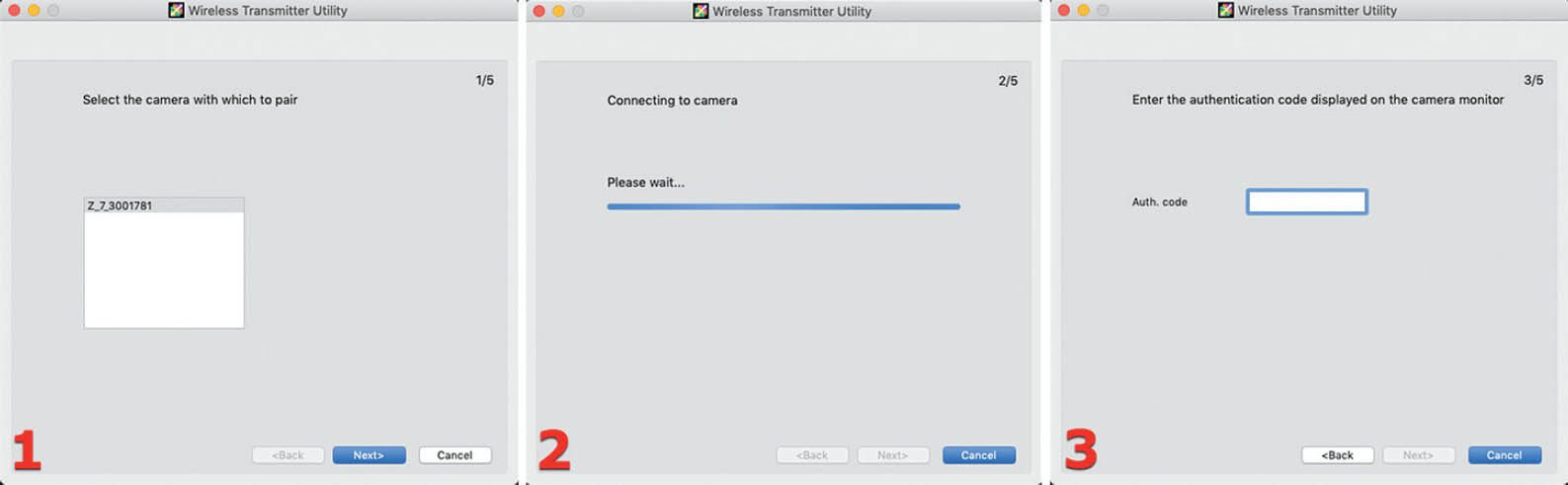
Figure 10.28J: Connecting the Wireless Transmitter Utility to the camera
- 6. A Wireless Transmitter Utility software window will open with a screen that asks you to Select the camera with which to pair (figure 10.28J, image 1). Below the request is a box containing your camera name (e.g., Z_7_3001781). Select your camera name and press the Next> button.
- 7. The computer will now seek a connection with the camera (figure 10.28J, image 2). You will see the window that says Connecting to camera, Please wait . . . along with a progress indicator. Wait for several seconds while the camera and computer communicate.
- 8. After they are done communicating, another window will open on the computer, with the words Enter the authentication code displayed on the camera monitor (figure 10.28J, image 3). An Auth. code data entry field will await the entry of a code provided by the camera.

Figure 10.28K: Entering the authentication code
- 9. The camera will display an Auth. code on its Monitor (figure 10.28K, image 1). Enter the provided authentication code into the blank Auth. code field on the Wireless Transmitter Utility computer screen (e.g., 9531). Press the Next> button on the Wireless Transmitter Utility window.

Figure 10.28L: The camera and computer are wirelessly paired with each other
- 10. A screen that says Pairing complete will be displayed on both the computer and camera (figure. 10.28L, images 1 and 2). The devices are now paired and ready to transfer images.
Congratulations! The camera and computer are now directly connected through an ad hoc Wi-Fi network that works between the camera and computer only. Now you should configure a picture folder to receive images on your computer. Let’s see how to do that.
Choosing a Picture Folder for Image Transfer
Once you have made a connection between your camera and computer, using either Infrastructure mode (page 543) or Access-point mode (page 547), you must set up a folder to receive images. Afterward, you will use the Options menu (next subsection) to select how and when images will be transferred to your picture folder. Let’s see how to create a picture folder on your computer.
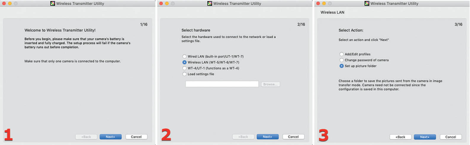
Figure 10.28M: Initial steps in creating a picture folder to receive images wirelessly
Use the following steps to create a picture folder to wirelessly receive images from your camera:
- 1. Run the Wireless Transmitter Utility on your computer. A Welcome to Wireless Transmitter Utility! window will open (figure 10.28M, image 1). It will give you two items of information: [1] Before you begin, please make sure that your camera’s battery is inserted and fully charged. The setup process will fail if the camera’s battery runs out before completion. [2] Make sure that only one camera is connected to the computer. Click the Next> button to continue.
- 2. A Select hardware window will open next (figure 10.28M, image 2). It has the message: Select the hardware used to connect to the network or load a settings file. You have a choice of four items. Click the second item on the list: Wireless LAN (WT-5/WT-6/WT-7), and then click the Next> button.
- 3. A Select Action screen will appear next (figure 10.28M, image 3), with the message: Select an action and click “Next”. There are three selections available and you should choose the last item: Set up picture folder. Click the Next> button to continue.

Figure 10.28N: Final steps in creating a picture folder
- 4. A Select destination folder window will open (figure 10.28N, image 1). It asks you to Choose the place where the images from the camera are stored when operating in image transfer mode. Below the request message is a data entry field with a Browse . . . button. Click the Browse . . . button and choose a folder for receiving images. Once you have chosen your picture folder, click the Next> button to continue.
- 5. The final window will now open with the heading Action completed successfully, and a message stating: The folder will receive images from the camera. There are two selections on this window. Click the first one, Finish wizard, and then press the Next> button to finish.
You have completed the configuration of your computer’s picture folder. Your camera is ready to send images, and the computer is ready to receive images and save them to the picture folder. Now you need to make a choice as to how and when images will transfer to the computer.
Options (for Image Transfer)
The camera gives you four Options for sending images to your computer. Here is a list of the Options and what each does:
- Auto send: Once you have taken a picture and it has been written to the memory card, the camera will send it to your computer. Pictures taken during a video recording, and the video recording itself, are not automatically sent to the computer. You must manually send them afterward.
- Delete after send: Once you have taken a picture and it has been saved to the memory card, it will then transfer to your computer. When the image has successfully transferred to the computer, the camera will delete the image from its memory card. In all cases, sequential image numbering is used, regardless of the settings for Custom setting d7 File number sequence (page 405).
- Send file as: When you are taking pictures in one of the NEF (RAW) + JPEG modes, you can use this setting to select whether to send the JPEG image only or both the NEF (RAW) and JPEG images.
- Deselect all?: Use this setting to unmark all images marked for sending to the computer (or SnapBridge). If the camera is actively sending images, it will stop immediately.
Now let’s see how to select one of these image transfer options.
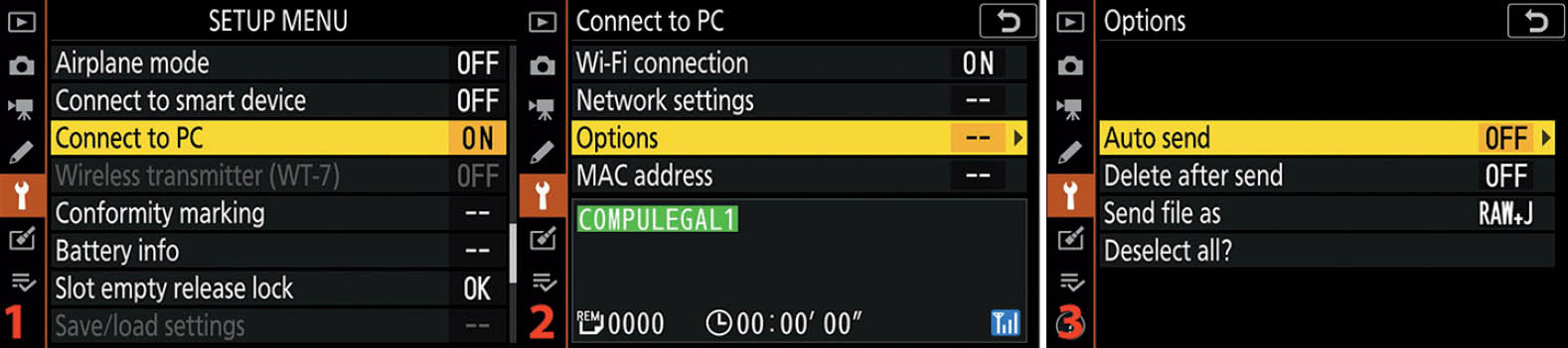
Figure 10.28O: Four image transfer Options
Use the following steps to send copies of your images to your computer:
- 1. Choose Connect to PC from the Setup Menu and scroll to the right (figure 10.28O, image 1).
- 2. Select Options and scroll to the right (figure 10.28O, image 2).
- 3. You are presented with four choices, as described in the previous list (figure 10.28O, image 3). Let’s examine how to choose each option.
Auto Send

Figure 10.28P: Auto send
Use the following steps to Auto send copies of your images to your computer:
- 1. Figure 10.28P begins where figure 10.28O ends. Choose Auto send from the Options menu and scroll to the right (figure 10.28P, image 1).
- 2. Referring to the previous list, choose On to enable or Off to disable Auto send (figure 10.28P, image 2). Press the OK button or tap the option to select it.
Delete After Send

Figure 10.28Q: Delete after send
Use the following steps to delete the images from your camera’s memory card after they are sent to your computer:
- 1. Figure 10.28Q begins where figure 10.28O ends. Choose Delete after send from the Options menu and scroll to the right (figure 10.28Q, image 1).
- 2. Referring to the previous list, choose Yes to enable or No to disable Delete after send (figure 10.28Q, image 2). Press the OK button or tap the option to select it.
Send File As

Figure 10.28R: Send file as
Use the following steps to send JPEG only or NEF (RAW) + JPEG copies of your images to your computer:
- 1. Figure 10.28R begins where figure 10.28O ends. Choose Send file as from the Options menu and scroll to the right (figure 10.28R, image 1).
- 2. Referring to the previous list, choose NEF (RAW) + JPEG to enable RAW and JPEG sending, or JPEG only to only send JPEGs (figure 10.28R, image 2). Press the OK button or tap the option to select it.
Deselect All?
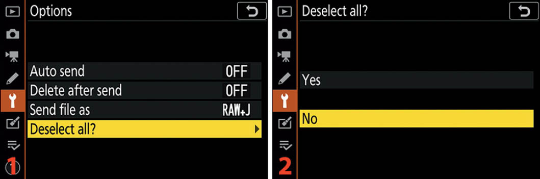
Figure 10.28S: Deselect all
Use the following steps to deselect all images marked for sending to your computer or smart device:
- 1. Figure 10.28S begins where figure 10.28O ends. Choose Deselect all? from the Options menu and scroll to the right (figure 10.28S, image 1).
- 2. Choose Yes to deselect all marked images or No to leave marked images selected for transfer (figure 10.28S, image 2). Press the OK button or tap the option to select it.
Image Sending Screen
In figure 10.28T you can see the screen shown when images are transferring. The file name of the image currently being transferred is shown in dark blue (e.g., _1DY0180.NEF), followed by Now sending.
At the bottom of the sending area, you will see the number of remaining images (e.g., REM 0001), the approximate time remaining (e.g., 00:01’ 20”) and the Wi-Fi signal strength in light blue on the bottom right (mine shows three bars, or full strength).

Figure 10.28T: Image(s) sending from camera to computer
MAC Address
For those who need to use their camera to connect to and use various network resources, it is imperative to have the MAC address of the camera available. Use this function to view the MAC address, which never changes.

Figure 10.28U: Viewing the camera’s MAC address
Use the following steps to view the MAC address of your Z6:
- 1. Choose MAC address from the Connect to PC menu and scroll to the right (figure 10.28U, image 1).
- 2. The MAC address is displayed (figure 10.28U, image 2).
Note: The MAC (Media Access Control) address has nothing to do with an Apple Mac computer. It is a unique series of characters assigned to each device with networking capabilities to help identify the device as a unique entity on a network.
Wireless Transmitter (WT-7)
With a Nikon WT-7 or WT-7a wireless transmitter attached to the Nikon Z6, the camera will be able to link with a computer or an FTP server by using a wireless or Ethernet network. The camera already has this functionality to some degree using less expensive tools and functions, such as SnapBridge (page 528), Connect to PC (page 542), and the WR-R10 wireless transmitter (page 523) along with the camera’s built-in Wi-Fi and Bluetooth. While connected to a WT-7/a you will have the following settings under your control:
- Wireless transmitter
- Choose hardware
- Network settings
- Options
The primary benefit you will receive by using the rather expensive WT-7a transmitter is a more robust radio signal and greater range compared to the other wireless solutions mentioned earlier. It is unlikely that most of us will need the power of this high-end transmitter. If you have that need, you will already know it. If you are not sure, please do some research to see how the WT-7/a might benefit you.
The use of a WT-7/a transmitter is beyond the scope of this book. Please refer to the user’s manual included with your Nikon WT-7 or WT-7a transmitter for details on using it to replace the camera’s built in functionality and less expensive solutions.
Conformity Marking
Conformity marking is a simple function that lets you see the symbols for the various industry standards with which your camera conforms. These standards have symbols that you can research if you so desire.

Figure 10.29: Viewing the symbols for the Nikon Z6’s standards conformity
Use the following steps to view the camera’s conformity standards:
- 1. Choose Conformity marking from the Setup Menu and scroll to the right (figure 10.29, image 1).
- 2. Figure 10.29, image 2, shows the Conformity marking screen with the symbols of conformity. Press or touch OK (Done) when you are finished viewing the symbol(s).
Battery Info
The Battery info screen (figure 10.30, image 2) will let you know how much battery charge has been used (Charge), how many images have been taken with this battery since the last charge (No. of shots), and how much life the battery has before it will no longer hold a good charge (Battery age).
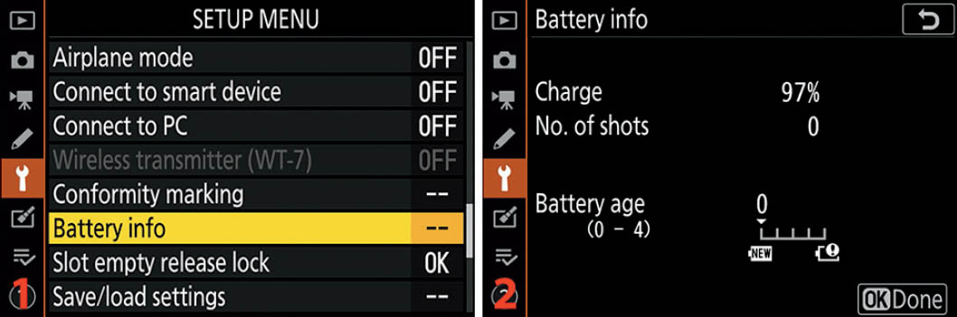
Figure 10.30: Battery info screen
Here are the steps to examine the Battery info:
- 1. Select Battery info from the Setup Menu and scroll to the right (figure 10.30, image 1).
- 2. The next screen is the Battery info screen (figure 10.30, image 2). It is just for information, so there’s nothing to set. When you’ve finished examining your camera’s Battery info, press or touch OK (Done) to exit.
The Z6 goes a step further than most cameras. Not only does it inform you of the amount of charge left in your battery, it also lets you know how much life is left. After some time, all batteries weaken and won’t hold a full charge. The Battery age meter will tell you when the battery needs to be completely replaced. It shows five stages of battery life, from 0 to 4, so you’ll be prepared to replace the battery before it gets too old to take many shots.
Settings Recommendation: It’s important to use Nikon brand batteries in your Z6 so they will work properly with the camera. Aftermarket batteries may not charge correctly in the Z6 battery charger. In addition, they may not report correct Battery age information. There may be an aftermarket brand that works correctly, but I haven’t found it. Instead, I use the batteries designed by Nikon to work with this camera. I am a bit afraid to trust a camera that costs this much to a cheap aftermarket battery of unknown origin.
Slot Empty Release Lock
Slot empty release lock defaults to locking the shutter when you try to take an image without a memory card inserted in the camera. By enabling it, you can take pictures without a memory card but cannot save them later.
This function exists so that when you have your camera tethered to your computer using Nikon Camera Control Pro 2 software (not included), you can send pictures directly to the computer, bypassing the memory card.
You can allow the camera to take pictures with no card inserted when you select the OK Enable release setting. Here is a description of both settings:
- LOCK Release locked: When you choose this setting, your camera will refuse to release the shutter when there is no memory card present.
- OK Enable release: Use this setting if you want to use the optional Camera Control Pro 2 software to send images directly to a computer. If the camera is not tethered to a computer, it uses “Demo mode,” which will display an image on the camera’s Monitor, but you will have no way to save the image.

Figure 10.31: Slot empty release lock
Here are the steps used to configure Slot empty release lock:
- 1. Select Slot empty release lock from the Setup Menu and scroll to the right (figure 10.31, image 1).
- 2. Choose one of the two settings from the list (figure 10.31, image 2). Press the OK button or tap the option to lock in the setting.
Settings Recommendation: I tried using the OK Enable release setting as an experiment. I found that there is no real reason to use this setting other than when the camera is tethered to a computer. You cannot save the images in the memory buffer to a memory card later.
Save/Load Settings
Do you have your Z6 set up exactly the way you like it? Have you spent hours and hours reading this book and the Z7/Z6 User’s Manual, or simply exploring menus, and finally you finally have all the settings in place? Are you worried that you might accidentally reset your camera or that it could lose its settings in one way or another? Well, worry no more! Save/load settings writes configuration settings to the memory card, allowing you to back up camera settings to your computer.
When you have your camera configured to your liking, or at any time during the process, simply use the Save/load settings function to save the camera configuration to your memory card. It creates a small file whose name begins with NCSET followed by three numbers that vary by camera (e.g., 001), and ending in .BIN, into the root directory of your Z6’s memory card (e.g., NCSET001.BIN). You can then save that file to your computer’s hard drive and have a backup of your camera settings.

Figure 10.32: Save/load settings
Here are the steps to save or load the camera’s settings:
- 1. Choose Save/load settings from the Setup Menu and scroll to the right (figure 10.32, image 1).
- 2. Select Save settings or Load settings from the Save/load settings menu, and then follow one of these two easy procedures (figure 10.32, images 2):
- Save settings: Select Save settings and press the OK button or tap Save settings with your fingertip (figure 10.32, image 2). Your most important camera settings will be saved to the root directory of your memory card. Afterward, copy the .BIN settings file (e.g., NCSET001.BIN) to your computer for safekeeping. Warning: You may notice that on the Save/load settings screen the Load settings selection is grayed out on your camera. If Load settings is not grayed out when you get ready to save the settings, be careful—you are about to overwrite previously saved settings that are currently on the memory card. The only time you’ll see Load settings not grayed out is when a .BIN file already exists on the memory card.
- Load settings: Insert a memory card with a previously saved .BIN file (e.g., NCSET001. BIN) in the card’s root directory, select Load settings, and press the OK button or tap Load settings with your fingertip (figure 10.32, image 2). The settings you previously saved will be reloaded into the Z6 and will overwrite your current settings without prompting you for permission, so be sure that you are ready to have the settings overwritten. If you change the name of the .BIN file, the Z6 will not be able to reload your settings.
Here is a list of settings that are saved or loaded when you make use of one of these functions. It doesn’t save or load every setting in the Z6, only the ones listed here:
Playback Menu (5 settings)
- Playback display options
- Image review
- After delete
- After burst, show
- Rotate tall
Photo Shooting Menu (all four banks included, 25 settings)
- File naming
- Choose image area
- Image quality
- Image size
- NEF (RAW) recording
- ISO sensitivity settings
- White balance (includes fine-tuning adjustments and presets d–1 to d–6)
- Set Picture Control (Custom Picture Controls are saved as Auto)
- Color space
- Active D-Lighting
- Long exposure NR
- High ISO NR
- Vignette control
- Diffraction compensation
- Auto distortion control
- Flicker reduction shooting
- Metering
- Flash control
- Flash mode
- Flash compensation
- Focus mode
- AF-area mode
- Vibration reduction (settings may vary by lens mounted)
- Auto bracketing
- Silent photography
Movie Shooting Menu (25 settings)
- File naming
- Choose Image area
- Frame size/frame rate
- Movie quality
- Movie file type
- ISO sensitivity settings
- White balance
- Set Picture Control (Custom Picture Controls are saved as Auto)
- Active D-Lighting
- High ISO NR
- Vignette control
- Diffraction compensation
- Auto distortion control
- Flicker reduction
- Metering
- Focus mode
- AF-area mode
- Vibration reduction (settings vary by lens mounted)
- Electronic VR
- Microphone sensitivity
- Attenuator
- Frequency response
- Wind noise reduction
- Headphone volume
- Timecode (except for Timecode origin)
Custom Settings (50 settings)
- All Custom Settings except Custom setting d3: Sync. release mode options
Setup Menu (15 settings)
- Language
- Time zone and date (except for Date and time)
- Limit monitor mode selection
- Information display
- Non-CPU lens data
- Clean image sensor
- Image comment
- Copyright information
- Beep options
- Touch controls
- HDMI
- Location data (except for Position)
- Wireless remote (WR) options
- Assign remote (WR) Fn button
- Slot empty release lock
Settings Recommendation: This function is a great idea. After using my camera for a few days and getting it set up just right, I save the settings file to my computer for safekeeping. Later, if I change things extensively for some reason and then want to reload my original settings, I just put the backed-up settings file on a memory card, pop it into the camera, select Load settings, and I’m back in business.
Reset All Settings
The Reset all settings function allows you to do exactly what it says: reset all the settings within the Nikon Z6. At some point in the future, you may want to sell your camera to offset the cost of a new Nikon purchase, or you may just want to start over with fresh settings. This function allows you to do so.
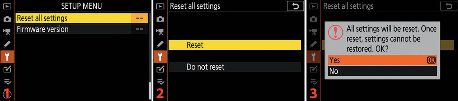
Figure 10.33: Reset all settings in the Nikon Z6
Use the following steps to reset your Z6’s menu settings for a fresh start with menu configuration:
- 1. Select Reset all settings from the Setup Menu and scroll to the right (figure 10.33, image 1).
- 2. If you want to reset the camera’s settings, highlight Reset and scroll to the right (figure 10.33, image 2). Choose Do not reset to cancel.
- 3. Choose Yes from the popup box that asks All settings will be reset. Once reset, settings cannot be restored. OK? (figure 10.33, image 3). Press or touch OK and the camera will execute a settings reset. Choose No to cancel.
Firmware Version
Firmware version is a simple informational screen, like the Battery info screen. It shows you which version of the camera’s operating system (firmware) the Z6 is running. My camera is currently running version C2.00 and LF 1.00 (figure 10.34, image 2).
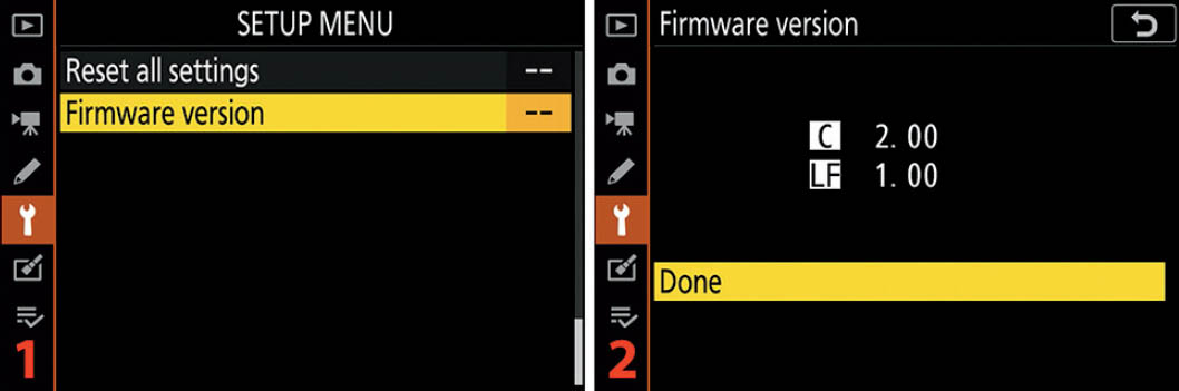
Figure 10.34: Viewing the camera’s Firmware version
Here are the steps to see the Firmware version of your camera:
- 1. Choose Firmware version from the Setup Menu and scroll to the right (figure 10.34, image 1).
- 2. Examine the Firmware version (figure 10.34, image 2). Select Done and press the OK button.
When it’s time to do a firmware update, you will use this same Firmware version menu to update the camera. An extra “Update” menu item will appear below the Done selection (not shown), allowing you to update the firmware. Follow the instructions provided on Nikon’s website for each firmware update.
Author’s Conclusion
Whew! The Z6 may seem like a complicated little beast, but that’s what you get when you fold pro-level functionality into a relatively small DSLM body. For as complex as it is, I’m certainly delighted with it.
Next, we’ll consider how to use the camera’s Retouch Menu to adjust images without using a computer. If you are in the field shooting RAW files and you need a quick JPEG, black-and-white version of a file, or red-eye reduction, the Retouch Menu has you covered.
You can even do things like image distortion and perspective control, color balance changes, filtration, cropping, and image resizing—all without touching a computer. Let’s see how!