4
Subroutine
After studying the principles of basic microprocessor operation and programming in previous chapters, we present here the concept of the subroutine. Thanks to the subroutine, it is possible to implement the concepts of function and procedure of High-Level (programming) Language (HLL) such as C or PASCAL. To be able to do this, a memory called a stack is required. Its operation, as well as that of its subroutine, are studied. This concept has been derived from that of interruption, invented to accelerate I/O (for Input/Output) handling and presented in the chapter that follows for teaching purposes.
NB. The context of this study is a mono-processor unless otherwise indicated.
4.1. Stack memory
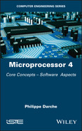
Stack memory simply means the stack as well as the LIFO (Last-In/First-Out) buffer to indicate the order of data circulation. Figure 4.1 shows the graph symbol of a stack S of a size s words.
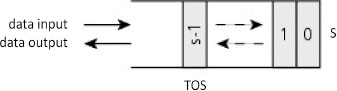
Figure 4.1. Suggested visual representation of a stack S
The word “stack” is an analogy with a stack of plates where the last plate stacked is later the first to be picked up. In our context, the information represents the stack. The location that will be accessed is the top of the stack or TOS (Top-Of-Stack). For information, the data that precedes it takes the name NOS for Next-On-Stack. Two primitives are needed to manage the stack: stack() and destack(). The place occupied by this memory is zero or one word at initialization. The location is a writing action on the stack, and the stack therefore increases in size. Unstacking is a reading action on the stack, and the stack therefore reduces in size. Reading is destructive in the sense that access to the data occurs only once but the information will persist in memory at least until the next stacking action and if there have not been any other unstacking actions between the two operations. These two primitives classically translate for many microprocessors (MPU for MicroProcessor Unit) through instructions respectively push and pop (or pul – pull data from stack from MC6800, for example), hence its other names push-in/pop-out or push-down/pop-up memory. But other MPUs such as the Arm® family offer two generalist transfer instructions ldm and stm (load and store multiple registers). The processor, to manage this memory, should have two to three pieces of data, which are the stack start address, the address of the location stored in the stack pointer and, eventually, the maximum size for detecting a possible overflow. A memory area of maximum size can be reserved for it such as a segment (a concept explained in the next volume). The stack pointer is implemented in the form of a specialized register called, for example, SP (Stack Pointer) in the x86 family. Other registers can be used as a stack pointer. We list, for example, the a7 (address register) from MC68000, r13 for the Arm® family and GPR1 (General-Purpose Register) in PowerPC (Performance Optimization With Enhanced RISC Performance Computing) architecture with an adapted addressing mode such as auto-increment and auto-decrement (cf. § 1.2.3). For Arm®, there are two synonyms, push and pop respectively for instructions ldm and stm that specialize the transfer using the r13 register as a base register and by automatically managing its following access. The benefit of using a general-purpose register1 makes it possible to access the stack at random with, for example, an indexed addressing mode (cf. § 1.2.3.4), which is useful for working with local variables or the parameters of a function/procedure. The registers to be stacked or unstacked can be specified as an operand or are implicit, one example being the instructions pusha (push all) and popa (pop all) from IA-32 (IA for Intel Architecture) that manipulate all the General-Purpose Registers (GPR). Instruction coding usually takes up one byte as there is no specified address in the operand field since it is implicit.
At an implementation in main memory and by representing this with addresses ascending upwards as in the case of Figure 4.5, there are two possibilities: either the stack ascends towards the upper addresses or its ascent moves towards lower addresses (which creates an image of the stack of plates being glued to the ceiling!), hence the final name of push-down or push-down storage (JEDEC 2002, 2013). In the first case, it is called an ascending stack, in the second, a descending stack. In this last case, which is the most classical, a stacking action is linked to a decrement and respectively an unstacking action is linked to an increment of the stack pointer. Depending on the implementations, the action of stacking or unstacking can be made before or after the increment/decrement of the stack pointer. When the stack pointer points the last element stacked or the one that will be the first to be unstacked, the stack is called full. In the case where it points the next free location for a stack, it is called empty. There are therefore four possible solutions for implementation, as listed in Table 4.1. It should be noted that Arm® architecture offers these four possibilities.
Table 4.1. Solutions for managing a stack in main memory
| Stack names | Push | Pop | Examples of implementation |
| FD for Full Descending | Pre-decrement | Post-increment | MC6809, x86, Arm® |
| ED for Empty Descending | Post-decrement | Pre-increment | MC6800, Arm® |
| FA for Full Ascending | Pre-increment | Post-decrement | Arm® |
| EA for Empty Ascending | Post-increment | Pre-decrement | Arm® |
Figure 4.2 shows the pseudo-code of the two main stack manipulation instructions for the x86 family. The stack pointer here points the last stacked element or the next to be unstacked and the pile ascends downward from the memory (full descending stack). The descent value here is 2 as the memory is managed in byte format while the stack is managed in 16-bit word format (= 2 bytes) for reasons of alignment (cf. § 2.6.1 from Darche (2012)) in relation to the processing format for integers of this MPU. It should be noted that, in rare cases, a processor cannot offer this implicit management of the stack pointer. In contrast, one benefit of an explicit management of the stack is choosing its ascent at the price of software cost.
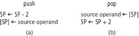
Figure 4.2. Pseudo-code for stacking (a) and unstacking (b) in the format n = 16 bits for the x86 family (Intel)
The TMS320C31 runs the stack system in an upward direction! This means that a push instruction carries out a pre-increment and, pop, a post-decrement of the stack pointer SP. We can also deduce from this that the SP points the last element stacked. In contrast, the other stacks can be managed in two directions. Figure 4.3 summarizes these operations in a writing inspired by C language.
Figure 4.3. Operations of stacking and unstacking for TMS320C31
During operation, two errors can happen, stack overflow2 and stack underflow. Over- and under-flow are caused respectively by excess stacking or unstacking. We consider the pushup stack from Figure 4.4. To detect them, one possibility is to add a stack boundary limit register. Registers B and L make it possible to define the stack boundaries (shaded in the figure). Linked to the SP, they make it possible to detect the errors in its management. The conditions are the following:
if SP > L then (over-)flow;
if SP < B then under-flow.
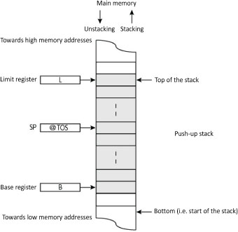
Figure 4.4. Managing an ascending stack
The role of the stack is to store information temporarily. In addition to the return address, the stack may contain other information on the subroutine, hence the name of the execution or run-time stack. It classically contains the ingoing and outgoing parameters also called input and output parameters respectively, as well as local variables belonging to each function being executed (cf. § 4.2.3), as Figure 4.5 illustrates (no nested calls in the example). During execution, a (sub)routine can use the stack to save temporarily the content of a register. To make (cf. § 3.1.4) a subroutine re-entrant or for it to be callable recursively, an area for its local variables is allocated to it on the stack each time it is called. This area is called the stack frame, also called the call frame, activation record or activation frame. The stack frame is dependent on the computer and the ABI (Application Binary Interface, cf. § V5- 1.1.4). To manage it, it is necessary to have a pointer on this area, local to the subroutine, here the indirection register BP (Frame Base Pointer, cf. § 1.2.3.4) from the 8086 microprocessor. It may be necessary to have other pointers of the same type towards frames of higher lexical position in the case of nested calls. This organization is explained in the following section.
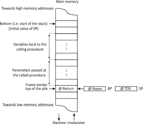
Figure 4.5. Classical structure of an execution stack (x86 family from Intel)
It may seem strange from the perspective of implementation to have an operation of the stack “in reverse”, since the bottom of the stack is situated at the top of the main memory and data stacking increases the stack from the top. But from the perspective of managing the memory, there is none since the programs are stored at the bottom and the stack at the top for optimal management of space, as Figure 4.6 illustrates. Its maximum size is set in programming in assembly language (i.e. declaration of a stack segment3 in x86 architecture, for example) or automatically by the compiler. For information and without going into detail, the other specialized areas that appear in the figure are intended as dynamic and static allocations for, for example, variables such as the BSS (Block Started by Symbol) area or for the instructions.
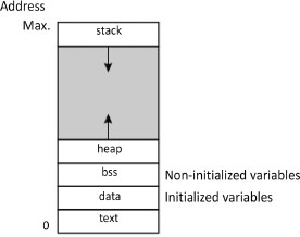
Figure 4.6. Classic main memory mapping
A stack can be managed with software or hardware. With software management, a Random Access Memory (RAM) area, for example, the main memory, is transformed for each program into LIFO. Because it requires using a management program, this solution is necessarily slower than in hardware management of microprocessors. Implantation in a memory stack makes it possible to have a large space, but the problem of protecting access in a multi-task environment is posed. With segmented main memory, a segment is naturally given to it, which moreover limits its maximum size to the size of the segment. The stack can also be implemented in the form of a finite stack register inside the MPU (integrated stack). We speak of a hardware stack, also called a stack cache or stack register file. Each stack shifts the values in the registers, the last element being lost. During unstacking, either the last element is doubled or the null value is injected. In the second case, the accumulator communicates with the top of the stack. At each stacking, the data registered is shifted downward, hence the two other names “cascade stack” or “push-down stack”. This form is faster since it is integrated into the MPU and does not require a stack pointer. In contrast, its number of registers is limited and it shows the drawback of losing data when the structure is full. The reading is then called destructive, unlike the same operation on a memory stack where the data can remain, at least (i.e. if there are no other unstacking operations) until the next stacking. One example is that of the 8087 coprocessor (cf. § V3-5.4) for floating-point calculation, which integrates a stack in the form of 8 registers ST[7:0] in the format n = 80 bits, these also playing the role of a flat register file. In contrast, this component manages its registers in two ways (Figure 4.7). Access can be made as for a stack or by random addressing with classic load (ld) and unload (st) instructions. This mixed management provides suppleness of use.
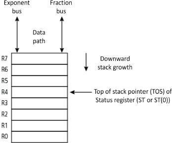
Figure 4.7. Stack register of a mathematical coprocessor in floating point from 8087 (Intel)
A bank of registers can be run as a stack. O’Connor and Tremblay (1997) describe such a structure from the front of a processing unit in the context of a hardware implementation of a virtual Java machine. This stack register file or stack cache is run as a circular memory buffer.
A variant of implementation is a stack whose upper part is located in the processor and the rest in main memory to obtain faster access as with the B5000 mainframe from Burroughs. A final variant, which is not very fast, is implementation with the help of Shift Registers (SR), as illustrated on Figure 4.8. Each bit of the word is managed by an SR. A combinatorial circuit, aided by a modulo maximum size counter, manages positive and negative overflows. It should be noted that elements of the hardware stack shift and the top of the stack is fixed. However, in a software stack, the opposite happens, that is, the elements are static, and the stack pointer is dynamic.
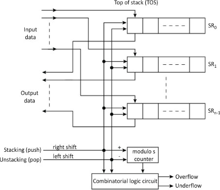
Figure 4.8. Stack in shift-register version
Address alignment (cf. § 2.6.1 in Darche (2012)) at the stack may be necessary for higher-generation 8-bit microprocessors when the memory is run in byte format. This is the case with the Intel x86 family whose transfers are made only in 16- or 32-bit format depending on the component’s working format. Moreover, there is no dynamic control of this alignment, but the assembler controls the operand format during stacking or unstacking. The introduction of a misalignment would introduce serious dysfunction in the system. For ascending compatibility (cf. § 3.3.3) in a family of microprocessors, there may be an address-size attribute that specifies the transfer format of 16, 32 or 64 bits.
4.2. Subroutine
This concept came from the EDSAC (Electronic Delay Storage Automatic Calculator) project under the term “closed subroutine” (Wilkes et al. 1951). A subroutine is a block of instructions that is executed following a call from a calling subroutine. This block is a factorization of a fragment of code that can be used in different places in the application. The call is made by a specialized instruction such as call (x86), bsr (branch to subroutine) or jsr (jump to subroutine). In the same way, the return is made using a specialized instruction such as ret (return, x86) or rts (return from subroutine). This code is duplicated no more than necessary, that is, it is present only once. Instead, it is the number of jumps that is multiplied. The subroutine should not be confused with the macro-instruction (cf. § V5-1.3.4), possibly parametered, each of the expansions adding the corresponding code. Figure 4.9 shows a processor’s single-task activity. Following a call and until a return, the execution flow is passed to the subroutine instructions.
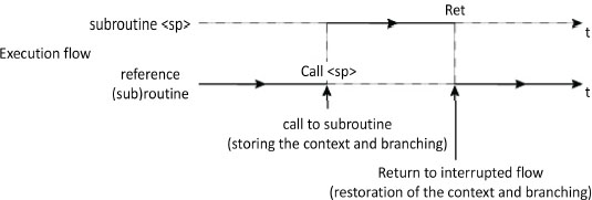
Figure 4.9. Unfolding execution of a program with a call to sub-program
Debranching can take place simply by initializing the Program Counter (PC) with the subroutine start address. To return to the calling program, it is necessary to have the return address. Its value is in fact the instruction address following the one corresponding to the call, that is, the value of the PC after decoding the call instruction but before its effective execution (cf. execution cycle, § V1-3.2.2.4 and V1-3.3.2). It should be saved by the call instruction before initialization of the PC with the branching address and restored on return by the return instruction. There are several methods or places for saving this return address. The most current is the one that uses the stack (Figure 4.10). The stack pointer is run automatically by the call and return instructions, which involves a complex execution. Moreover, once the stack is implanted in main memory (cf. § 4.1), the overhead is higher. The major benefit is proper management of recursivity.
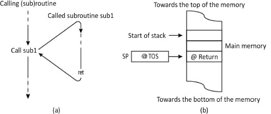
Figure 4.10. Subroutine call and return and stack content (x86 architecture)
The second method is to use a specialized, and thus an implicit register. This latter is called an LR (Link Register), for example, in Arm® and PowerPC architectures, from the name of the operation and to make the execution address correspond with the return address linking method. RISC (Reduced Instruction Set Computer) MIPS (Microprocessor without Interlocked Pipeline Stages) architecture uses the ra (return address) register, also called r31, with the subroutine call instruction jal (jump and link). This solution is simple and fast as it does not involve using the stack. It is useful when a subroutine does not call to another, which is called a leaf (sub)routine. This configuration is generally detected by the compilers. If the context is more complex (saving other registers with the PC or Program Counter), then the additional handling uses software. Moreover, in case of interruption, this can be problematic. The last solution is to use an explicit register for saving. Still using MIPS architecture, the instruction jalr (jump and link register) saves the return address in any register specified in the operand field.
To facilitate implementation of the compilers, high-level instructions can be proposed, such as enter and leave from Intel. Motorola used the equivalent instructions link and unlk for its MC68000. Moreover, it offers up to 10 stack frame formats.
One subroutine call that is not classical is the CDP1802 (also called COSMAC for Complementary Symmetry Monolithic Array Computer). It has its register bank of 16 registers in 16-bit format, each of which could be a PC (Program Counter). Register switching has made it possible to carry out branching to a block of instructions such as a subroutine.
4.2.1. Nested calls
The mechanism is cascadable and potentially recursive, as Figure 4.11 illustrates.
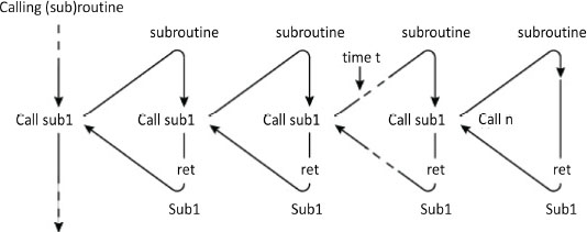
Figure 4.11. Recursive calls and returns from a subroutine (nested calls)
At each call, the return address is saved on the stack. Figure 4.12 shows the state of the stack at instant t. Unstacking, thanks to the LIFO access policy, is carried out in the reverse direction to that of stacking. The call depth will be the number of nested calls carried out. Knowing its maximum value makes it possible to dimension the stack size. If the stack is poorly dimensioned, then there will be a stack overflow. The condition for the recursivity to be passed correctly is that the subroutine’s code should be re-entrant (cf. § 3.1.4). This means that it should not use global or static variables, like a high-level programming language, such as C.
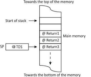
Figure 4.12. Recursive calls and returns from a subroutine (nested calls)
4.2.2. Execution context
It is necessary to save on the stack a set of data needed to make the debranching transparent, that is, to make it as if there had not been any break in the sequence with which the caller is executed. To do this, this set, which is called the execution context, will be restored on the return. It contains at least the return address contained initially in the microprocessor’s program counter to make this debranching transparent. Also, a call instruction from a subroutine can be seen as a macro-instruction (Blaauw and Brooks 1997) as it behaves like a normal instruction by making transparent the execution of the block of instructions representing the subroutine. At most, this involves all the MPU’s registers. Work is distributed between the caller and the called. The backup location is either internal within the registers or external in main memory in a stack.
There are three approaches for carrying out this processor state backup/restoration4. One is for this operation to be implicitly carried out by an instruction. The call instruction and the return instruction save/restore the internal state. One example is the complex instruction calls from the mini-computer’s processor VAX (Virtual Addressed eXtended), which made it possible to choose the registers to be saved. In another approach involving software, instructions are explicitly responsible for carrying out the work. Only the return address is saved automatically. The remainder of the context is the responsibility of the caller or the called depending on the call convention (see the following section). The final approach is an implicit hardware management, one example being register windowing (cf. § V3-3.1.11.3) from the RISC SPARC family (Scalable Processor ARChitecture).
4.2.3. Passing parameters and call conventions
To implement a function or procedure, it is necessary to pass parameters and define who or what will manage them, the caller or the called. We recall that there are ingoing and outgoing parameters, since the function can only have an outgoing parameter, unlike the procedure in PASCAL language, for example. The type of passing defines whether the parameter is passed by the value or by the address, by pointer or by reference5. The mode of passing defines the storage location of the parameter: register, global variable or stack. The MPU 2650 from Signetics has an interesting characteristic: it has two banks of three registers selectable by the RS (Register Select) bit from the state register. These make it possible to pass arguments easily from one process to another by switching the banks, since the accumulator is common to both. The passing can be done explicitly using classical data movement instructions (cf. § 2.2.1) or automatically while executing the call instruction. One example is the MC68020, which, as well as the classic call instruction to a subroutine, has two specialized instructions for modular programming called callm and rtm.
RISC microprocessors have optimized the passing of registers using a mechanism called register file windowing. The hardware implicitly manages the passing of parameters. To do this, a Register File (RF, cf. § V3-3.1.11.1) is subdivided into sub-sections called windows. A window is formed of three parts, which are the block communicating with the lower level, the block for local variables and the block communicating with the higher level. One example is register windowing from the RISC SPARC family (Figure 4.13 (a)). This solution was espoused for calls of low depth (i.e. < 4). The windows overlap at the communication blocks (overlap registers or overlapping register-window). The passage of outgoing and ingoing parameters between the caller and the called occurs between the intermediary of the same registers, which coincide in the windows. In particular, the return address is found in the outgoing parameter area. Only a single window is active at any one time. By using only registers, this approach makes it possible to avoid CPU (Central Processing Unit) time consuming access to the main memory. Moreover, there is a non-windowed area reserved for general-purpose registers. Figure 4.13 (b) shows a linear view of these same registers. This mechanism will be detailed in a future book by the author on the RISC philosophy.
This set of rules defining, among other aspects, what is responsible for backup in the execution context (apart from the PC or Program Counter), is called the calling convention. It is possible to have two backup conventions, caller saving and callee saving. Manufacturers provide a reference document. From Arm®, for example, we list in any order AAPCS (Procedure Call Standard for the Arm® Architecture), APCS (Arm® Procedure Call Standard), TPCS (Thumb® Procedure Call Standard) and ATPCS (Arm® TPCS).
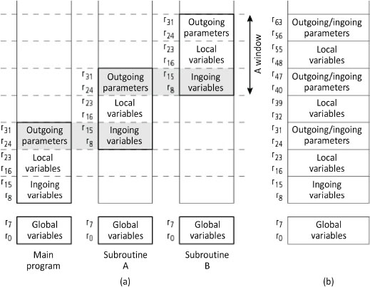
Figure 4.13. Windowing registers (from Scott (2016))
To summarize, we need to distinguish three types of call. The first is the subroutine call where there is, as a minimum, only storage of the return address (in fact, the address present in the PC or Program Counter before the jump) to win time when changing the context. Other registers, depending on the instructions, can be backed up. The second is the function call where two other things must be saved: the parameters to be passed and the local variables. The last is the system call, which occurs without interruption, and is the subject of the following chapter (cf. § 5.4 and 5.8).
4.3. Conclusion
After introducing how the stack and LIFO memory access operates, we studied the concept of the subroutine. This makes it possible to implement a higher-level language function or procedure. A similar mechanism is interruption, which is, like the first mechanism, a re-routing of the execution flow, but one particular direct towards I/O handling. It is studied in the following chapter.
- 1 Historic note: the PDP-11 mini-computer used a general-purpose register, R6, as a stack pointer. The stack was managed with auto-decrement addressing modes with R6 for a stacking and auto-increment, still with R6 for an unstacking.
- 2 To be coherent with floating-point representation, it would have been good to choose the terms “positive and negative overflows”.
- 3 Concept linked to the concept of Virtual Memory (VM), both detailed in a future book by the author on memories.
- 4 Several types of state can be distinguished in an IT system. The state of the processor or internal state refers to the content of registers that are or are not accessible (i.e. “architecture”, cf. § V3-3.1). The external state is that of the system without the processor. It covers the state of the memory hierarchy (for the concept, cf. § V1-2.3 and § 1.2 in Darche (2012)) with, in particular, the caches and main and secondary memories. The state of a process refers to all the information affecting it. It can cover the states of the processor and the operating system if it is in the processing of being executed.
- 5 There is a fourth form of passing called “pass by name” where the name of the argument is passed during the call as in ALGOL 60 (ALGOrithmic Language). This is an address on the variable that is accessed via indirection. This type of passing was used in prefix machines (cf. Meinadier (1971, 1988) on this subject).