5
Interrupt Mechanism
Execution flow (cf. § V1-3.1.2) can also be altered by an interrupt mechanism. We will first introduce the basic mechanism used in the first microprocessors (generations with 4 and 8 bits, cf. Chapter V3-1). Then, we will enrich our model with the concept of exception, present in second-generation microprocessors. This chapter enriches the section dedicated to this in Chapter 4 in Darche (2003) and § 3.2.2. It will be complemented in other books; processor architecture is becoming increasingly complex. The study will be made using different associated aspects such as nested requests, priority requests and vectorization to finish with execution modes and advanced architectures.
5.1. Origin, definition and classification
The concept of software interrupt was implemented for the first time1 in the UNIVAC (Universal Automatic Computer) 1103A (Rojas and Hashagen 2000) at the start of the 1950s (1953 according to Mersel (1956)) to prevent potential overflow (cf. § II-3.1.1. and II-3.3.3. in Darche (2000)) during an arithmetical calculation (Hennessy and Patterson 1994). It was then used for the first time in I/O (Input/Output) in the DYSEAC (Second Standards Electronic Automatic Computer) (Leiner 54) from NBS (National Bureau of Standards) (Smotherman 1989a b). With the development of 16-bit generation microprocessors and the start of the use of Operating Systems (OS) in microcomputers, the concept of interrupt2 encapsulated that of exception (Schlansker and Rau 2000). The interrupt sometimes takes the name of the sub-set that generated the interrupt request, for example, “I/O interrupt” or it bears the name of the cause such as “page fault”.
The general term “interrupt” or IT refers to a class of low-level hardware or software events that forces MicroProcessor Units (MPUs) to interrupt a (sub-)program's normal execution flow, as a jump instruction would do (cf. § 2.4), to re-route to a routine called an interrupt handler (or Interrupt Service Routine, giving the acronym ISR). For its protagonists, whatever generates the request (an I/O controller, an instruction, etc.) is called the “the signaler” and the processing routine is called “the processor”. The processor is responsible for processing the event, ideally in a privileged mode in the case of a processor with several execution levels (cf. § 3.2.2) to then return to a normal execution of the interrupted program or to restart another if it is abandoned. The processing routine should be as fast as possible so as not to slow the main processing or not to lose requests. As Figure 5.1 illustrates, interrupts can be classified by their cause, external or internal to the MPU or linked to management of the memory. What distinguishes the two branches is their (a)synchronous character. The external cause, and so the hardware origin, is always the state of an electrical signal or its variation. It is necessary to distinguish the hardware interrupt and the hardware exception triggered by a malfunction. The internal cause is always linked to the execution of an instruction. For interrupts with an internal cause, the request is always synchronous with the clock since it is linked to the instruction's execution cycle, which generates the request explicitly, and so where it is wanted (software interrupt) or implicitly software exception. But beware, they generally appear at random. The exception is an interrupt category. In this volume3, it is an unprogrammed event, one that is abnormal, unusual and rare4, linked perhaps to a breakdown or an execution error5 which will alter the sequential execution flow. But beware, an error is an exception, but the reverse is not always true. Exceptions the processor is able to detect are of two types, which are faults and aborts. A special operating mode is the step-by-step mode (cf. § 5.5 and 5.6). Inspired by the classification from Intel for its IA-64 (IA for Intel Architecture) and OSs, it is necessary to distinguish four classes of interrupt6, which are distributed in the proposed hierarchy. These are hardware and software interrupts (or trap) and the exception that can be broken down in cases of faults and aborts in both the previous classes.
Criteria other than the origin of the cause can be used to classify interrupts. (Hennessy and Patterson 1990; Walker 1992) and thus suggest criteria that are asynchronous/synchronous, voluntary/forced, masked/unmasked, between or internal to the instruction, precise/imprecise or simple/multi-level, which Tables 5.12 (a) and (b) show at the end of the chapter (cf. § 5.11) after they have been explained.

Figure 5.1. Origins of an interrupt request (Darche 2003)
5.2. External causes
The external interrupt originates in hardware and is asynchronous in nature. It is therefore an unprogrammed event, that is, one not triggered by an instruction (i.e. an unscheduled event). It is therefore more difficult to handle than internal requests, and this is even more true in a multiprocessor environment. Interrupt requests mainly provide I/O controllers, which thus signal a request or indicate an end to the I/O. This is a predicted event. A hardware exception is caused by a hardware malfunction external to the processor, generally coming from the memory, the bus or the power supply, which leads for the most part to a system shutdown. This is an unpredicted and catastrophic event such as an imminent power shutdown. It leads to an abort of the execution, then to this major error, which originates in hardware. Control of the memory or transfer sub-sets in a bus relies on logical parity (cf. § III.6.6 in Darche (2000) and § 2.6.4 in Darche (2012)) in the case of a simple approach. It can also be a temporal error (no response in the time allotted for the access cycle). Another example is the earliest possible detection of an imminent power fault, which makes it possible to save the context. It should be noted that a machine check that indicates a dysfunction is a type of abort. An MPU can have an input for hardware exceptions of the fault type as with the 65C816 from MOS Technology and the IT ABORTB that made it possible to signal a page fault or a memory access violation.
The interrupt request is made via a binary electrical signal (Figure 5.2) applied on a dedicated pin of the processor. The request can therefore be level-triggered on a logical level (0 or 1) or on a (ascending/rising or descending/falling) signal edge (edge- triggered). The type of trigger is either fixed by the hardware (the case of the microprocessor) or programmable (in general, in the interrupt controller). The main fault with a level trigger is the risk of resetting if a later request is authorized, one example being the management of IT from the ISA (Industry Standard Architecture, cf. § V2-4.5) bus. Hence, most signals are edge-triggered. The main defect with edgetriggering is the risk of losing requests while an interrupt is processed. The source of interrupt can be synchronous (i.e. periodical) or asynchronous.

Figure 5.2. Ideal forms of external interrupt request
As Figure 5.3 (a) shows, the interrupt request has not immediately been taken into account. There is an interrupt latency (cf. the study by Macauley (1998) on the MPU 8086) between the request and its consideration, that is, the launch of the associated routine. This time corresponds at least to the end of the execution of the instruction underway or it can be higher in the case where the request is masked. The execution context is saved on the stack (Figure 5.3 (b)), and branching takes place. Once supplied externally, for example, by an interrupt controller (cf. § 4.1.1 in Darche (2003)), the jump address at the ISR is provided in the form of an interrupt vector (cf. § 5.7). After execution of this routine, on execution of the interrupt return instruction iret, the context is restored (stacking) to resume the execution of the program earlier suspended at the instruction following the interrupt. This re-routing is similar to a subroutine call (cf. § 4.2).

Figure 5.3. Call and return of a non-nested hardware interrupt
By taking Figure 4.9 as a model, it is possible to describe the execution of an interrupt with Figure 5.4. At the moment when it is considered, the mechanism resembles the execution of a subroutine described in the previous chapter if an instruction iret ends the execution of the interrupt routine. The fourth step requires identification of the handler (i.e. their start address) and its launch. Re-launching the interrupted program is achieved by restoring the context.

Figure 5.4. Execution flow of a program during a hardware interrupt request
Therefore, we can define five steps in the handling of an interrupt request (Figure 5.5). They are its detection, its consideration, saving the context, execution of the associated handler and re-launching the interrupted program7. When the IT is recognized, a return-receipt in the form of an electrical signal can be re-sent to the requester, generally the IT controller. The IT is called delivered when the corresponding handling routine is executed; it is called terminated when the control flow returns to the caller.
The interrupt storm is an expression to characterize the fact that an unusual number of requests are made and that the system cannot satisfy them or can satisfy them only poorly. We should remember the 1202 alarm from the on-board computer (LGC for LEM (Lunar Excursion Module) Guidance Computer) on Apollo 11 during the first moon landing, indicating a processing overflow linked indirectly to this problem. If requests occur too close together, there is then a risk of losing the request as the request is made on an edge. In the case of a request on a level, the problem no longer occurs, as it will be maintained so long as it is not considered. Moreover, in a multi-task environment and in real time, interrupt routines should have a very short execution time so as not to monopolize the processor. As a last remark, in a multi-task environment, the designer should ask the question of how to determine the type of software processing appropriate to the interrupt. Does it require a function (or a procedure), a task (i.e. heavy-weight process) or a thread (i.e. light-weight process)?

Figure 5.5. Stages in handling an interrupt
5.2.1. Execution context
We recall that the execution context is the data set needed to make the branching transparent (cf. § 4.2.2). It comprises all or some of the registers internal to the microprocessor. The minimal context is the program counter containing the address of the next instruction to be executed and the status register. Depending on the processors, only this minimal context is saved, such as the x86 architecture, or indeed all the registers are saved. The choice can also be left to the programmer. So the MC6809 microprocessor from Motorola had a hardware interrupt called FIRQ (Fast IRQ) that saved only this minimal context, that is, the value of the PC (Program Counter) at the moment when it was considered. Recall that the reason this IT exists is that it is executed rapidly from context switching, to meet an external demand as quickly as possible, hence its name. Its other interrupts, on the other hand, save all its registers. This microprocessor's state indicator (E for Entire flag) makes it possible to know whether all the registers had been saved or not. The vector's value (cf. § 5.7) is either fixed once and for all in hardware or can be modified by the program, if the vector is implanted in volatile memory, for example, in a table (cf. below).
The location options for saving the context are the two main ones cited for the call function (cf. § 4.2.2), that is, the stack or the registers. Shadow registers make it possible to have several sets from one, some or all of the registers; bank switching is achieved by passing the flow of control. Arm® architecture has several execution modes for interrupts (cf. Table 3.3). For FIQ (Fast Interrupt reQuest) mode, seven registers (r8 to r14) are replicated compared to two (r13 and r14) for the other modes. MC88100 and PIC32 use it. A third solution is to replicate the stacks (to make shadow stacks); this means that a stack is substituted by a replicated register. Its successive values are stacked there. MC88100 uses this mechanism under the acronym PCS for Program Counter Stack (Grohoski 1990). Two other options cited by Walker and Cragon (1995) are checkpointing hardware (Hwu and Patt 1987a, 1987b)) and the auxiliary processor that is responsible for processing the interrupt (cf., for example, Keller (1975)).
It should be noted that if the saved context includes the status register and that if this contains an IT (in)validation flag, the ITs will then be automatically restored on return to the associated service routine thanks to a return instruction, such as iret.
5.2.2. Sources
The MPU in most cases has several interrupt request inputs (Figure 5.6 (a)). We call these multi-level interrupts. This solution was costly for the first generations of MPUs, as the number of DIP pins (Dual-In-Line (DIL) Package, cf. § 3.3 in Darche (2004)) was limited at that time. If the number of sources exceeds the number of inputs, it is possible to share an input, as Figure 5.6 (b) shows, with the help of a simple external element such as a logical OR (e.g. a wired OR based on a collector or open drain from an output transistor) or more complex ones such as an interrupt controller. These demands therefore involve only a single type of IT. This is an interrupt called a “simple level” interrupt, and there is no priority if its input is shared. Microcontrollers (cf. § V3-5.3), because of their application domains, offer many interrupt possibilities. One example is the 16-bit microcontroller SAB-C167 from Siemens (now Infineon) which has 56 sources of interrupt request.

Figure 5.6. Different sources of external interrupts
We cite the traditional names for a hardware interrupt, which are IRQ or INTR (Interrupt Request) and its variant FIRQ (see above), NMI (Non-Maskable Interrupt) or Reset (cf. the following section). NMI is generally reserved to avoid serious or critical hardware error such as an error on a bus (cf. § V2-3.2), a memory error (cf. § 2.6.4 in Darche (2012)) as was originally the case with the PC (Personal Computer) from IBM (1981) or to indicate an imminent power failure. The IRQ is generally used by I/O controllers. We cite a final example, the #Halt signal from MPU (MC6809), which required it to halt. This same component possesses the instruction cwai (Clear CC bits and Wait for Interrupt), which alerts the latter to a possible interrupt. As these requests are external, they are intrinsically asynchronous with the processor's operation, although it is possible to synchronize them with external electronics. It should be noted that the INTR signal from 8086 should be kept active (latched) as the interrupt is not served since the request is not stored internally. We again cite ABORT from MPU WDC 65C816, which was an edge-triggered, unmaskable IT aimed at hardware exceptions such as a page fault or memory access violation. The recovery point after a return instruction (rti for return from interrupt as it happens) was the original instruction and not the following one. For example, a virtual memory handler or MMU (Memory Management Unit) such as the z8010 component from Zilog generates an interrupt request via its output #SEGT (SEGment Trap request) when there is an access or right violation (in writing).
A particular interrupt is a hardware reset of abort type. The hardware aspect was addressed in § V3-6.2. The microprocessor, when it is switched on, is found in an undetermined state. When the supply voltage is stabilized and is found in a value allowed by the electrical specifications, it is necessary to initialize the microprocessor using hardware for its state to be known. This operation is carried out by activating a pin of the microprocessor using a specialist control responsible for, among other tasks, monitoring power supplied, or a “watch dog” (cf. § 3.3.1 in Darche (2003)). Clearly not maskable and the highest priority, it is the only one to be considered within an instruction's execution cycle for a non-parallel MPU. It is level-triggered, but it is blocked in the initialization state so long as the active level continues. It sets the interrupt mask to prevent the maskable interrupts and disarm the unmaskable interrupts. The user can trigger an initialization by relying on the dedicated button. Unlike other interrupts, no specific instruction for processing is linked and the routine finishes implicitly with continuation or, if it exists, by an explicit branching to a configuration or boot program. The signal that is applied to the microprocessor is generally applied also to the whole system including the I/O controllers. Finally, it should be noted that the instruction restart from MC6809 makes it possible to reboot the system as during a hardware initialization (i.e. reset) using the RESET vector.
5.2.3. Masking
Generally, routines that process interrupt requests of the same priority level mutually forbid one another from being interrupted. So, the MC6800 microprocessor of those from the x86 architecture, when considering an IRQ, masks requests from input into the corresponding management routine. Two possible strategies are to reinitialize the pending IT flip-flop either as early as possible or at the end.
Meinadier (1971, 1988) distinguishes seven states for a hardware interrupt request handler. The first is the disarmed state. The logic cannot take any other request into consideration. Once armed, the system is ready to accept a request. The firing state means that a request has arrived, been stored and it is being processed. This request can be forbidden, also called masked (4th state) or inhibited for a postponement of treatment. The “authorized” state means that no other request from a higher level has arrived and that it can be processed. The state before the last is to wait for a state that accepts the control unit (to finish execution of an instruction in general). The last, active state corresponds to execution of the associated processing routine. A request can be lost if it is not seen by the system (a missing interrupt). Figure 5.7 shows an IT processing logic.
If an input is shared by several sources, there may be an interrupt flag belonging to a special register (individual masking) or a global flag that invalidates all the maskable interrupt requests. These individual or global masking possibilities have a role in an ISA's (Instruction Set Architecture, cf. § V1-3.5) power. This generalist decision chain will only have a single maskable IT input, while a microcontroller may have several. Figure 5.8 provides an example of the COP8 microcontroller from National Semiconductor (NS). Another example of the same philosophy is the MPU PACE (Fox and Reyling 1975) with an INT EN (master INTerrupt ENable) validation flag and five IEi (i ∈ [1, 5], individual Interrupt Enable) flags belonging to the classical status register and control flags.

Figure 5.7. Example of management logic for IT requests (Meinadier 1971, 1988)

Figure 5.8. Processing chain for several sources of interrupt sharing a single internal input (microcontroller COP8 from NS)
Table 5.1 summarizes interrupts that are maskable and those that are not. Those from an internal source are explained in § 5.4.
Table 5.1. Maskable and non-maskable interrupts
| Sources | Interrupts | |
| Unmaskable | Maskable | |
| External | Hardware interrupt (NMI) | Hardware interrupts Classic (IRQ) Fast (FIRQ) |
| Hardware error (memory, bus, etc.) | ||
| Specific mode (reset) | ||
| Internal | Software interrupts (instructions swi, trap, etc.) | - |
| Software exception (reserved instruction, cache fault, page fault, etc.) | ||
Specialist instructions such as cli (Clear Interrupt Mask) and sei (Set Interrupt Mask) for the AVR microcontroller family make it possible, by manipulating the IT, validation flag to mask these. It is necessary, on the other hand, to take care that this masking does not last too long or the requests will be lost. Moreover, when an IT processing routine is executed, it has generally masked the ITs, which can be masked, and the previous remark on the duration, here applied to processing, applies. It should be noted that the instruction iret from 8086 re-authorizes maskable IT (IF = 1).
5.2.4. Consideration and priority
In the von Neumann computer model, the processor executes instructions sequentially. Before beginning an instruction, it verifies the absence of interrupt requests (Figure 5.9). The hardware interrupt request therefore has priority over execution of an instruction. We recall, on the other hand, that execution of an instruction is atomic and cannot be interrupted except during a hardware initialization reset. Interrupts are therefore interruptible instruction “at the boundary” (cf. § 1.1 and 3.1.2). It should nonetheless be noted that a microarchitecture can consider an IT request at the level of micro-instructions for speed of processing, one example being the sliced microprocessor (cf. § V3-5.1).

Figure 5.9. Simplified decision organigram for considering a hardware interrupt
In the context of multi-level interrupts, during simultaneous requests, it is difficult to decide which request should be considered first. It is therefore necessary to arbitrate. To a source of interrupt, there is therefore allocated a priority, generally fixed for a microprocessor, which leads to a hierarchy of interrupts depending on their priority (0 is generally the highest priority level). We speak of a prioritized interrupt. Figure 5.10 shows the order for taking account of ITs from the MC6809 microprocessor. We note that after initialization, NMI takes priority, IRQ (which is maskable) comes next. According to the implementations, when an NMI routine is being executed, the input for this interrupt can be invalidated automatically during its processing (the most common case, since it is preferable). Therefore, the 80386 does not manage nested NMIs. It waits for the first to be terminated before considering the second. The software interrupt (cf. § 5.4) is the last to be considered, as it is an instruction that should be decoded to know its function. For modern microprocessors, interrupt classes that combine interrupts of the same priority have then been created, then sub-classes that define priorities within a single class. On the contrary, the hardware interrupt RESET takes priority. It can interrupt the execution cycle at any moment.

Figure 5.10. Execution organigram of a simple MPU: the MC6802 (Motorola 1984)
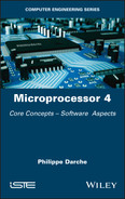
Figure 5.11 shows an example of pre-emption during execution of IT routines.
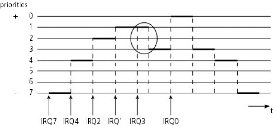
Figure 5.11. Pre-emptive execution in a system of hierarchized interrupts
An acknowledgment is generally sent to a requester when it is seen. One example is MC6809, which indicates using the signals BA (Bus Available) and BS (Bus Status) that reading of a hardware interrupt is underway.
5.2.5. Interrupt controller
The IT controller was initially an external logic or component (EIC for External Interrupt Controller), one example being the 8259A from the 8086 family. This type of component manages ITs in a vectorized manner. We thus speak of VIC for Vectored Interrupt Controller in the Arm® family.
A complex I/O controller can have a dialogue with its processor. For example, the 8086 in association with its external 8259A controller generates two consecutive bus cycles via its INTA (INTerrupt Acknowledge) signal to signify recognition. The first cycle accomplishes the acknowledgment. During the second cycle, the 8259 controller sends the number of the corresponding vector. In the inactive state, this signal can alert the controller to its availability to receive a request. When a controller does not respond during the acknowledgment stage, then the interrupt is called a spurious interrupt and an internal exception is generally raised (case of the MC68000, for example). Figure 5.12 shows the internal logic for considering the request from this controller.
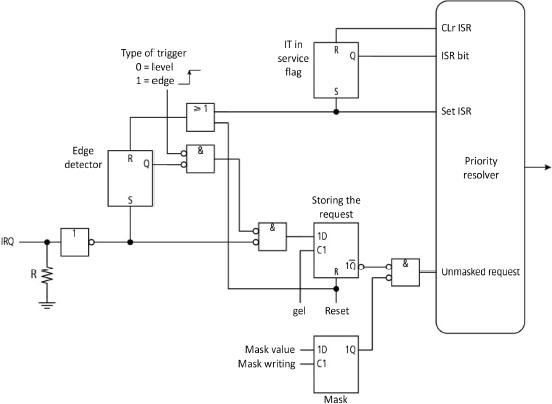
Figure 5.12. Simplified processing logigram of an interrupt from the IT 8259A controller (Intel 1988)
It was first integrated into the southbridge chipset (cf. Chapter 1 in Darche (2003)) and now into advanced MPUs (IIC for Internal Interrupt Controller) as well as in microcontrollers (AVR or PIC (Peripheral Interface Controller/Programmable Intelligent Computer) family, for example). At Intel, it is called APIC for Advanced Programmable Interrupt Controller (cf. § 5.11).
5.3. Nested interrupts
In the case where another request arrives during processing of an interrupt, the same context saving and branching process will be executed. There is no state incoherence since access to the stack is “Last-In, First-Out” (LIFO). The only problem is the size of the stack that stores contexts (of limited depth) and the coherence of the sub-program execution state (possible side-effect if the program is not re-entrant). Interrupts are called nested interrupts or stacked interrupts. Figure 5.13 illustrates an interrupt nesting.

Figure 5.13. Mechanism of nested hardware interrupts
Nested calls should be avoided because of problems with reaction time and starvation. They cumulate the handling times of the execution context (i.e. saving/restoration) and, in the case of a blockage in one of the sub-programs, they can cause starvation, that is, an indefinite waiting time. They complicate the software, are a source of operating errors and do not, in general, improve performances (cf. § 3.4). Fortunately, it is possible to forbid consideration of an IT using the mask interrupt mechanism. Masking the request can delay its acknowledgment. If interrupts are hierarchized, lower ranking requests are masked. Masked does not necessarily mean lost. In the microprocessor status register, there is an indicator (Interrupt Flag or IF) that controls its consideration using programming (authorization or invalidation at state 1 according to implementations). The new request is then registered, but the re-routing is reported until the flag is updated. The interrupt is then called maskable. Internally, a flip-flop then registers the interrupt request. If the sensitivity is of edge type, a loss of request can occur. On the other hand, when the flag is re-initialized, the flip-flop re-enregisters the request that follows. If the interrupt is not maskable, the designer automatically invalidates the interrupt input with or without the possibility of modifying this behavior depending on the implementation. The MPU can also lose an interrupt request if the processing is not fast enough. On the contrary, a critical application in real time cannot accept the loss of an interrupt without the penalty of serious problems in managing the procedure, for example, the destruction of an embedded system such as a rocket.
Another way of processing requests is to queue interrupts. This technique is addressed in § 5.8.
5.4. Internal causes
Interrupt requests (Figure 5.1) originate in specialized instructions (trap), or they come from an execution error (software exception). Hence, we speak respectively of synchronous and exception interrupts. It should be noted that interrupts due to internal causes can always be reproduced, which is not the case with external interrupts, because of their nature.
A software interrupt or trap, occasionally called an internal interrupt, is an event triggered explicitly by a specialized instruction (programmed interrupt). It is therefore a deliberate act by the programmer, which wishes to raise a trap. An instruction such as swi (microprocessor MC6809 (Motorola 1984)), as Figure 5.14 illustrates, explicitly requires a re-routing. This instruction masks IRQs during its execution. There can be a passing of parameters such as the operand with the instructions int (x86 architecture) and trap (MC68000). Interrupt return instructions are the classical iret (interrupt return, x86 architecture, for example) and eret (exception return, MIPS (Microprocessor without Interlocked Pipeline Stages) architecture, for example). These specialized instructions are therefore well adapted to call on an OS' services (system or supervisor call) as the associated routine will be executed in a privileged mode (cf. § 3.2.2) if the MPU offers it, which was not the case with 8-bit generations of that era. It should be noted that Arm® has an instruction swi whose operand format is formed of three bytes, so 224 ISR possible!

Figure 5.14. Call and return of a non-nested software interrupt (example with MC6809)
We find the same concept of nesting requests for external IT (cf. § 5.2), as Figure 5.15 illustrates.

Figure 5.15. Call and return of nested software interrupts (example with MC6809)
Figure 5.16 details the development of the stack following these nested requests.
Figure 5.16. Call and return of nested software interrupts (example with MC6809)
A fault is an event that results from it being impossible to execute an instruction (memory error, problem of execution protection, etc.). An attempt at writing in ROM (Read-Only Memory), an absence of memory at this address (i.e. access in the void), an illegal address or a page fault in physical memory are examples of memory error. It is generally correctable and corrected, for example, by a re-execution of one or more instructions (retries) in the case, for example, from an OS service. As this happens during execution of an instruction, it is possible to define three sub-classes of fault linked to the execution stages (cf. § V1-3.3.2). These are raised after an instruction fetch, at its decoding and at its execution. A software exception can fall into the “fault” class (the most common) or the “abort” class. The abort results from a string of two faults. Intel calls it a “double fault”. It announces a serious problem at the kernel. Table 5.2 classes interrupts in three categories to decide whether there is a double fault or not. It should be noted that the tendency towards integration has meant that external requests that were hardware exceptions of the “abort” type are transformed into software faults. One example is the abort called “coprocessor segment Overrun”, uniquely for the 386, which then became a fault.
Table 5.2. Categories of interrupt to qualify a double fault in 80386 (Intel 1986)
| Categories | no. | Description |
| Benign exceptions | 1 | Step-by-step (debugging) |
| 2 | NMI | |
| 3 | Breakpoint | |
| 4 | Overflow (relative integer) | |
| 5 | Boundary control | |
| 6 | Invalid operation code | |
| 7 | Coprocessor unavailable | |
| 16 | Coprocessor error | |
| Contributing exceptions | 0 | Division error |
| 9 | Coprocessor segment overflow | |
| 10 | Invalid TSS | |
| 11 | Segment not present | |
| 12 | Stack exception | |
| 13 | General protection | |
| Page faults | 14 | Page fault |
Table 5.3 allows us to decide if there is a double fault, considering the causality of IT requests.
Table 5.3. Decision criteria for qualifying a double fault in 80386 (Intel 1986)
| Second exception | ||||
| Benign exception | Contributing exception | Page fault | ||
| First exception | Benign exception | No | No | No |
| Contributing exception | No | Double | No | |
| Page fault | No | Double | Double | |
A fault is automatically generated (we say it is raised) on an abnormal condition during execution of an instruction. A fallible instruction is an instruction that causes an exception. It can result from programming errors or abnormal conditions. It can be a forbidden instruction, one that is impossible to execute or non-existent (undefined operation code). One example is the page or segmentation fault, which is an abnormal and unusual event caused by execution of an instruction. Resuming consists of loading the faulty page or segment and re-executing the instruction. Calculation exceptions involve whole and relative integers or fixed and floatingpoint numbers. For integers, there is the overflow or division by zero. For example, at Intel, overflow is a trap-raised by the instruction into (interrupt on overflow), and so it is wanted by the programmer and is not a fault. For floating point, the R4000 microprocessor has, for example, five exceptions, which are an invalid operation, underflow, overflow, division by zero and inexact result (rounding-off problem). It should be noted that a division by zero that calls an ISR raising the same exception creates an infinite loop.
The difference between a trap and a fault lies at the point of recovery. For the first, it lies in the instruction following the branching, while for the second, it will be situated at the faulty instruction. A TLB failure (Translation Lookaside Buffer, this will be covered in a future book by the author on memories) is a fault. An exception on overflow is a trap. There is no resumption of the program, or the task follows an abort since it involves a serious error.
5.5. Debugging
Debugging an ISR is difficult, since the insertion of a debugging code can influence the system's operation, by slowing it, for example. One particular software interrupt is trace or step-by-step mode where a trap is raised at the end of each execution of an instruction, which will launch a specific debugging routine. To do this, it is necessary that the processor is in a particular execution mode (cf. § 3.2.2). The routine is in fact the debugging program (cf. § V1-2.2.4), which makes it possible among other things to visualize the different memory areas (instructions, data, stack, etc.) and the registers. For 8086, as Figure 5.18 shows, the IF and TF (Trap Flag) flags are set at zero during its execution. This means that it is executed in normal mode and not in step-by-step mode. With this same processor, the breakpoint uses the instruction int 3, which replaces the right instruction placed after the one stopping the execution (patch) and is saved provisionally. The associated routine should save the context, call the debugging program and, at the end, execute the replaced instruction and restore the context to make this break transparent. A hardware aide is often available, either an elementary one such as a Light-Emitting Diode (LED) or a more elaborate one such as a JTAG (Joint Test Action Group) hardware probe (cf. § V5-2.2.5), for example. A final function that the MIPS (Microprocessor without Interlocked Pipeline Stages) microprocessor offers is its EPC register (for Exception Program Counter), which contains the address of the instruction that generated the trap.
5.6. Priority between internal and external interrupts
It is desirable to be able to receive requests from different sources. It is necessary to be able to serve them to define a priority between them. There is a priority between hardware and software interrupts. Figure 5.17 shows the decision organigram. The consideration is called “at the instruction boundary”. Hardware interrupt requests are evaluated before the start of an instruction's execution. They are therefore a priority. The trap is evaluated during its execution. On the contrary, we see here that a trap underway masks future maskable hardware interrupt requests.

Figure 5.17. Decision process from MC6809 (simplified organigram without HALT and Reset modes in particular) from Motorola (1984)
A counter-example is 8086 where software interrupts are priority. Raising them means that the associated ISR is launched at the following cycle. Table 5.4 gives the priorities for different interrupts.
Table 5.4. Priorities of different interrupts from 8086
| Interrupts | Order of priority |
| Division error, int, into | From high |
| NMI | |
| INTR | |
| Step-by-step | To low |
Figure 5.18 shows the corresponding decision organigram. Each request acceptance leads to invalidation of the maskable ITs (IF flag = 0) and of the step-bystep execution mode (TF flag = 0). An additional test is inserted just before the execution of the routine body, so as to know if there has been an NMI request (more priority) since the first test. The variable TEMP makes it possible to save the state of the execution mode, either normal or step-by-step.
The priority chosen for the MPU step-by-step mode leads to an unwanted effect in IT processing that means that the debugging routine is called just before the first instruction of the most prioritized routine. Figure 5.19 gives an example with the processing of a non-maskable interrupt. It should be noted that the unstacking of the CS and IP registers is symbolized in this figure by the word “return”. This side effect can be inconvenient for development since an execution delay or worse, a break, is introduced in the interrupt routine. Hence, in the following generation (i.e. 80286), Intel increased the priority of this mode just behind the division by zero exception (cf. Table 5.5), so before the external interrupts. Processing routines invalidating the step-by-step mode during re-routing are no longer disrupted in their execution. The hardware thus guarantees that the step-by-step execution mode stops when there is a hardware interrupt request so that the associated handling routine is not executed in this mode. If this mode is necessary, it is then necessary to execute an instruction int to execute the corresponding handler.
Figure 5.20 shows the instance of two simultaneous interrupt requests, one internal and non-maskable, and the other external and maskable. This latter is processed after the first and once the return to the main program is made. The drawback cited in the previous case is applied to each interrupt routine.

Figure 5.18. Processing sequence for interrupt requests from 8086 (Intel 1989)

Figure 5.19. Step-by-step execution modes with NMI and normal (Intel 1989)
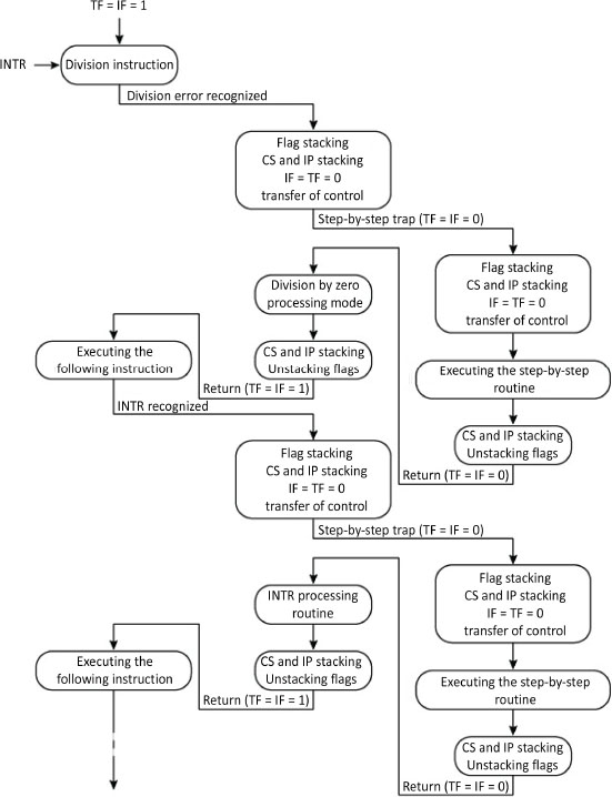
Figure 5.20. Simultaneous software exception and maskable external interrupt interacting with the step-by-step execution mode (Intel 1989)
One exception to all these priorities is the case of three simultaneous requests (Figure 5.21). In this case, the step-by-step mode is not applied to unmaskable routines that are nested. It is applied as before to the routine of the maskable IT. It should be noted that the unstacking of the CS and IP registers is symbolized in this figure by the word “return”.

Figure 5.21. Simultaneous NMI, INTR and division by zero in interaction with step-by-step execution mode (Intel 1989)
To summarize, Figure 5.22 shows an organigram for processing IT programs representative of the first decades of MPUs, that is, the 8-bit generation, which is the MC6809 from Motorola.

Figure 5.22. Processing organigram for interrupts from MC6809 (Motorola 1981, 1983)
5.7. Identification of the source and vectorization
One difficult case is identification of the interrupt source when the line of requests is shared by several interrupt sources. We saw in § 4.1.1 from Darche (2003) that identification could only be done by polling from possible interrupt sources by reading the interrupt request register. It can also be done by hardware polling or daisy chain, by diffusion or by multi-level interrupts.
Almost all modern microprocessors use the technique of vectorizing interrupts that gather all automatic interrupt recognition techniques to be considered and branching by indirection (indirect addressing, cf. § 1.2.3.3) at the routine. With vectorization, the execution flow is directed towards a start address for each interrupt except in the case of auto-vectorization (cf. § above for the latter case). The vectorization mechanism relies on an indirection. Information, making it possible to locate the interrupt routine, is sent to a vectorized interrupt request. It may be an IT address or number. When it is an address (first case) provided in general by the interrupt controller (cf. § 4.1.1 in Darche (2003)), the MPU loads it in the program counter to execute the routine. It is a number (second case), an unsigned integer (format n = 8 bits, for example, for x86 architecture) that serves as a cell index in a table where the routine start address is stored. There are therefore two definitions of a vector depending on the manufacturers or authors. A vector is either the processing routine start address8 called an interrupt (address) vector or also an interrupt pointer, or an unsigned integer that serves as an index in a table (Intel 2003b, 2005) called an ISR lookup table. Each interrupt vector location (i.e. cell) is addressed by the IT number. This vectorization can be internal or external. In the first case, which is rare, this table is in the interior of the microprocessor and the content of the vector is fixed. In the second case, it is found in the random access or read-only memory (i.e. RAM or ROM) or in a specialized controller, and it is modifiable under some conditions (i.e. access rights). As a vector corresponds to each interrupt, recognition of the interrupt source is therefore more effective than sharing the line alone since the mechanism is an integral part of the processor. On the other hand, the number of inputs is limited by a hardware that is costly in the number of pins and this approach is not flexible since the priority policy is fixed.
At consideration, after saving the context, the program counter is loaded with the content of the interrupt vector that contains the start address of the associated interrupt routine. Access to the routine is achieved by indirection. The interrupt vector is consequently a pointer (Figure 5.23). This concept was operated for the first time in the TX-2 computer from MIT Lincoln Labs (Clark 1957). 8-bit MPUs that supported vectorization are the 8085 and the Z80. In the 16-bit version, we list the 80x86. Software interrupts from 8085 are vectorized. Among hardware interrupts (trap, RST 5.5, 6.5 and 7.5), only INTR is not vectorized.
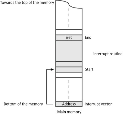
Figure 5.23. Vectorization of the interrupt
The address of the table is specific to each (family of) component(s). The MC680x family has its table of four vectors placed at the top of its address space. Table 5.5 shows the IVT (Interrupt Vector Table) from IA-32 architecture (i.e. x86 architecture in 32-bit version) situated in the memory area, the start address 0000:0000 (Intel 2003a). Each interrupt has a priority called a “type” and an associated vector. The priority defines the order of processing. The table has been completed as new generations appear. The 8086 (Intel 1989), for example, designated vectors no. 5 to 31 as reserved. The 80286 adds seven new interrupts, four for the 80386. Since this MPU's memory is segmented and acts on the real mode (i.e. unprotected), the size of a vector is 4 bytes, including two for the segment (this will be covered in a future book by the author on memories) and two for offset. It should be noted that the Reset vector does not appear in the table as it is placed for most processors generally high in the memory space in a non-volatile memory with start and initialization FirmWare (FW) (cf. § V5-3.5.3). A counter-example is MicroBlaze from Xilinx, which is a “soft processor core” implanted in an FPGA (Field-Programmable Gate Array, cf. § 4.3.2 in Darche (2004)).
Table 5.5. Table of 256 interrupt vectors from IA-32 architecture
| Type (vector no.) | Designation | Origins |
| 0 | Division by 0 | 8086/8088 |
| 1 | Step-by-step mode (debugging) | 8086/8088 |
| 2 | NMI | 8086/8088 |
| 3 | Breakpoint exception | 8086/8088 |
| 4 | Overflow of a relative integer | 8086/8088 |
| 5 | Range limit exceeded | 80286 |
| 6 | Undefined operation code | 80286 |
| 7 | (Unavailable mathematical) coprocessor | 80286 |
| 8 | Double fault | 80286 |
| 9 | Reserved (memory violation of 387 coprocessor) | 80286 |
| 10 | Invalid Task State Segment (TSS) | 80386 |
| 11 | Segment not present (in memory) | 80386 |
| 12 | Stack (segment) fault (limit reached or segment absent in memory) | 80386 |
| 13 | General protection exception (segment boundary exceeded) | 80286 |
| 14 | Page fault exception | 80386 |
| 15 | Reserved | – |
| 16 | Floating-point calculation error (x87) | 80286 |
| 17 | Alignment-checking exception (memory) | 80486 |
| 18 | Computer control exception | Pentium Pro |
| 19 | SIMD floating-point calculation error (instructions SSE and SSE2) | IA-32 |
| 20–31 | Reserved | – |
| 32–255 | Available for the user | 8086/8088 |
Note that for the first microprocessors or for some interrupts such as IntR, automatic presentation of the IRQ vector happens via an external module (Figure 5.24), the IT controller and not by reading the table of vectors, according to a defined protocol.

Figure 5.24. External vectorization
One variant is the presentation of an operational code instead of a vector. For example, we cite the MPU Z80 from Zilog, which has three maskable IT management modes for compatibility reasons and because of the possibilities offered. The first (no. 0) is Intel 8080 mode where an external controller provides an instruction code of one byte, generally rst (restart, that is, the equivalent of a call) making it possible to branch at one of eight locations (8 bytes long) starting from the memory address space (page 0) where the corresponding ISR is found. Mode no. 1 executes an instruction rst with 0038h as a start address, which is equivalent to an NMI processing but at a different address from the one normally linked to it (= 0066h). The last, the most powerful mode, makes it possible to make an indirect call to a routine placed anywhere in the memory space from a vector formed from 8 bits provided by the controller (LSB for Least Significant Byte) and from the content of a register named I (MSB for Most Significant Byte) that addresses a table's cell in 16-bit format containing the ISR address (starting location).
There is a table variant that does not contain the vector but contains the routine code directly (PowerPC 9 and Arm® approaches). Since the available size is small (8 bytes for the (MCU for MicroController Unit) 8051 microcontroller from Intel, RESET aside), the cell generally only contains one jump instruction to an associated routine, since it is constrained by memory space (size of one jump instruction or an instruction from the routine itself). The table was called a jump table. One advantage is that the cell can contain the instructions nop or a jump to the following cell, enabling a fall-through approach. A second advantage is a faster handling since there is no indirection.
MC68000 has many useful functionalities such as auto-vectorization. This term means that an IT controller too simple or old to provide a vector can benefit from vectorization. To do this, the MPU itself generates a vector depending on the priority of the given request on its inputs, called an Interrupt Priority Level or IPL[2:0], the number of the basic vector and their number fixed by the manufacturer (respectively = 1916 and 8).
In the first microprocessors, which positioned indicators at the end of execution, the state of these latter should be explicitly tested so as to be able to process the exception. Others can raise the exception automatically.
One original approach is that of MIPS (Microprocessor without Interlocked Pipeline Stages), which does not use vectorization. It stores the type of interrupt pending in a cause register (Hennessy et al. 1982), speaking of the surprise register, containing an identification code for the origin of the interrupt in the format n = 4 bits. Table 5.6 shows its different values for MPUs R2000, R3000, R4000 and R6000. The benefit is that it makes handling of interrupts orthogonal to handling of instructions. It becomes uniform regardless of its type. Requests can be processed by a centralized routine, which can make the vector table useless. The drawback is that the processing is slower than with the solution that uses a vector table. It should be noted that this MPU's status register does not have classical status flags (NZVC, cf. § V3-3.1.5.1). A counter-example is the COP8 microcontroller (from NS), which uses a general fixed address management routine (i.e. 00FFh), of which the first instruction is vis (1-byte format). The latter determines the cause of the interrupt, making it possible to address a cell from a 16-vector table, and then makes an indirect jump to the corresponding management routine.
Table 5.6. List of exception codes (ExcCode) for MIPS architecture (Kane 1988; Kane and Heinrich 1992)
| Number | Mnemonic | Description |
| 0 | Int | External interrupt (i.e. hardware) |
| 1 | Mod | TLB modification exception (cache) |
| 2 | TLBL | TLB reading failure exception (reading or fetching an instruction) |
| 3 | TLBS | TLB writing failure exception |
| 4 | AdEL | Address error exception (reading or fetching an instruction) |
| 5 | AdES | Address error exception (writing) |
| 6 | IBE | Bus error exception for fetching an instruction |
| 7 | DBE | Bus error exception for a data reading or writing |
| 8 | Syscall | Call system exception |
| 9 | Bp | Breakpoint exception |
| 10 | RI | Reserved instruction exception |
| 11 | CpU | Unusable coprocessor exception |
| 12 | Ov | Arithmetical overflow exception |
| 13 | Tr | Trap (R4000 and R6000 only) |
| 14 | NCD | LDCz/SDCz (writing/reading in/of the processor) towards an un-cached address (R6000 only) |
| 14 | VCEI | Virtual coherence exception instruction (R4000 only) |
| 15 | MC | Computer control exception (R6000 only) |
| 15 | FPE | Floating-point exception (R4000 only) |
| 16–22 | - | Reserved for future use |
| 23 | WATCH | Reference to the address stored in the registers WatchHi/WatchLo (R4000 only) |
| 19–30 | - | Reserved for future use |
| 31 | VCED | Virtual coherence exception data (R4000 only) |
Figure 5.25 shows two possible implantations of an IT system (vector table at the start of the address space). The vectors in the table are initialized by initializing the system in the case of storage in Random Access Memory (RAM). If the system has a monitor (cf. § V5-2.2.4.1), the IT table will be with it.

Figure 5.25. Two typical implantations of different memory areas of an IT system
5.8. Nested and queued interrupts
Simultaneous processing can generate many problems. One example is a division by zero that triggers a routine that, itself, executes a division by zero, therefore triggering an infinite loop. System programmers avoid having to process these cases by raising the double fault exception for example, which will halt the program or the faulty process, and by signaling the error. Externally, apart from critical hardware exceptions that require halting the machine, requests are generally masked during an IT processing. However, they should not be lost.
Simultaneous requests can be made using nested interrupts (cf. § 5.3). When the number of IT sources is high, it becomes difficult to assign a vector and a routine to each of them. Moreover, if requests are not processed fast enough, there is a risk that requests will be lost. One solution is to put in place a message queue, each message encapsulating a request (queued interrupts). It is useful to put requests in a queue as it serializes requests and their associated processing. The drawback is that it is impossible to raise another interrupt if one is being handled; it will be queued like the others. As Figure 5.26 illustrates, the IT service routine manages the role of transmitting messages and a process manages them.
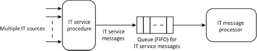
Figure 5.26. Proposal for processing flow for many IT requests (Intel 1980)
This technique does not pose any problems as long as the source is external. There is no causal link between them. In the case of internal ITs, the same is true if an internal IT is underway and an external request arrives. In the two other cases, nested management is obligatory. In fact, as the source is an instruction execution, programmed interrupt or exception, it is necessary to process it before returning to the previous one. Walker and Cragon (1995) summarized all the cases using Table 5.7.
Table 5.7. Management options in the case of multiple IT processing
| Interrupt underway | IT request to be processed | Management options |
| External | External | Nesting, queueing |
| External | Internal | Nesting |
| Internal | External | Nesting, queueing |
| Internal | interne | Nesting |
5.9. Uses
Hardware interrupts were first used mainly for I/Os as they mean the microprocessor does not lose time (i.e. active waiting) to detect possible external events, for example, end of I/O transfer, using the polling technique (cf. § 4.2.1 in Darche (2003)). It is the I/O controllers that generate these maskable requests, and they are processed by OS drivers. But beware, the interrupt mechanism is not always the best solution for handling I/Os. Polling or a hybrid solution can give better performances (cf. Pajari 1989; Yang et al. 2012) studied this subject in the framework respectively of a serial interface and of block mode transfers in the (mass) storage domain. The interrupt is also used to indicate a major hardware error. The MPU is generally put in halt mode while waiting for a hardware initialization (reset).
Modern OSs make massive use of software interrupt request instructions to call their services and exceptions to manage faults and aborts. Software interrupts are usually encapsulated in a function of a High-Level programming Language (HLL). Calls to operating system services are made by a trap, making it possible to change from execution (user/supervisor) mode. Within the OS, the exceptions are transformed into signals that are sent to processes, for example, by calling on the “kill()” function in UNIX OSs. Task switching is triggered according to the rhythm of the interrupt requests from the timer. We recall that this controller has a (de)counter/timer that generates interrupt requests. For a presentation of the latter, see § 3.3.1 in Darche (2003). The exceptions make it possible to detect execution errors, in particular calculation errors (overflow, division by zero, etc.). Modern MPUs detect illegal or invalid instructions (cf. § 3.1.1) and generally raise a trap that will reroute the execution towards an exception handling routine (the case of the Arm® family, for example). The MC68000 detects an instruction machine code that has not been implemented by raising exceptions named line A and line F, the latter being the hexadecimal figure corresponding to the binary words detected (first byte of the operational code). Misuse involves setting a breakpoint (cf. § V5-2.2.2) and emulating an instruction of an absent mathematical coprocessor. More details are given in Clements (1997). Table 5.8 summarizes the resolution.
In microcomputers before 2010, interrupt management routines belonged to a BIOS (Basic Input Output System, cf. § V5-3.5.3) that was stored in a read-only memory (FirmWare or FW). The concept of interrupt is essential today in the domain of embedded systems. In its absence, development of this type of application would be excessively complex.
Table 5.8. Table summarizing interrupts

5.10. Interrupts and execution modes
Microprocessors, since the 16-bit generation, have considered execution mode (cf. § 3.2.2) in handling the interrupt request. Therefore, interrupts are executed classically in three modes, privileged (or protected), user and real (address). Table 3.3 shows execution modes from Arm® architecture. It integrates the classic interrupt modes IRQ and fast FIQ as well as abort mode. There is in fact an execution mode for a type of interrupt. On consideration, control transfer is effected at the same priority level or at a higher level of privilege but never at a lower level. An attempt at execution of a privileged instruction or one with a particular privilege in a mode with less privilege causes an exception.
It is necessary to protect the IT Vector Table (IVT) since an interrupt can be diverted from its processing routine by a malicious program such as a virus, for example, as was possible, for example, with the 8086. At Intel, there is an IVT in protected mode named Interrupt Descriptor Table (IDT) where each vector is supplemented by flags. Unlike its counterpart, it can be implanted anywhere in the address space thanks to the IDTR (IDT Register) that contains its start address that is modifiable thanks to the lidt instruction (load interrupt descriptor table register). Each input (8 bytes in IA-32 architecture) contains a gate descriptor, either of a task, and interrupt or a trap.
5.11. Interrupts and advanced architectures
Modern architectures, to improve execution time, integrate processing units that operate in series (pipeline) and in parallel (superscalar architecture). These microarchitectural approaches are described in detail in the second volume. Also, this section is only an introduction, which will be completed later.
In a monoprocessor architecture without a pipeline, considering only internal interrupts and supposing that the interrupt handlers (ISR) cannot generate interrupt requests (i.e. fault-free handler), managing the context is simple and there is at most only a single instruction to re-execute (in case of fault). Table 5.9 shows recovery points for the classic ITs of a classic MPU. One serious error is a hardware breakdown or an erroneous system table. There is therefore no recovery. Some errors provide an error code, useful for a potential retry or for a debugging.
Table 5.9. Interrupt recovery points for the 80286
| Interrupt names | Classes | IT no. | Instructions involved | Restart points | Error on the stack |
| Division by zero | Fault | 0 | div, idiv | At the instruction in question | No |
| Step-by-step | Hardware trap (!) | 1 | All | Following instruction | No |
| NMI | IT hardware | 2 | int 2, all | Following instruction | No |
| Breakpoint | Trap | 3 | int 3 | Following instruction | No |
| Overflow (integers) | Trap | 4 | int 4, into | Following instruction | No |
| Extent boundary exceeded (boundary control) | Fault | 5 | int 5, bound | At the instruction in question | No |
| Invalid operation code | Fault | 6 | Undefined | At the instruction in question | No |
| MPU extension of (coprocessor) unavailable | Fault | 7 | esc, wait | At the instruction in question | No |
| Reserved (Intel) | – | 8–15 | – | – | – |
| MPU extension error | Fault | 16 | esc, wait | – | – |
| Reserved (Intel) | – | 17–31 | – | – | – |
| Defined by the user (i.e. available for) | Trap | 32–255 | int | Following instruction | – |
Table 5.10 shows the restart points in real mode for the same MPU.
Table 5.10. Recovery point for ITs for the 80286 (real mode)
| Interrupt name | Classes | IT no. | Instructions involved | Restart points |
| Limit of an interrupt table that is too small | Abort | 8 | – | At the instruction in question |
| Segment overflow from the coprocessor | Fault | 9 | esc with a too high operand address | At the following instruction |
| Segment overflow | Fault | 13 | With a too high memory address | At the instruction in question |
Table 5.11, following the two previous tables, does this for protected mode. The column called “restart” indicates whether the program/process can continue or should be stopped.
Table 5.11. Recovery point for ITs for the 80286 (protected mode)
| Interrupt names | Classes | IT no. | Possible restart | Restart points | Error code on the stack |
| Double fault | Abort | 8 | No | At the instruction in question | Yes (= 0) |
| Segment overflow of the coprocessor | Abort | 9 | No | Following instruction | No |
| Invalid task state segment | Fault | 10 | Yes | At the instruction in question | Yes (= TSS at fault or selector) |
| Segment not present | Fault | 11 | Yes | At the instruction in question | Yes (= descriptor selector) |
| Stack segment overflow or stack segment not present | Fault | 12 | Yes | At the instruction in question | Yes (= segment selector or 0) |
| General protection | Abort | 13 | No | At the instruction in question | Yes (= descriptor selector) |
It is not the same with parallel architectures. Several instructions are issued in parallel and can also be executed in parallel. First, it is necessary to define what sequential and serial executions are. An execution is called sequential if each instruction is executed completely before execution of the next is launched. This was true for the first MPUs. A serial instruction execution is an execution that respects their order of arrival. The MPU's state change follows the same order. This is the case with a pipeline processor. But such a processor does not carry out a sequential execution.
Several interrupt requests can therefore be generated internally, to which several external requests can be added. Except for an external interrupt and RESET aside, consideration does not only occur at the instruction boundary but can be done between the different sub-steps in the execution cycle. During interrupts, these architectures generate additional execution time costs that may be prohibitive. For example, in a pipeline, when an interrupt request is effective, it may be necessary to terminate execution of instructions engaged in the pipeline to facilitate recovery of the interrupted thread. Walker (1992) thus defines six stages in managing interrupts for pipelined architectures. These are detection, termination of the instruction underway, cancelation of the execution (pipelined architecture), saving the context, execution of the handler and restarting of the interrupted process. It is then necessary to define the concepts of precise and imprecise interrupts.
Interrupts as they were described previously, that is, for a single processor without an accelerator mechanism, are called precise. For them to be so, three conditions should be met for the execution to continue correctly (Smith and Pleszkun 1988). First of all, all the instructions preceding the instruction being executed at the moment of the interrupt request should be executed and they should have modified the state of the process correctly. Those that should follow should not be executed and should not modify the state of the process. To finish, if the interrupt request is caused by an instruction, this should be executed completely, for example, during an overflow, or it should not or cannot be executed at all (e.g. in the case of a page fault). The state of the process before a precise interrupt is called serially correct, that is, identical to a sequential execution (Walker and Cragon 1995). This state can be the one before or after the execution in question. It will not be sequentially correct during a precise interrupt. The precise interrupt is used if the state of the processor should be rebuilt, for example, in the case where the software should repair the error that caused the interrupt request and should allow recovery of execution. If the cause is external, recovery is easy. For an internal cause, this may be costly in terms of time in the case of a parallel hardware environment (pipeline and superscalar architecture). But this type of interrupt is needed in mechanisms such as the memory page fault (this will be covered in a future book by the author on memory) or requested by the IEEE 754 standard (Hennessy and Patterson 2017) that concerns calculation in floating point in base 2 (IEEE 1985, 2008) (for the associated representation, cf. § II.4.2 in Darche (2000)). Therefore, the interrupt model for floating-point calculation units (FPU for Floating-Point Unit) is most of the time of a precise type. A counter-example is the PowerPC family (Motorola 1996). With this family, the programmer can choose the exception mode from among four for calculation in floating point. An imprecise interrupt means that the instruction following the one that produced the exception may be terminated or in the process of being executed. The state at this instant is fragmented but recoverable (Grohoski 1990), that is, restorable albeit with a time cost. The choice of this type of interrupt is therefore guided by a gain in performances. A microprocessor such as Alpha from Digital Equipment Corporation (DEC) may have some precise interrupts and others that are not precise (Compaq 2002). Samadzadeh and Garanabi (2001) study five management strategies for this type of execution. For more information on this subject, see also Moudgill and Vassiliadis (1996) and Rudd (1997).
The serialization of interrupt requests in parallel environment will consist of ensuring that they are processed sequentially. This is one of the roles of the interrupt controller (cf. § 4.1.1 in Darche (2003)).
In a superscalar architecture, the processor is capable of launching and withdrawing (i.e. end of execution) several scalar instructions per cycle (multiple- issue processor). The result is that they can be executed in parallel. Hence, they were first called look-ahead processors (Rau and Fisher 1992, 1993), that is, a processor with anticipated execution. The instructions are provided sequentially, and it is the internal hardware that is responsible for their distribution on different functional units. Other than the IT software already mentioned, the generation of requests and consideration of exceptions can only be done during speculative execution of an instruction. Consideration should therefore be deferred. One solution is to carry out speculative execution only for instructions that do not raise an exception (safe speculation). Another approach is boosting (Smith et al. 1992; Smith 1992), which consists of labeling the instruction to “boost” with a bit called a reservation enabling the MPU to decide whether an instruction should be re-executed. A state information is saved until execution of another path. Another solution is the poison bit (Hennessy et al. 1982). The schema of the poison bit consists of attaching the aforementioned bit to the result register of destination register with the idea of reporting an event. When a trap is raised following an execution, the poison bit of the register is positioned, but the exception does not take place. On the contrary, if, afterwards, an instruction reads this register, then this exception takes place. Walker and Cragon (1995) study ITs in pipelined and superscalar environments.
To succeed to monoprocessor architecture and the classic 8259A controller from Intel, in a multiprocessor environment, interrupt control functions were distributed between the microprocessors and I/O controllers. In the case of Pentium, a specialized bus called ICC (Interrupt Controller Communications) makes it possible to make different APIC (Advanced Programmable Interrupt Controller) controllers communicate with one another. Each controller receives interrupt requests linked to its node (LINT for Local INT) and, via the bus (APIC or ICC bus), transmits and receives, in particular, requests from other UCs to be able to handle the IT (Figure 5.27, and cf. § 4.1.1 in Darche (2003)). The local controller was integrated for the first time in the Pentium P54C (1954). The architecture includes an external controller called I/O APIC (IOAPIC) under the reference 82489DX. In this architecture, it is necessary to distinguish two types of processor, which are the starting microprocessor (BSP for BootStrap Processor) and the application processor (AP). Other versions followed, such as 82093AA and the xAPIC architectures and its extension, x2APIC respectively appeared with the Pentium 4 MPU (microarchitecture NetBurst – 2000) and the Nehalem microarchitecture (2008). Interrupts in a multicore environment will be studied in a future book by the author.

Figure 5.27. Organization of different APICs
To summarize, Tables 5.12 (a) and (b) show a list of the most common interrupts by specifying their properties. The term “voluntary” means choosing a programmer. This is an explicit request by instruction, which is different from unwanted requests, that is, constrained or submitted requests. An additional column would have been one that indicated a program stop, or indeed a stopping of the machine or a continuation or recovery, at the level of the instruction or the following one. The term is terminate/restartable–resume–continue. Instances of breaks are cases of serious problems such as, at hardware level, a major failure or an imminent power cut, or at software level, a double fault or an undefined instruction. A final criterion may also be whether the IT request can be nested (cf. § 5.3) and/or placed in a queue (cf. § 5.8).
Table 5.12a. Suggestion for classification criteria according to Hennessy and Patterson (1990) and Walker (1992)
| Types | External (E)/internal (I) | Synchronous (S)/asynchronous (A) | Voluntary (V)/constraint (C) | Between instructions (E)/internal to the instruction (I) |
| Hardware malfunction | E or I | A | C | I |
| I/O request | E | A | C | E |
| Bus error | E | A | C | E |
| Memory error | E | A | C | E |
| Power failure | E | A | C | I |
| System call (trap) | I | S | V | E |
| Step-by-step mode (execution trace mode) | I | S | V | E |
| Breakpoint | I | S | V | E |
| Overflow (integer number) | I | S | C | I |
| Over- and under-flow (floating number) | I | S | C | I |
| Formatting error | I | S | C | I |
| Invalid instruction | I | S | C | I |
| Undefined instruction | I | S | C | I |
| Memory protection violation | I | S | C | I |
| Misaligned memory access | I | S | C | I |
| Page fault | I | S | C | I |
| Segment fault | I | S | C | I |
| Privilege violation | I | S | C | I |
| Stack fault | I | S | C | I |
| Double fault | I | S | C | I |
The following table continues this presentation of classification criteria.
Table 5.12b. Suggestion of classification criteria according to Hennessy and Patterson (1990) and Walker (1992)
| Types | Precise (P)/ imprecise (I) | Simple level(S) /multi-level (M) | Maskable (M) or not (NM) |
| Hardware dysfunction | I | S | NM |
| I/O request | P | M or S | NM/M |
| Bus error | I | S | NM |
| Memory error | I | S | NM |
| Power failure | I | S | NM |
| System call (trap) | P | M or S | NM |
| Step-by-step mode (execution trace mode) | P | M or S | M |
| Breakpoint | P | M or S | M |
| Overflow (whole number) | P or I | M or S | M |
| Over- and under-flow (floating number) | P/I | M or S | M |
| Formatting error | I | S | NM |
| Invalid instruction | P or I | S | NM |
| Undefined instruction | I | S | NM |
| Memory protection violation | I | S | NM |
| Unaligned memory access | I | S | M |
| Page fault | P | M or S | NM |
| Segmentation fault | P | M or S | NM |
| Privilege violation | I | S | NM |
| Stack fault | I | S | NM |
| Double fault | I | S | NM |
5.12. Conclusion
This chapter took the subject of interrupt mechanisms. It was first invented to process an overflow problem. It was then used to optimally manage I/Os by avoiding the polling technique.
Interrupts internal to the MPU are either requested explicitly by an instruction (trap) or linked to a problem during the execution (exception). A classification was suggested, and the operation of these hardware and software interrupts has been detailed. The causes of internal then external interrupts have been detailed. The study was pursued with the presentation of different associated aspects such as nested requests, request priority and vectorization.
This chapter ended with execution modes and advanced architectures. In fact, the interrupt mechanism is used in a general way in modern OSs and embedded systems. Having first addressed instruction parallelism or ILP (Instruction-Level Parallelism) and the virtual memory mechanism, this IT concept will be completed in the following volumes by following the development of architectures.
- 1 Kuck (1978) dates the concept to Babbage's analytical engine (cf. § V1-1.1), which stopped by requesting human intervention using a bell (the routine!) when the wrong program card is inserted.
- 2 In some works such as Dumas II (2006), Harris and Harris (2007) and Hamacher (2012), it is the reverse.
- 3 The meaning of this term varies depending on the authors and designers.
- 4 This name for an exceptional event is relative, quite clearly, to the context in which it is situated.
- 5 An error indicates the part of a state that is not correct (Melliar-Smith and Randell 1977).
- 6 Intel calls this an “exception”.
- 7 In a multi-programming context, we would speak about a process or task.
- 8 The definition was retained for this book.
- 9 PowerPC for Performance Optimization With Enhanced RISC Performance Computing.