
Pipeline state objects in a pipeline are the means by which the hardware settings of the physical devices are controlled. There are various types of pipeline state objects specified in the pipeline; which work in a predefined order. The input data and resources in these stages are subjected to changes in line with user-specified behavior. Each stage processes the input and passes it on to the next one. Depending upon application requirements, the pipeline state stage can be bypassed as per the user's choice. This is entirely configurable through VkComputePipelineCreateInfo.
Let's have an overview of these pipeline state objects before we cover them in detail:
- The dynamic state: This specifies the dynamic states used in this pipeline
- The vertex input state: This specifies the data input rate and its interpretation
- The input assembly state: This assembles the vertex data into the primitive's topology (line, point, and triangle variants)
- The rasterization state: This operation is related to rasterization, such as polygon fill mode, front facing information, culling mode information, and so on
- The color blend state: This specifies the blending factor and operation between the source and destination fragments
- The viewport state: This defines viewports, scissors, and dimensions
- The depth/stencil state: This specifies how to carry out the depth/stencil operation
- The multisampling state: This controls the samples to be used in pixel depiction during the rasterization for anti-aliasing purposes
The following diagram specifies each stage in the PSO:

In the following subsections, we will discuss each stage in detail. We will cover the concept of pipeline states, their official specification, and sample code implementation.
We will implement all the pipeline state objects in VulkanPipeline class inside the createPipeline() function. This function first sets up the pipeline state objects, these objects are used to create the graphics pipeline.
The dynamic state specifies the total number of dynamic states used in the present pipeline and their respective objects in the pipeline. It includes the viewport, stencil, line widths, blending constants, stencil comparison masks, and so on. Each dynamic state in Vulkan is represented using the VkDynamicState enum.
The following is the syntax of the dynamic state API:
typedef struct VkPipelineDynamicStateCreateInfo {
    VkStructureType                      sType;
    const void*                          pNext;
    VkPipelineDynamicStateCreateFlags    flags;
    uint32_t                             dynamicStateCount;
    const VkDynamicState*                pDynamicStates;
} VkPipelineDynamicStateCreateInfo;
Let's look at the various fields of this structure:
|
Parameters |
Description |
|
|
This field specifies the type of the current structure. The value of this field must be |
|
|
This could be a valid pointer to an extension-specific structure or |
|
|
This is a reserved field for future use. |
|
|
This refers to the count of |
|
|
This is an array of |
In the next subsection, we will use this API and implement dynamic states.
The very first pipeline state implemented in the VulkanPipeline::createPipeline() function is the dynamic state. First, it creates an empty array of VkDynamicState called dynamicStateEnables and fills it up with the dynamic states. This array informs the pipeline about those states that can be changed at runtime. For example, the following implementation contains two dynamic states: viewport (VK_DYNAMIC_STATE_VIEWPORT) and scissor (VK_DYNAMIC_STATE_SCISSOR). This implementation specifies the viewport and scissor parameters and that they can be changed at runtime.
The dynamicStateEnables is pushed into the VkPipelineDynamicStateCreateInfo control structure object, which will later be consumed by pipelineInfo (VkGraphicsPipelineCreateInfo) to create the graphics pipeline. The following is the code implementation:
    /********** VulkanPipeline.cpp /**********/

    // Inside VulkanPipeline::createPipeline()

    // Initialize the dynamic states, initially it's empty
    VkDynamicState dynamicStateEnables[VK_DYNAMIC_STATE_RANGE_SIZE];
    memset(dynamicStateEnables, 0, sizeof (dynamicStateEnables));

    // Specify the dynamic state information to pipeline through

    // VkPipelineDynamicStateCreateInfo control structure.
    VkPipelineDynamicStateCreateInfo dynamicState = {};
    dynamicState.sType                 =
    VK_STRUCTURE_TYPE_PIPELINE_DYNAMIC_STATE_CREATE_INFO;
    dynamicState.pNext                 = NULL;
    dynamicState.pDynamicStates  = dynamicStateEnables;
    dynamicState.dynamicStateCount     = 0;

    // Specify the dynamic state count and VkDynamicState enum

   // stating which dynamic state will use the values from dynamic

    // state commands rather than from the pipeline state creation info.
    dynamicStateEnables[dynamicState.dynamicStateCount++]      =
                            VK_DYNAMIC_STATE_VIEWPORT;
    dynamicStateEnables[dynamicState.dynamicStateCount++]      =
                            VK_DYNAMIC_STATE_SCISSOR;
Once the dynamic states are constructed, we can go ahead and build the next pipeline state object. The next stage in this process is the vertex input stage, which is described in the following section.
The vertex input state specifies input binding (VkVertexInputBindingDescription) and vertex attribute descriptors (VkVertexInputAttributeDescription). Input binding helps the pipeline access the resource through the binding at the rate at which the data is consumed. On the other hand, the vertex attribute descriptor stores important information such as the location, binding, format, and so on. This is used to interpret vertex data. For more information, refer to the Implementing the buffer resource - creating the vertex buffer for the geometry section in Chapter 7, Buffer Resource, Render Pass, Framebuffer, and Shaders with SPIR-V.
The preceding information is wrapped into the VkPipelineVertexInputStateCreateInfo structure object, which will be used later to create the graphics pipeline. For a detailed explanation of this structure, refer to the following specification. Here's the syntax of this structure:
typedef struct VkPipelineVertexInputStateCreateInfo {
    VkStructureType            sType;
    const void*                pNext;
    VkPipelineVertexInputStateCreateFlags flags;
    uint32_t               vertexBindingDescriptionCount;
    const VkVertexInputBindingDescription*
                           pVertexBindingDescriptions;
    uint32_t                     vertexAttributeDescriptionCount;
    const VkVertexInputAttributeDescription*
                           pVertexAttributeDescriptions;
} VkPipelineVertexInputStateCreateInfo;
The following table specifies each field of this control structure:
|
Parameters |
Description |
|
|
This is the type information of the structure. It must be specified as |
|
|
This could be a valid pointer to an extension-specific structure or |
|
|
This field is reserved for future implementation. |
|
|
This is the total number of vertex binding instances specified in the |
|
|
This is a pointer to an array of |
|
|
This is the total number of vertex attribute descriptions specified in the |
|
|
This is a pointer to an array of |
Let's understand the implementation of the vertex input state in the following subsection.
In the VulkanPipeline::createPipeline() function, the vertex input states are implemented as demonstrated in the following code. This state helps the pipeline understand how the data sent will be interpreted using the vertex attribute descriptions specified in the VkVertexInputAttributeDescription object. Another piece of information it contains is the rate at which the vertex data will be consumed for processing, which is specified in the input binding description (VkVertexInputBindingDescription). There are two ways in which the data can be consumed: per-vertex or per-instance basis. The last createpipelines argument drawableObj (of the type VulkanDrawable) contains the vertex attribute descriptions and vertex input binding description:
     /********** VulkanPipeline.cpp **********/

     // Inside VulkanPipeline::createPipeline(VulkanDrawable*

     // drawableObj, VkPipeline* pipeline, VulkanShader*

    // shaderObj, VkBool32 includeDepth, VkBool32 includeVi)
    VkPipelineVertexInputStateCreateInfo vertexInputStateInfo = {};
    vertexInputStateInfo.sType                           =
       VK_STRUCTURE_TYPE_PIPELINE_VERTEX_INPUT_STATE_CREATE_INFO;
    vertexInputStateInfo.pNext                           = NULL;
    vertexInputStateInfo.flags                           = 0;
    vertexInputStateInfo.vertexBindingDescriptionCount   = 1;
    vertexInputStateInfo.pVertexBindingDescriptions      =
       &drawableObj->viIpBind;
    vertexInputStateInfo.vertexAttributeDescriptionCount = 2;
    vertexInputStateInfo.pVertexAttributeDescriptions    =
                                          drawableObj->viIpAttrb;
Following the vertex input state, we have the input assemble state. This stage assembles the incoming data into meaningful shapes with the help of basic primitives, such as a point, line, or triangle.
When the graphics pipeline receives the vertex data, it is very similar to a bucket filled with unassembled Lego bricks. These vertices are connected in the form of point, line, and triangle variants to give any arbitrary shape as per the user specification. This shape then affects the rasterization stage to produce the corresponding fragments associated with the shape primitives. This whole process is similar to assembling Lego bricks to make a sensible geometrical shape out of them.
These vertices assemble into primitives at a stage called input assembly, which is specified using the VkPipelineInputAssemblyStateCreateInfo structure. This contains the necessary primitive topology information to help vertices to connect with each other, based on the rules specified. The input assembly structure specifies the topology in the VkPrimitiveTopology structure. Refer to the following syntax and the implementation:
typedef struct VkPipelineInputAssemblyStateCreateInfo {
    VkStructureType                          sType;
    const void*                              pNext;
    VkPipelineInputAssemblyStateCreateFlags  flags;
    VkPrimitiveTopology                      topology;
    VkBool32                                 primitiveRestartEnable;
} VkPipelineInputAssemblyStateCreateInfo;
Let's look at the various fields of this structure:
|
Parameters |
Description |
|
|
This is the type information of this control structure. It must be specified as |
|
|
This could be a valid pointer to an extension-specific structure or |
|
|
This field is reserved for future implementation. |
|
|
This field specifies the type of the primitive topology being used, using the |
|
|
This Boolean flag determines whether a special marker or vertex index is used as the primitive restart feature. The special index value should either be |
Specify the primitive topology for the drawing object using the VkPipelineInputAssemblyStateCreateInfo function in VulkanPipeline::createPipeline(). In the following implementation, we used VK_PRIMITIVE_TOPOLOGY_TRIANGLE_LIST, which uses a set of three vertices to produce a filled triangle. Next, we specify whether the primitive restart feature is enabled or not:
     /********** VulkanPipeline.cpp /**********/

    // Inside VulkanPipeline::createPipeline()
    VkPipelineInputAssemblyStateCreateInfo inputAssemblyInfo = {};
inputAssemblyInfo.sType = VK_STRUCTURE_TYPE_PIPELINE_INPUT_-  ASSEMBLY_STATE_CREATE_INFO;
    inputAssemblyInfo.pNext      = NULL;
    inputAssemblyInfo.flags      = 0;
    inputAssemblyInfo.primitiveRestartEnable = VK_FALSE;
    inputAssemblyInfo.topology   =VK_PRIMITIVE_TOPOLOGY_TRIANGLE_LIST;
Let's understand what primitive restart is in detail.
Primitive restart are applicable to only index geometries and used with (vkCmdDrawIndexed and vkCmdDrawIndexedIndirect) drawing APIs.
This feature uses a special marker in a single index array data to recognize disconnected geometries of the same drawing type in a single batch. This is useful in cases where you may have multiple small drawing geometries with a low number of vertices; these multiple geometries can be combined into one index array with each geometry separated using the special reset marker.
The marker used by the primitive restart feature to separate geometries is the highest value of the data type unsigned short (0xFFFF (65535)) or unsigned int (0xFFFFFFFF (4294967295)); with these, the element index array is specified:
- Applicable topology: The primitive restart feature is applicable in the following topologies; the key rule to remember is that it is not applicable on list-type primitive topologies. For more information on topologies, refer to the next section, Primitive topologies:
VK_PRIMITIVE_TOPOLOGY_LINE_STRIPVK_PRIMITIVE_TOPOLOGY_TRIANGLE_STRIPVK_PRIMITIVE_TOPOLOGY_TRIANGLE_FANVK_PRIMITIVE_TOPOLOGY_LINE_STRIP_WITH_ADJACENCYVK_PRIMITIVE_TOPOLOGY_TRIANGLE_STRIP_WITH_ADJACENCY
- Usage: The primitive restart feature can be used by enabling the
primitiveRestartEnablefield (withVK_TRUE) of theVkPipelineInputAssemblyStateCreateInfostructure and specifying a valid topology in thetopologyfield of the same structure.
Let's see the effect of primitive restart on a triangle strip topology. The following diagram uses a set of 11 continuous indices to draw a long and single geometry shape. These indices do not contain any primitive restart markers:

However, interestingly, when the 5th index (4) is replaced using the primitive restart marker 0xFFFF, then it divides this single index list into two. The first half (left of the reset marker) is a new geometry shape that is disconnected from the second half (right of the reset marker), producing another new shape. The Vulkan implementation marches through the start of the index list; when it finds the reset marker, it disconnects the visited indices from the rest of the list and treats them as a separate index list to form a new disconnected shape, as shown in the following image:

In the next section, we will understand the Vulkan topology and learn about the basic primitives: point, line, and triangle and their related variants.
The primitive topology defines the rules that are applied to connect the vertices to produce arbitrary shapes. These shapes comprise a single or several basic primitives: points, lines, and triangles. A primitive topology is specified using VkPrimitiveTopology:
typedef enum VkPrimitiveTopology {
VK_PRIMITIVE_TOPOLOGY_POINT_LIST = 0,
VK_PRIMITIVE_TOPOLOGY_LINE_LIST = 1,
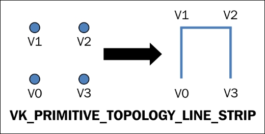
VK_PRIMITIVE_TOPOLOGY_LINE_STRIP = 2,
VK_PRIMITIVE_TOPOLOGY_TRIANGLE_LIST = 3,
VK_PRIMITIVE_TOPOLOGY_TRIANGLE_STRIP = 4,
VK_PRIMITIVE_TOPOLOGY_TRIANGLE_FAN = 5,
VK_PRIMITIVE_TOPOLOGY_LINE_LIST_WITH_ADJACENCY = 6,
VK_PRIMITIVE_TOPOLOGY_LINE_STRIP_WITH_ADJACENCY = 7,
VK_PRIMITIVE_TOPOLOGY_TRIANGLE_LIST_WITH_ADJACENCY = 8,
VK_PRIMITIVE_TOPOLOGY_TRIANGLE_STRIP_WITH_ADJACENCY = 9,
VK_PRIMITIVE_TOPOLOGY_PATCH_LIST = 10,
} VkPrimitiveTopology;
Primitive topologies can be divided into two types: adjacency and non-adjacency. In the former type, special mathematical rules are used to identify adjacent vertices in a set of vertices that are used for drawing primitives. The adjacent vertices are accessible in the geometric shaders. On the other hand, the latter type does not have the concept of adjacency vertices.
Let's take a quick look at each of these primitives in the following table:
|
Primitive topology types |
Description |
|
|
Each incoming vertex position represents a point primitive. For this, the provoking vertex index is i.

|
|
|
Each pair of vertices is used to render a line between them. For this, the provoking vertex index is 2i.

|
|
|
Each vertex makes a line between itself and the vertex that precedes it. For this, the provoking vertex index is i.
|
|
|
A set of three vertices is used to form a filled triangle. For this, the provoking vertex index is 3i.

|
|
|
Every vertex makes a triangle with the preceding two vertices. For this, the provoking vertex index is i.

|
|
|
Every vertex makes a triangle with the first vertex and the vertex that precedes it. This generates a fan-like pattern. For this, the provoking vertex index is i+1.

|
In this section, we will understand line and triangle primitives with the adjacency rule:
VK_PRIMITIVE_TOPOLOGY_LINE_LIST_WITH_ADJACENCY: This enum type defines a line list with adjacency. Here, for a givenNnumber of vertices, each of the 4i+1st and 4i+2nd vertices is used to draw a line segment. The 4i+0th and 4i+3rd vertices are considered as adjacency vertices of the 4i+1st and 4i+2nd vertices, respectively; here, i ranges from 0 to N-1. If the geometry shader stage is active, then these adjacency vertices are accessible in the geometry shader; if not, they are ignored:

VK_PRIMITIVE_TOPOLOGY_LINE_STRIP_WITH_ADJACENCY: This type of line enum defines a line strip with adjacency. For a given N+3 vertices, each of the i+1st to i+2nd vertices are used to draw a line segment. The number of vertices must be more than four; otherwise, the drawing is ignored. For each line segment i, the i+0th and i+3rd vertices are considered the adjacency vertices of the i+1st and 4i+2nd vertices, respectively.

VK_PRIMITIVE_TOPOLOGY_TRIANGLE_LIST_WITH_ADJACENCY: This enum type defines the triangle list with the adjacency. Here, for a given 6n+k vertices, the 6ith, 6i+2nd, and 6i+4th vertices resolve into a triangle (refer to the following diagram: 0, 2 and 4), where i ranges from 0, 1, 2,... to n-1, and k could be either 0, 1, 2, 3, 4, or 5. If k is not zero, then the last k vertices are ignored.
For each determined triangle, the i, 6i+1st, 6i+3rd, and 6i+5st vertices (refer to the following diagram: 0, 1, 3 and 5) have their adjacent edges produced by the pair of vertices 6i and 6i+2nd, 6i+2nd and 6i+4th, and 6i+4th and 6ith. In the diagram, these adjacent edges are represented by 0 to 2, 2 to 4, and 4 to 6. If the geometry shader stage is active, then the adjacent vertices of each triangle are accessible in a geometry shader; if not, they will be ignored.

VK_PRIMITIVE_TOPOLOGY_TRIANGLE_STRIP_WITH_ADJACENCY: This is another type of adjacency triangle enum. For a given 2(n+2)+k vertices, there are n triangles drawn such that k can take either 0 or 1. The final vertex is ignored if k is equal to 1. If the geometry shader stage is active, then the adjacent vertices of each triangle are accessible in a geometry shader; if not, they are ignored.
The following rule table describes the triangle strip with the adjacency vertices' drawing order for each triangle:

The following diagram shows the rendering of the primitive under the triangle strip with the adjacency rule:

In this next section, we will turn primitives into fragments using rasterization.
Fragments are produced using primitive topologies in the rasterization stage. A rasterized image consists of tiny squares called fragments, arranged in grid fashion. Fragments are a logical combination of the (x, y) position in the framebuffer, corresponding to a depth (z) along with the related data and attributes added by the fragment shaders.
Each primitive goes through the rasterization process and the corresponding fragments are determined according to the topology shape. In this, each primitive's integer position is computed, resulting in the corresponding point or square on the framebuffer grid. Along with the position, one or more depth values with their attributes, which are responsible for determining the final fragment color, are stored in the framebuffer. There can be one or more depth values for each computed point; this indicates that there are multiple overlapped primitives (fully or partially) contending for the same position. These fragments are then resolved based on the depth and associated attributes.
The fragments could be non-square, and this does not affect how the rasterization process works. Rasterization is independent of the aspect ratio of the fragments. The fragments are assumed to be squares since a square simplifies antialiasing and texturing.
The final computed fragment is a pixel that corresponds to the framebuffer. Any fragment that belongs outside the framebuffer dimension is discarded and never considered in the later stages of the pipeline, including any of the early per-fragment tests. The fragment shader processes the surviving fragments and modifies the existing depth value and the associated data with the fragments.
Rasterization is managed through the rasterization state, which can be programmatically controlled using the VkPipelineRasterizationStateCreateInfo structure. This structure provides vital information associated with the rasterization stage—such as the polygon fill mode, front facing, and culling mode—and checks whether the depth is enabled in the rasterization process. It also checks whether the discarded fragments are enabled. Here is the syntax information:
typedef struct VkPipelineRasterizationStateCreateInfo {
    VkStructureType                          pType;
    const void*                              pNext;
    VkPipelineRasterizationStateCreateFlags  flags;
    VkBool32                                 depthClampEnable;
    VkBool32                                 rasterizerDiscardEnable;
    VkPolygonMode                            polygonMode;
    VkCullModeFlags                          cullMode;
    VkFrontFace                              frontFace;
    VkBool32                                 depthBiasEnable;
    float                                    depthBiasConstantFactor;
    float                                    depthBiasClamp;
    float                                    depthBiasSlopeFactor;
    float                                    lineWidth;
} VkPipelineRasterizationStateCreateInfo;
The following table describes each of the parameters of this structure:
|
Parameters |
Description |
|
|
This is the type information of this control structure. It must be specified as |
|
|
This could be a valid pointer to an extension-specific structure or |
|
|
This field is reserved for future implementation. |
|
|
This Boolean flag controls whether the fragment's depth values are clamped with the z planes of the frustum instead of the clipping primitives. |
|
|
Before the rasterization stage is reached, this flag value can be used to control whether the corresponding primitives are to be discarded. |
|
|
The triangle primitive can be rendered in various modes, such as point, filled, or outline. This mode is represented by the |
|
|
This indicates the culling mode for primitives using
enum values that specify no culling, front triangle face culling, back triangle face culling, and both front and back face culling, respectively.
|
|
|
This indicates that the direction of the triangle vertices' orientation is to be considered as front-facing using the |
|
|
The bias fragment's depth values can be controlled using this field. |
|
|
For each fragment's depth value, a constant depth can be added using this scalar factor. |
|
|
This field is a scalar factor that is used to represent the highest or lowest depth bias of a fragment. |
|
|
This field is a scalar factor that applies to the depth bias calculation on the fragment's slope. |
|
|
This is the scalar value that controls the rasterized line segments width. |
In this section, we will implement the rasterization state inside the VulkanPipeline:: createPipeline() function. Rasterization produces the fragments associated with the primitives involved in this stage. The following implementation specifies that the primitives need to be render-filled. It culls out the back faces where the front face is determined by the front-facing rule, which considers the vertices to be ordered in a clockwise direction:
    /********** VulkanPipeline.cpp **********/

    // Inside VulkanPipeline::createPipeline()
    VkPipelineRasterizationStateCreateInfo rasterStateInfo = {};
    rasterStateInfo.sType   =
    VK_STRUCTURE_TYPE_PIPELINE_RASTERIZATION_STATE_CREATE_INFO;
    rasterStateInfo.pNext              = NULL;
    rasterStateInfo.flags              = 0;
    rasterStateInfo.polygonMode        = VK_POLYGON_MODE_FILL;
    rasterStateInfo.cullMode           = VK_CULL_MODE_BACK_BIT;
    rasterStateInfo.frontFace    = VK_FRONT_FACE_CLOCKWISE;
    rasterStateInfo.depthClampEnable         = includeDepth;
    rasterStateInfo.rasterizerDiscardEnable  = VK_FALSE;
    rasterStateInfo.depthBiasEnable          = VK_FALSE;
    rasterStateInfo.depthBiasConstantFactor  = 0;
    rasterStateInfo.depthBiasClamp           = 0;
    rasterStateInfo.depthBiasSlopeFactor     = 0;
    rasterStateInfo.lineWidth                = 1.0f;
In the next section, we will look at the color-blending state in the Vulkan API and its implementation.
Blending is a process in which a source fragment is merged into a destination fragment with some special rules that are determined by the blending factors. Both the source and destination fragment consist of four components; among these, three correspond to the color components (R, G, B) and one to the alpha component that controls opacity.
For each given sample location in the framebuffer, the incoming source fragment (Rs, Gs, Bs, As) are merged into the destination fragment (Rd, Gd, Bd, Ad) and stored in the fragment location (x, y) in the framebuffer.
The blending computations are performed with higher precession; they are always carried out on the floating point basis, where the precession is not lower than the destination components. Therefore, any signed and unsigned normalized fixed point is converted into a floating point first to achieve the highest precession possible.
Blending is controlled by the blending operation, blending factor, and blend constants:
- Blending operations: These define the basic math equations that are used to combine the source and destination values, for example, addition (
VK_BLEND_OP_ADD), subtraction (VK_BLEND_OP_SUBTRACT), and reverse subtraction (VK_BLEND_OP_REVERSE_SUBTRACT). - Blending factors: The weighting of each component is determined by the blending factors. These factors can be used to modify the blending operation used.
- Blending constants: This is a constant color component (R, G, B, A) that is used for blending and produces a new set of color components.
Inside the graphics pipeline, the blend state is specified using the VkPipeline-ColorBlendStateCreateInfo control structure:
typedef struct VkPipelineColorBlendStateCreateInfo {
    VkStructureType                               sType;
    const void*                                   pNext;
    VkPipelineColorBlendStateCreateFlags          flags;
    VkBool32                                      logicOpEnable;
    VkLogicOp                                     logicOp;
    uint32_t                                      pAttachmentCount;
    const VkPipelineColorBlendAttachmentState*    attachments;
    float                                         blendConstants[4];
} VkPipelineColorBlendStateCreateInfo;
The following table describes the various fields of this structure:
|
Parameters |
Description |
|
|
This is the type information of this control structure. It must be specified as |
|
|
This could be a valid pointer to an extension-specific structure or |
|
|
This field is reserved for future use. |
|
|
This is a Boolean flag to determine whether to apply logical operations or not. |
|
|
If |
|
|
This indicates the total number of object elements in |
|
|
This is an array of elements (of the type |
|
|
Based on the blend factors used, this indicates the four color values (R, G, B, A) used in the blending. |
The VkPipelineColorBlendStateCreateInfo control structure takes VkPipelineColorBlendAttachmentState as an input. It specifies the blend factor and blend operation for each color attachment in the number of subpasses used in the present pipeline. Here is the syntax of this:
typedef struct VkPipelineColorBlendAttachmentState {
    VkBool32                 blendEnable;
    VkBlendFactor            srcColorBlendFactor;
    VkBlendFactor            dstColorBlendFactor;
    VkBlendOp                colorBlendOp;
    VkBlendFactor            srcAlphaBlendFactor;
    VkBlendFactor            dstAlphaBlendFactor;
    VkBlendOp                alphaBlendOp;
    VkColorComponentFlags    colorWriteMask;
} VkPipelineColorBlendAttachmentState;
The various fields of VkPipelineColorBlendAttachmentState are as follows:
|
Parameters |
Description |
|
|
This indicates whether blending is enabled for the corresponding color attachment. The source fragment's color remains unmodified when blending is disabled. |
|
|
This field specifies the blend factor that is applied to calculate the source factors (Sr, Sg, Sb). |
|
|
This field specifies the blend factor that is applied to calculate the destination factors (Dr, Dg, Db). |
|
|
This indicates which blend factor to apply on the source's and destination's color to calculate and write the final color value (RGB) into the color attachment. |
|
|
This field specifies the blend factor that is applied to calculate the source's alpha channel, namely Sa. |
|
|
This field specifies the blend factor that is applied to calculate the destination's alpha channel, namely Da. |
|
|
This field specifies which blend factor is applied on the source's and destination's alpha channel to compute and write the final alpha value (A) into the color attachment. |
|
|
This field specifies the color channel's (R, G, B, A) bitmask value that is used to write into the color attachment buffer. |
The process of color blending is implemented in the VulkanPipeline::createPipeline() function. This function defines the blending attributes for the color attachment with the VkPipelineColorBlendAttachmentState structure object (colorBlendAttachmentStateInfo). This structure determines whether the color blending is enabled or disabled. If enabled, then various properties, such as alpha and color blending operations, are specified. There are multiple blend operation (VkBlendOp) equations that can be used to merge the two, such as adding, subtracting, reverse subtracting, and so on. In addition, for both the source and destination fragments, color and alpha blend factors are initialized here.
Next, create the VkPipelineColorBlendStateCreateInfo object's colorBlendStateInfo and pass colorBlendAttachmentStateInfo into it. This structure specifies the color attachments that will be treated using color blending state information. In addition, the logical blending operation is also initialized using logicOp (of the type VkLogicOp). The other important piece of information specified is the color blend constant. Refer to the following code implementation:
    /********** VulkanPipeline.cpp **********/

    // Inside VulkanPipeline::createPipeline()

    // Create the color blend attachment information
    VkPipelineColorBlendAttachmentState
               colorBlendAttachmentStateInfo[1] = {};
    colorBlendAttachmentStateInfo[0].colorWriteMask = 0xf;
    colorBlendAttachmentStateInfo[0].blendEnable   = VK_FALSE;

    // Define color and alpha blending operation.
    colorBlendAttachmentStateInfo[0].alphaBlendOp  = VK_BLEND_OP_ADD;
    colorBlendAttachmentStateInfo[0].colorBlendOp  = VK_BLEND_OP_ADD;

    // Set the source and destination color/alpha blend factors
    colorBlendAttachmentStateInfo[0].srcColorBlendFactor =
                                 VK_BLEND_FACTOR_ZERO;
    colorBlendAttachmentStateInfo[0].dstColorBlendFactor =
                                 VK_BLEND_FACTOR_ZERO;
    colorBlendAttachmentStateInfo[0].srcAlphaBlendFactor =
                                 VK_BLEND_FACTOR_ZERO;
    colorBlendAttachmentStateInfo[0].dstAlphaBlendFactor =
                                 VK_BLEND_FACTOR_ZERO;

    VkPipelineColorBlendStateCreateInfo colorBlendStateInfo = {};
    colorBlendStateInfo.sType                = VK_STRUCTURE_TYPE-
                          _PIPELINE_COLOR_BLEND_STATE_CREATE_INFO;
    colorBlendStateInfo.flags                = 0;
    colorBlendStateInfo.pNext                = NULL;
    colorBlendStateInfo.attachmentCount      = 1;
    // Specify the color blend attachment state object
    colorBlendStateInfo.pAttachments = colorBlendAttachmentStateInfo;
    colorBlendStateInfo.logicOpEnable  = VK_FALSE;
    colorBlendStateInfo.blendConstants[0]    = 1.0f;
    colorBlendStateInfo.blendConstants[1]    = 1.0f;
    colorBlendStateInfo.blendConstants[2]    = 1.0f;
    colorBlendStateInfo.blendConstants[3]    = 1.0f;
Now we move on to pipeline states. We start with discussing viewport management.
A viewport is a portion of the surface region on which the rendering of the primitives will be performed. It defines the physical dimensions in pixels using the VkViewport structure, which states a 2D presentation region and the depth range. These two are combined and then used to perform the viewport transformation.
Now for a bit about viewport transformation. During the viewport transformation process, the normalized device coordinates are converted into framebuffer coordinates using the viewport's 2D region and depth range defined in VkViewport.
The viewport transformation process is part of the graphics pipeline and is controlled using the VkPipelineViewportStateCreateInfo control structure. This structure not only defines the viewports, but the scissors as well.
Using this structure, more than one viewport can be specified; the maximum number of viewports can be determined using VkPhysicalDeviceLimits::maxViewports minus one. The following is the syntax for this:
typedef struct VkPipelineViewportStateCreateInfo {
    VkStructureType                       sType;
    const void*                           pNext;
    VkPipelineViewportStateCreateFlags    flags;
    uint32_t                              viewportCount;
    const VkViewport*                     pViewports;
    uint32_t                              scissorCount;
    const VkRect2D*                       pScissors;
} VkPipelineViewportStateCreateInfo;
Let's look at the various fields of this structure:
|
Parameters |
Description |
|
|
This is the type information of this control structure. It must be specified as |
|
|
This could be a valid pointer to an extension-specific structure or |
|
|
This field is reserved for future implementation and must be specified as |
|
|
This indicates the total number of viewports in the |
|
|
This is a pointer to an array of viewports (of the type |
|
|
This indicates the number of scissors used in the pipeline. This must be equal to the number of viewports specified by |
|
|
This is a pointer to an array of rectangular bounding regions for each corresponding viewport specified by the |
In the following subsection, we will implement the viewport's state object.
The following is the viewport implementation in the VulkanPipeline::createPipeline() function. First, create the VkPipelineViewportStateCreateInfo object and assign the number of viewports and scissors used by this pipeline. In the beginning of this section, we declared that the viewport state is a dynamic state. This indicates to the pipeline that the viewport parameters are subject to changes and will be set using vkSetCmdViewport() in the initViewport() function. Therefore, the pViewports and pScissors parameters are NULL by default:
     /********** VulkanPipeline.cpp **********/

    // Inside VulkanPipeline::createPipeline()


    // Define the number of viewport, this must be equal to number

    // of scissors should be equal.
    #define NUMBER_OF_VIEWPORTS 1
    #define NUMBER_OF_SCISSORS NUMBER_OF_VIEWPORTS

    // Create the viewport state create info and provide the

    // the number of viewport and scissors being used in the

    // rendering pipeline.
    VkPipelineViewportStateCreateInfo viewportStateInfo = {};
    viewportStateInfo.sType            = VK_STRUCTURE_TYPE_-
                                         PIPELINE_VIEWPORT_STATE_
                                         CREATE_INFO;
    viewportStateInfo.pNext            = NULL;
    viewportStateInfo.flags            = 0;

    // Number of viewports must be equal to number of scissors.
    viewportStateInfo.viewportCount    = NUMBER_OF_VIEWPORTS;
    viewportStateInfo.scissorCount     = NUMBER_OF_SCISSORS;
    viewportStateInfo.pScissors        = NULL;
    viewportStateInfo.pViewports       = NULL;
A depth test is a stored fragment that may contain different depth values belonging to each of the overlapped primitives on the same framebuffer location. These values are compared and stored in the depth buffer attachment. This is done to conditionally clip out the fragments based on the value stored in the depth buffer attachment; for a given fragment, the value is generally stored at the location (xf, yf) in the framebuffer.
A stencil test makes use of the depth/stencil attachment and compares the value stored at the framebuffer location (xf, yf) with a given reference value. Depending upon the stencil test state, the stencil value and the stencil write masks are updated in the stencil/depth attachments.
The depth and stencil states are controlled using the VkPipelineDepthStencil-StateCreateInfo structure. Depth and stencil tests can be enabled or disabled using the member variables depthBoundsTestEnable and stencilTestEnable.
The following is the syntax and description of VkPipelineDepthStencilState-CreateInfo:
typedef struct VkPipelineDepthStencilStateCreateInfo {
    VkStructureType                         SType;
    const void*                             pNext;
    VkPipelineDepthStencilStateCreateFlags  flags;
    VkBool32                                depthTestEnable;
    VkBool32                                depthWriteEnable;
    VkCompareOp                             depthCompareOp;
    VkBool32                                depthBoundsTestEnable;
    VkBool32                                stencilTestEnable;
    VkStencilOpState                        front;
    VkStencilOpState                        back;
    float                                   minDepthBounds;
    float                                   maxDepthBounds;
} VkPipelineDepthStencilStateCreateInfo;
Let's look at the various fields of this structure:
|
Parameters |
Description |
|
|
This is the type information of this control structure. It must be specified as |
|
|
This could be a valid pointer to an extension-specific structure or |
|
|
This field is reserved for future implementation and must be specified as |
|
|
This is the Boolean flag to check whether the depth test is enabled. |
|
|
This field checks whether the depth writes are enabled. |
|
|
This field is the comparison operator that will be used in the depth test. |
|
|
This is the Boolean flag that checks whether the depth bound test is enabled or disabled. |
|
|
This checks whether the stencil test is enabled or disabled. |
|
|
This is the parameter that corresponds to the front control of the stencil test. |
|
|
This is the parameter that corresponds to the back control of the stencil test. |
|
|
This is the minimum range of values used in the depth bounds test. |
|
|
This is the maximum range of values used in the depth bounds test. |
At the beginning of this function (createPipeline()), we defined some dynamic states (VkDynamicState) that indicate to the pipeline which states will be controlled dynamically in the pipeline. If the depth state (VK_DYNAMIC_STATE_DEPTH_BOUNDS) is not defined dynamically, then the depth bounds test is defined by the minDepthBounds and maxDepthBounds members of VkPipelineDepthStencilStateCreateInfo.
On the other hand, if the dynamic depth bound test is enabled, then the depth bound range can be set at runtime using the vkCmdSetDepthBounds API. This API takes three parameters. The first parameter is the command buffer, and the next two parameters specify the minimum and maximum depth bounding values. Here's the syntax of this API:
void vkCmdSetDepthBounds(
   VkCommandBuffer         commandBuffer,
   float                   minDepthBounds,
   float                   maxDepthBounds);
The next state defined in createPipeline() is the depth/stencil state. In the following code, VkPipelineDepthStencilStateCreateInfo is created, and it determines whether the depth and stencil tests are enabled using the includeDepth boolean flag. In the present case, the depth test is enabled; therefore, we should provide more information to the pipeline specify how to carry out the depth and stencil operation. This information may include a depth comparison operation, which tells how the depth buffer values are compared to the incoming depth values to update the depth buffer when the depth write is enabled. Similarly, some of the other fields that are defined are compare masks and the minimum and maximum depth bound ranges. Refer to the implementation in the following code:
    /********** VulkanPipeline.cpp **********/

    // Inside VulkanPipeline::createPipeline()
    VkPipelineDepthStencilStateCreateInfo depthStencilStateInfo = {};
    depthStencilStateInfo.sType              = VK_STRUCTURE_TYPE_PIPELINE-
    _DEPTH_STENCIL_STATE_CREATE_INFO;
    depthStencilStateInfo.pNext              = NULL;
    depthStencilStateInfo.flags              = 0;
    depthStencilStateInfo.depthTestEnable    = includeDepth;
    depthStencilStateInfo.depthWriteEnable   = includeDepth;
    depthStencilStateInfo.depthCompareOp     = VK_COMPARE_OP_LESS
    _OR_EQUAL;
    depthStencilStateInfo.depthBoundsTestEnable    = VK_FALSE;
    depthStencilStateInfo.stencilTestEnable        = VK_FALSE;
    depthStencilStateInfo.back.failOp  = VK_STENCIL_OP_KEEP;
    depthStencilStateInfo.back.passOp  = VK_STENCIL_OP_KEEP;
    depthStencilStateInfo.back.compareOp     = VK_COMPARE_OP_ALWAYS;
    depthStencilStateInfo.back.compareMask   = 0;
    depthStencilStateInfo.back.reference     = 0;
    depthStencilStateInfo.back.depthFailOp   = VK_STENCIL_OP_KEEP;
    depthStencilStateInfo.back.writeMask     = 0;
    depthStencilStateInfo.minDepthBounds     = 0;
    depthStencilStateInfo.maxDepthBounds     = 0;
    depthStencilStateInfo.stencilTestEnable = VK_FALSE;
    depthStencilStateInfo.front        = depthStencilStateInfo.back;
In the next section, we will look at the multisampling state, which controls the appearance of rastered images in order to improve the quality of the presentation.
Multisampling is a mechanism that removes the aliasing effects produced during the Vulkan primitive rasterization. The antialiasing takes multiple samples from the geometry for a given pixel to generate a smooth approximation such that it minimizes the stair-step case effect and makes the edges appear smooth.
Antialiasing is a technique in computer graphics that improves the quality of the rendered image or video output displayed on the screen by minimizing jagged lines or the stair-step case effect. The raster framebuffer is composed of hundreds of tiny square pixels arranged in a grid format. During image rasterization, the geometry is sampled for a given pixel using a sampling scheme, which will be discussed later in this section. Basically, the cause of antialiasing is point sampling. These samples are represented by rectangular pixels, which are not sufficient to produce curved shapes. Edges in the image, which are round (not horizontal or vertical), are responsible for this stair-step case effect, as they end up coloring the pixels as in a stair arrangement. The aliasing problem is not much noticeable when an image or scene is still, but as soon as they are in motion, jagged edges are highly visible.
Once the primitives (points, lines, and triangles) are baked into the final presentation pixels, they are treated with the multisampling process. This allows you to make the Vulkan primitive antialiased by making the edges appear smoother, not jagged. This efficient technique saves a tremendous amount of computation cost )among many other antialiasing techniques). It is the number-one choice of GPU hardware vendors. A multisample takes more than one sample in the computation process for a given pixel in a single pass. In multisampling, a given pixel in the primitive is sampled multiple times where each sampling can utilize the color, depth, and/or stencil values independently, which are later resolved into a single combined color.
In line with the Vulkan specification, the rasterization rules for single-sample modes in Vulkan have been defined in such a way that they are equivalent to a multisample mode with a single sample in the center of each pixel.
Multisampling can be organized within the pipeline using the VkPipeline-MultisampleStateCreateInfo structure. Refer to the following subsection to understand the API specification and its implementation. First, let's look at the syntax of this structure:
typedef struct VkPipelineMultisampleStateCreateInfo {
    VkStructureType                          sType;
    const void*                              pNext;
    VkPipelineMultisampleStateCreateFlags    flags;
    VkSampleCountFlagBits                    rasterizationSamples;
    VkBool32                                 sampleShadingEnable;
    float                                    minSampleShading;
    const VkSampleMask*                      pSampleMask;
    VkBool32                                 alphaToCoverageEnable;
    VkBool32                                 alphaToOneEnable;
} VkPipelineMultisampleStateCreateInfo;
Let's look at the various fields of this structure:
|
Parameters |
Description |
|
|
This is the type information of this control structure. It must be specified as |
|
|
This could be a valid pointer to an extension-specific structure or |
|
|
This field is |
|
|
This field indicates the number of samples used per pixel in the rasterization. |
|
|
The Boolean flags indicate whether the fragment shading will be executed according to a per-sample or per-fragment basis. If the value is |
|
|
This specifies the minimum number of unique samples required to shade for each fragment. |
|
|
This field is the bitmask that is used for ANDing the static coverage information with the rasterization-generated coverage information. |
|
|
This field controls whether the value of the alpha component of the fragment's first color output can be used to generate a temporary coverage value. |
|
|
This controls whether the multisampling coverage can replace the alpha component value of the fragment's first color output. |
The last state defined in the VulkanPipeline::createPipeline() function is the multisampling state. First, define the VkPipelineMultisampleStateCreateInfo structure with the correct type information to help the underlying implementation understand the kind of object that is passed in. The sType must be specified as VK_STRUCTURE_TYPE_PIPELINE_MULTISAMPLE_STATE_CREATE_INFO. Next, indicate the number of samples used as coverage values per pixel in rasterizationSample, which is VK_SAMPLE_COUNT_1_BIT in the present case.
Various pixel sampling schemes exists. When the standardSampleLocations member of
VkPhysicalDeviceFeatures
is VK_TRUE, then the sample counts are defined using the samples shown in the following screenshot:

There could be different sample schemes based on the number of samples in a given pixel, which could vary from 1 to 64 samplings. Samplings contain various positions that contribute weights based on a position relative to an origin in the upper left corner of the pixel. When rasterizationSamples is VK_SAMPLE_COUNT_1_BIT, sampling uses the pixel center:
    /************ VulkanPipeline.cpp *************/

    // Inside VulkanPipeline::createPipeline()
    VkPipelineMultisampleStateCreateInfo   multiSampleStateInfo = {};
    multiSampleStateInfo.sType   =
         VK_STRUCTURE_TYPE_PIPELINE_MULTISAMPLE_STATE_CREATE_INFO;
    multiSampleStateInfo.pNext                     = NULL;
    multiSampleStateInfo.flags                     = 0;
    multiSampleStateInfo.rasterizationSamples      = NUM_SAMPLES;
So far, in the Creating a graphics pipeline section and the Pipeline state objects in Vulkan section, we learned how to create a graphics pipeline and specify various pipeline state objects into it. In the next section, we will understand the execution model of creating the pipeline in our sample application.