
Chapter 1: Introduction to Microcontrollers and Microcontroller Boards
In this chapter, you will learn how to set up fundamental software tools for programming microcontrollers, as well as how to use basic electronic components as a starting point for programming examples for beginners. We will begin with a general introduction to microcontrollers and their definitions, as well as their importance and applications in our everyday lives. We will then go on to give a simplified explanation of the digital and analog electronics necessary for the microcontroller projects carried out in the rest of the chapters. Here, we will also explain the basic equipment that may be used in this book's projects. Finally, we will look at a concise description of the Blue Pill and Curiosity Nano microcontroller boards to be used throughout this book.
Specifically, we will cover the following main topics:
- Introduction to microcontrollers
- An overview of analog and digital electronics necessary for carrying out the book's projects
- Description of the Blue Pill and Curiosity Nano microcontroller boards
We will also cover how to install the necessary software drivers and the integrated development environments (IDEs) for programming the Blue Pill and Curiosity Nano. After completing this introductory chapter, you will be able to apply what you have learned regarding the installation of integrated development environments (a type of software tool) to programming the obligatory Hello World programs used to make an LED blink. This will run on the Blue Pill and Curiosity Nano using C. Don't worry if you don't know a lot about C programming yet; we have you covered; Chapter 2, Software Setup and C Programming for Microcontroller Boards, includes a gentle but concise C programming tutorial.
Technical requirements
The two microcontroller boards described in this book (Blue Pill and Curiosity Nano) can be programmed using different IDEs. An IDE is a programming and debugging software tool that includes a code editor, a compiling environment, debugging options, and so on. Many of the IDEs are also used to upload your compiled program to a microcontroller board via a USB port connection.
These are the IDEs that you will need to install on your computer:
- Arduino IDE: This free IDE was originally created for programming Arduino microcontroller boards, but you can also use it for programming the Blue Pill microcontroller board if you install a library for it.
- MPLAB ® X IDE: Made by Microchip, the Curiosity Nano manufacturer. This is a free IDE necessary for programming the Curiosity Nano.
We will explain how to install and use those IDEs in this chapter.
The code used in this chapter can be found at the book's GitHub repository here:
https://github.com/PacktPublishing/DIY-Microcontroller-Projects-for-Hobbyists/tree/master/Chapter01
The Code in Action video for this chapter can be found here: https://bit.ly/3zSOg8O
For hardware, you will need the following materials:
- A regular LED light – any color will do.
- A 220-ohm resistor; 0.25 watts.
- A solderless breadboard for connecting an LED and a resistor and some male-to-male jumper wires to make the electrical connections between the components and the microcontroller boards.
- A micro USB cable for connecting your microcontroller boards to a computer.
- The Blue Pill and Curiosity Nano boards, of course! There are several vendors and manufacturers of the Blue Pill board, which uses the STM32F103C8T6 microcontroller. In the case of the Curiosity Nano, we use a version called the PIC16F15376 Curiosity Nano PIC® MCU 8-Bit Embedded Evaluation Board, part number DM164148, manufactured by Microchip.
- A programming adapter such as the ST-Link/V2 is also needed. This electronic interface will allow you to upload the compiled code to the Blue Pill, establishing communication from your computer to the Blue Pill microcontroller board. The ST-Link/V2 needs four female-to-female DuPont wires.
Some of the sensors used in this book can be found in a sensor kit in the form of practical modules, such as the Kumantech 37-in-1 sensor kit:
This kit can be used with many types of microcontroller boards, including the Blue Pill and the Curiosity Nano. Sometimes, it is convenient to buy a sensor kit like this one for experimenting with its sensor modules. Some other kits include components such as resistors and code examples.
Introduction to microcontrollers
In this section, we will focus on what a microcontroller is and what its main parts are. It is important to understand what the microcontrollers are capable of and how they are used as a fundamental part of many embedded systems, so they can be used in real-world projects. An embedded system is a computer subsystem that usually works as part of a larger computer system, for example, a wireless router containing a microcontroller. Let's start with a definition of microcontrollers.
A microcontroller (also known as a microcontroller unit, or MCU) is a very small computer system self-contained in an integrated circuit (IC). It encases all the necessary computing components to execute tasks, computes numeric calculations, reads data from sensors, keeps data and a program in memory, and send data to actuators, among other actions. Most of the microcontrollers perform analog-to-digital conversion (ADC), obtaining analog data from sensors and converting it to digital values. More on ADC is explained in Chapter 4, Measuring the Amount of Light with a Photoresistor. Digital values are defined by binary values (1 or 0). The next section explains more about those values.
Microcontrollers have an internal clock signal that is like a heartbeat that coordinates how tasks and other actions are performed in the microcontroller. This clock signal is not as fast as microprocessors (used by desktop computers and laptops), but it is enough for doing basic operations such as reading a sensor or controlling a motor. Their internal memory is limited, but enough for storing a program capable of running a particular task. In general, microcontrollers do not use an external data storage device such as a hard drive. Everything they need to run is encased in their IC.
An IC is an electronic circuit densely packaged in a small and flat piece of plastic. It contains many microscopic electronic components and electrically connected pins. ICs are manufactured in different packaging. Dual in-line packaging (DIL) houses two rows of electrically connecting pins. Quad flat packaging (QFP) includes 8–70 pins per side, useful for surface mounting soldering. Microcontrollers are encased in ICs, as well as other electronic parts.
The pins of some microcontrollers are organized into two rows using DIL packaging. Other ICs, such as the STM32 microcontroller, have four rows of pins, which is known as QFP.
Microcontrollers are also called a computer in a chip. They generally have low-power consumption, and, of course, are reduced in size. Some of them are smaller than a fingernail! Microcontrollers are generally used to perform a specific task and execute one particular application, such as controlling the internal functions of a coffee maker, one at a time. Microcontrollers are applied in situations where dedicated and limited computer functions are needed.
Microcontroller boards
A microcontroller board is an electronic circuit containing a microcontroller and other supporting components such as voltage dividers/shifters, a USB interface, connection pins, resistors, capacitors, and an external clock.
The purpose of microcontroller boards is to facilitate the connection of external devices, sensors, and actuators to microcontrollers, accelerating project prototyping. For example, the Blue Pill microcontroller board contains its microcontroller at its center, and it has some other components supporting its functions.
Microcontroller boards such as the Blue Pill have input/output (I/O) ports, or pins, where sensors, motors, and other electronic components and devices are connected to them. The boards will either read or send data to them through the ports. The boards also have useful pins such as the ground and voltage pins, so sensors and other components can be connected to them to work. Some I/O pins read analog voltages coming from sensors or send analog voltages to actuators (for example, motors), and others are digital pins used for reading and sending digital voltages, typically 0 and 5 volts, or 0 and 3.3 volts. All computers (including microcontrollers) work internally with digital binary numbers containing 0s and 1s. The binary value 0 is represented by 0 volts, and the binary value 1 is represented by either 3.3 or 5 volts. For example, a digital value (1) sent to a digital port could turn on an LED connected to it.
The next section defines what electronics is, and what are analog and digital electronics. These definitions are important in understanding how some electronic components and electronic circuits work, which will be used in this book's chapters.
An overview of analog and digital electronics necessary for carrying out the book's projects
Electronics is the branch of technology and physics concerning the emission and behavior of electrons moving in a conductor, semiconductor, gas, or vacuum. Electronics also deals with the design of electronic circuits and devices. Figure 1.1 shows a diagram of a basic electronic circuit consisting of a power source (the batteries), a resistor, and a light source (a light-emitting diode, or LED):
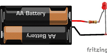
Figure 1.1 – An example of an electronic circuit
The electrons flow from the battery's negative (black) terminal through the circuit passing through the LED illuminating it. Don't worry if you don't understand this circuit and its components yet. We will review these in the next paragraphs, and we will use them in other chapters. Analog electronics are electronic circuits that provide and process continuous variable voltage signals, for example, analog voltages that change from 0 to 3.3 volts. Conversely, digital electronics provide and process discrete voltage signals that represent binary values. For example, 0 volts represents a 0 in binary, and 3.3 volts represents a 1 in binary, and no other voltages are used in between. This is how computers and microcontrollers work internally at the lowest level. Microcontrollers convert analog values to digital values internally in order to process incoming signals and then process them digitally. This is called analog-to-digital conversion (ADC). We will need to understand four key electronics terms that will be covered in other chapters, which are standard units used to measure the flow of electrons:
- Current: Current is the rate of flow of electrons in a circuit. Electrons flow through a conductive material from the negative pole of a power source (such as a battery) to its positive pole. This is known as direct current (DC). The negative side is called ground (GND, or G), sometimes also called earth. Current is measured in amperes or amps, denoted by the letter I or i.
- Voltage: This is an electrical measurement of the difference in potential energy between the positive and negative poles of a power source in an electronic circuit. It is measured in volts (V). It is considered as the pressure from an electrical circuit's power source pushing charged electrons (current) through an electric/electronic circuit.
- Power: Power is a rate measurement of how an electric or electronic circuit or device converts energy from one form to another. Power is measured in watts (W). For example, a 60 W lightbulb is brighter than a 40 W lightbulb because the 60 W lightbulb converts electrical energy into light at a higher rate.
- Resistance: The electrical resistance of an electrical conductor is the measurement of the difficulty of the electrons in passing an electric current through the conductor. It is measured in ohms, denoted by the Greek letter Omega (Ω). Ohm's law describes the conductivity of many electrically conductive materials. It establishes that the current between two points in a conductor is directly proportional to the voltage across the two points, where its resistance is constant. This law can be mathematically described as I=V/R, and it is very useful for calculating either current, voltage, or resistance in an electronic circuit.
In this section, we have covered fundamental standard measurement units used in electronic circuits that you will apply in all the chapters of this book. The next section deals with important electronic components that you will also need to know before starting experimenting with electronic circuits and microcontroller boards.
Basic electronic components
The following are electronic components commonly used in many microcontroller board projects and in most of the projects described in this book. They allow us to control the current in electronic circuits. We will review four main electronic components: the resistor, the diode, the capacitor, and the transistor.
The resistor
Resistors are generally used to reduce the flow of electrons in an electronic circuit. Resistance is useful for allowing some components such as LEDs to work properly in a circuit without burning them. The level of resistance in a resistor can be either fixed or variable. Some resistors can range from one to thousands of ohms (kilo-ohms or kΩ) to millions of ohms (mega-ohms or MΩ). Resistors are also measured by their power rating measured in watts. This refers to how much current they tolerate without overheating and then failing.
Figure 1.2 shows how to read the values of a resistor:
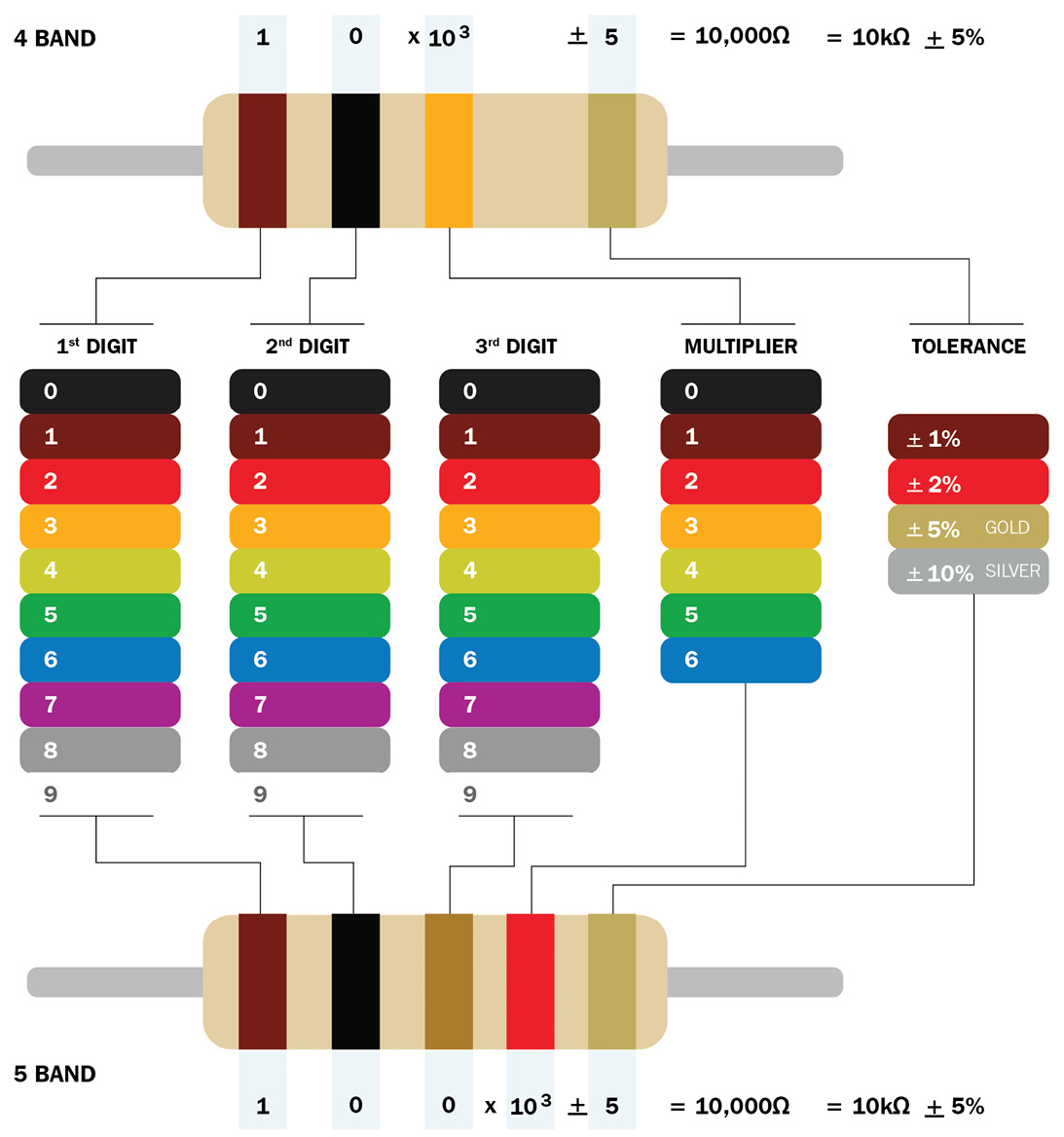
Figure 1.2 – A chart showing how to calculate a resistor value. Image source: "Resistor Color Code", by Adim Kassn, licensed under CC-BY-SA-3.0
Important note
As shown in Figure 1.2, the band colors are:
0: Black
1: Brown
2: Red
3: Orange
4: Yellow
5: Green
6: Blue
7: Violet
8: Silver
9: White
The 1% tolerance band is colored brown, the 2% is colored red, the 5% is colored gold, and the 10% is colored silver. You can access the chart in color via this link: https://commons.wikimedia.org/wiki/File:Resistor_color_code.png.
Common resistors have four color bands (some have five color bands, but this is rarely used in general electronic circuits) determining their ohm values:
- The first band indicates the first digit in its ohm value.
- The second band shows the second digit.
- The third band indicates the third digit (which is typically the number of zeros).
- The fourth band determines the resistor tolerance, which is a degree of resistance precision. For example, if the band is colored silver, this means that the resistor will have a 10% tolerance change according to its marked value.
Many resistors used in microcontroller board projects use ¼ watt resistors, which are enough for simple applications.
The diode
The diode is an electronic component that allows the flow of current in one direction only. Current in a circuit flows into a diode via its anode (+) and flows out through its cathode (-). Diodes are generally used to protect parts of an electronic circuit against reverse current flow. They also help to convert alternate current (AC) to DC, among other applications. Diodes are also used to protect microcontroller boards when we connect motors to them to avoid voltage flyback. This happens when a sudden voltage spike happens across a motor when its supply current is suddenly interrupted or reduced. However, diodes cause a drop in the voltage of around 0.7 V. Diodes are manufactured to handle a certain amount of amperes (current) and voltage. For example, the 1N4004 diode is rated to handle 1 ampere (A) and 400 volts (V), much higher than we will be using in our book's projects. The band around the diode indicates the cathode, generally connected to the ground terminal of a power source. The other pin is the anode, generally connected to the positive (+) terminal of the power source. A common type of diode is the light-emitting diode (LED), which glows when there is a flow of electrons passing through it. They come in different sizes, colors, and shapes. As with regular diodes, LEDs are polarized, so the current enters and leaves the LED in one direction. If too much current passes through the LED, this will damage it. You will need to connect a resistor in series to reduce its current and thus protect it. A resistor with a value of at least 220 ohms should be enough for many microcontroller board applications.
The capacitor
This is an electronic component that temporarily holds (stores) an electric charge. Once the current stops flowing through the capacitor, the charge remains in it and it can be discharged as soon as the capacitor is connected to a circuit. The amount of charge that a capacitor can store is measured in farads (f). Since a farad is a very large amount, many capacitors are made with less than one farad. Capacitors accept certain voltage maximums. 10, 16, 25, and 50 V capacitors are common in microcontroller applications. There are two types: monolithic (they don't have polarity) and electrolytic (they have polarity).
Electrolytic capacitors are bigger than monolithic capacitors, and their polarity is shown as a band on one side marking the cathode pin and another band marking the anode pin. Remember that the cathode pin is connected to the ground terminal of the power source and the anode is connected to the positive voltage terminal of the power source. Typical values of electrolytic capacitors range from 1 microfarad up to 47,000 microfarads. Capacitors can be used in microcontroller board projects for filtering out (cleaning up) digital or analog signals (removing electrical noise), they can convert alternate voltage to direct voltage, and so on. Be very careful when you're using polarized (electrolytic) capacitors! They can hold lots of energy. You should never touch its legs (pins), short circuit, or connect them in reverse. Make sure you connect an electrolytic capacitor in a project by connecting its positive (+) pin to the positive pole of the circuit's power supply (an electronic/electric component that supplies steady power to an electronic circuit or electrical device) and by connecting the capacitor's negative pin to the negative pole of the circuit's power supply. Respect its polarity. If you connect them in reverse (wrong polarity), they will be damaged and can explode. Monolithic (ceramic) capacitors do not have polarity. It doesn't matter how their legs (pins) are connected in the circuit. The typical capacity range of capacitors is from 0.5 picofarads up to 1 microfarad.
The transistor
A transistor can act as a very fast digital switch. Transistors are useful for switching on or off other circuits or devices that require a high current, such as motors and fans. It can also be used as a current amplifier and to form logic gates (AND, OR, NOT, and so on); this current is also called a load. Popular and inexpensive examples are the BC548 and 2N2222 transistors. Transistors are made to hold a certain amount of current and voltage (for example, the BC548 transistor holds a maximum current of 100 mA and 30 V).
Figure 1.3 shows the basic electronic components explained in this section:
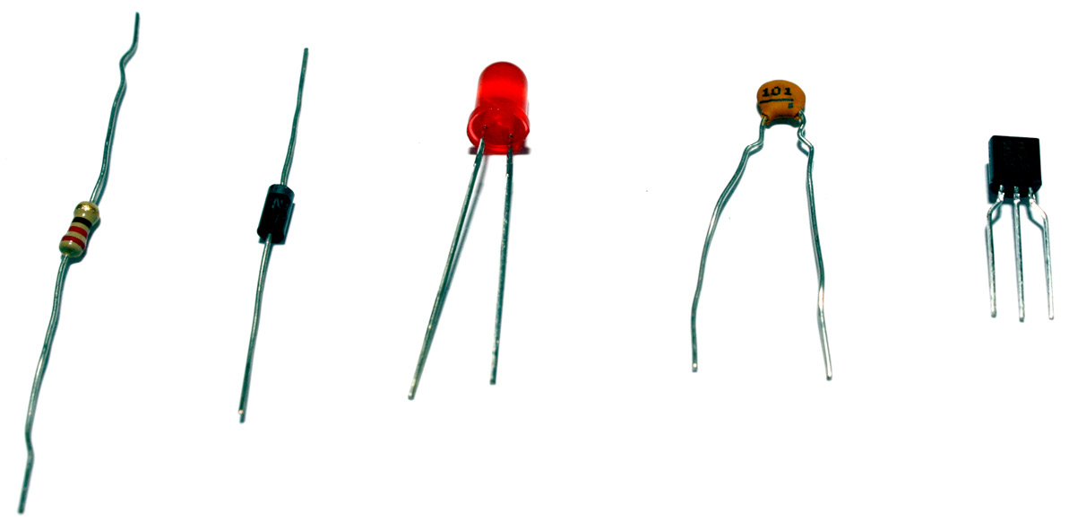
Figure 1.3 – Electronic components (shown from left to right): a resistor, a diode, an LED, a monolithic capacitor, and a transistor
The next section describes a tool called the solderless breadboard, which is very useful for interconnecting electronic components and microcontroller boards.
The solderless breadboard
Another very useful piece that you can use in microcontroller board projects is the solderless breadboard, shown in Figure 1.4. It is used for the rapid prototyping of electronic circuits. Its plastic base has rows of electrically connected sockets, coming in many sizes, shapes, and colors:
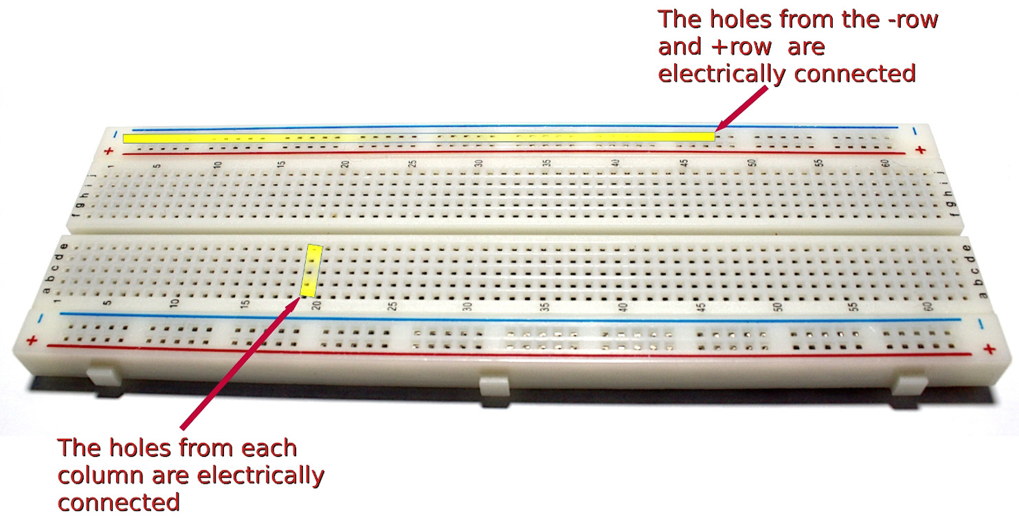
Figure 1.4 – The breadboard's interconnection of columns and rows
Bear in mind that if you insert two wires in one vertical row, then they will be electrically connected. The horizontal rows marked with – and + signs are electrically connected horizontally, as shown in Figure 1.4.
This section described important and useful electronic components such as resistors and LEDs, which are commonly used in electronic projects involving microcontroller boards. The next section describes the Blue Pill and Curiosity Nano microcontroller boards used in this book.
Description of the Blue Pill and Curiosity Nano microcontroller boards
This section explains the Blue Pill and Curiosity Nano microcontroller boards, shown in the following photos. The holes from their upper and lower rows will be connected to the header pin, and most of them are the ports. Figure 1.5 shows the Blue Pill microcontroller board showing the STM32 microcontroller chip at the center:
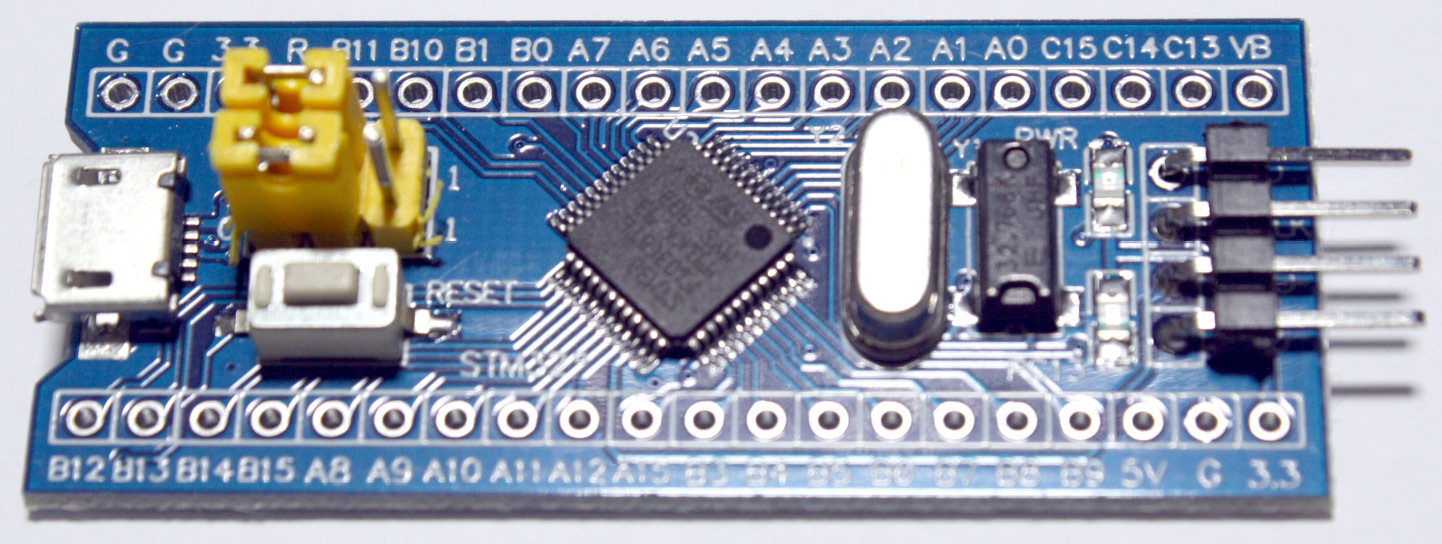
Figure 1.5 – The Blue Pill microcontroller board
Figure 1.6 is a closeup of the Curiosity Nano microcontroller board. Notice its PIC16F15376 microcontroller chip shown at the center:
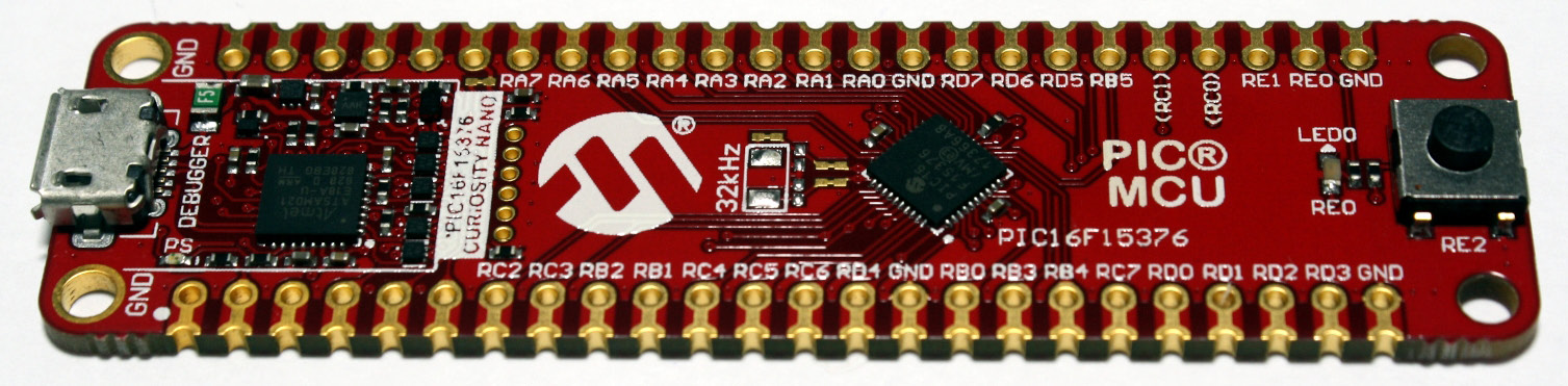
Figure 1.6 – The Curiosity Nano microcontroller board
The black rhombus components at the center of the boards are the microcontrollers. Both boards from the previous photos do not yet have header pins. The reason is that in some projects, it is necessary to solder wires and electronic components directly to a headless board, although in this book you won't need to do that. However, some Curiosity Nano boards allow the pins to be inserted and stay firmly in place without soldering them. In addition, you can buy the Blue Pill with the header pins already soldered. Alternatively, you can solder the header pins to both the Blue Pill and Curiosity Nano boards. Here is a tutorial on how to solder electronics components: https://www.makerspaces.com/how-to-solder/.
Figure 1.7 shows the Blue Pill microcontroller board upside down with the header pins already soldered to it and a separate row of pins:
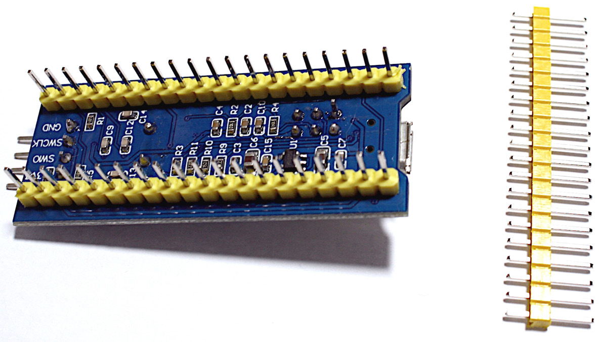
Figure 1.7 – A Blue Pill showing its pins already soldered to it
Once the boards have the header pins in place, you can insert them in solderless breadboards and start prototyping with them without the need for soldering wires or components directly to the boards, which is how we will use them in the projects of this book.
We have selected these microcontroller boards for this book because they are inexpensive, versatile (you can connect different types of sensors, LED lights, motors, and so on, to them), and are reasonably easy to program and use. Microcontroller boards greatly facilitate building prototypes in a short time. You can also apply them in COVID-19- related projects, as we will review this at various points through the book.
In addition, it is always good to learn about boards that use microcontrollers from different families and manufacturers because each one has different capabilities and strengths. The Blue Pill has a microcontroller from the STM32 microcontroller family, and the Curiosity Nano works with a microcontroller from the PIC family.
The Blue Pill has 37 general-purpose I/O pins, including ports PA0 – PA15, PB0 – PB15, and PC13 – PC15. For example, the I/O port PC13 is labeled as C13 on the Blue Pill.
The Curiosity Nano has 35 GPIO ports, including RA0, R1, RA2, RA3, RA4, RA5, RB0, RB3, RB4, RC7, RD0, RD1, RD2, RD3, RC2, RC3, RB2, RB1, RC4, RC5, RC6, and RD4, among others. We will review the programming of those ports in Chapter 2, Software Setup and C Programming for Microcontroller Boards. Table 1.1 shows technical specifications of the two microcontroller boards used in this book:
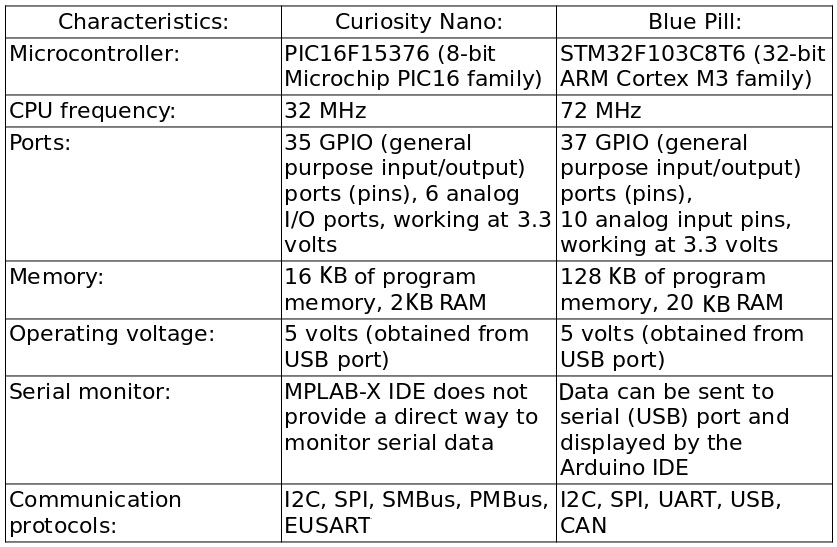
Table 1.1 – Blue Pill and the Curiosity Nano's technical specifications
Both the Blue Pill and the curiosity Nano run at a much higher speed than most of the Arduino microcontrollers. For example, the Arduino Uno microcontroller board runs at 16 MHz.
Installing the IDEs
Next, we will explain the necessary steps to install and use the IDEs for programming the Curiosity Nano and the Blue Pill microcontroller boards.
Installing the MPLAB X IDE for the Curiosity Nano board
The next steps show how to download and install the MPLAB X tool, which is used for programming the Curiosity Nano. This section also explains the main parts of the MPLAB X IDE:
- You should sign in first to the free myMicrochip service (Microchip is the manufacturer of the Curiosity Nano). Fill out the registration form on this web page: https://www.microchip.com/wwwregister/RegisterStep1.aspx.
- Once you're registered, download the MPLAB X IDE from this link: https://www.microchip.com/mplab/mplab-x-ide.
- Go to the Downloads tab and download the IDE according to the operating system that you are using.
- Once you have downloaded the installer, follow these instructions for installing the MPLAB X IDE: https://microchipdeveloper.com/mplabx:installation.
- You will also need to download and install the free XC8 C compiler for programming the Curiosity Nano. Open this link: https://www.microchip.com/mplab/compilers.
- Then, go to the Compiler Downloads tab and download an installer file according to your operating system.
- Download the latest version of the XC8 compiler from there. This version is suitable for programming the PIC16F15376 microcontroller that comes with the Curiosity Nano used in this book. Follow the instructions for installing the XC8 compiler here: https://microchipdeveloper.com/xc8:installation.
It may take some time to download the XC8 compiler, so be patient. The next section describes commonly used components from the MPLAB X IDE.
Understanding the main components of the MPLAB X IDE
This section describes the main parts of the IDE that you will use to edit your program, compile it, and so on.
Figure 1.8 is a screenshot of the MPLAB X IDE:

Figure 1.8 – MPLAB X IDE's main parts
The main parts described in Figure 1.8 include the text editor (code area), which will be used in other chapters of this book. One of the most important buttons in the IDE is the Run button, which compiles, runs, and uploads the binary (compiled) file to the Curiosity Nano board.
Here are the steps for starting a new coding project:
- Click on File/New Project to create a new project.
- Click on the Code tab and start writing your code in the code area.
- Click on the Run icon to compile and upload your code to the microcontroller board. The console will show messages on the process and establish whether everything went to plan.
Unlike other microcontroller boards such as the Blue Pill, you need to configure input and output ports in the Curiosity Nano microcontroller board previous to its use. You do this using a special plugin called the MPLAB X Code Configurator (MCC). You should install the MCC plugin for the MPLAB X IDE. The MCC is a free graphical programming environment that facilitates the configuration of the microcontroller ports, among other applications. It will generate C programming header libraries necessary for reading data from, and writing data to, the microcontroller ports.
This web page explains how to install the MCC in the MPLAB X IDE: https://www.microchip.com/mplab/mplab-code-configurator.
The easiest way to install it is by clicking on Tools/Plugins on the MPLAB X IDE's main menu, and then downloading and installing it from there.
We have now created an MPLAB X project template where we have configured input and output ports for the Curiosity Nano, as well as handling digital and analog data on them. We already used the MCC plugin to set up the I/O ports so you may no longer need to use the MCC plugin for the projects explained in this book and for other projects. It is a convenient template since it has all the necessary libraries for handling the input and output C-programming functions for some of the Curiosity Nano ports. We will review these libraries and the C-programming functions in Chapter 2, Software Setup and C Programming for Microcontroller Boards. The template project is called 16F15376_Curiosity_Nano_IOPorts.zip and is stored on our GitHub's main page.
Just download the zip file, unzip it, and open the project in MPLAB X.
Installing the Arduino IDE and the Blue Pill library
You can use the Arduino IDE for programming the Blue Pill microcontroller board. Perform the following steps to install the Arduino IDE:
- Download the Arduino IDE from its official website for Windows, macOS, or Linux from this site: https://www.arduino.cc/en/main/software. Don't forget to download the correct IDE installer for your operating system.
- Run the installer that you just downloaded and follow the onscreen instructions.
- Identify the Arduino IDE's main options.
Figure 1.9 shows the Arduino IDE and its main parts and areas. The console is a useful component where the IDE shows error or warning messages. The status bar shows the program compilation and uploading status:

Figure 1.9 – Arduino IDE's main parts
Figure 1.9 shows the main parts of the Arduino IDE, including its code editor, status bar, menu bar, and console. One of the most commonly used features is the Upload button, which compiles your program and uploads its compiled code to the Blue Pill. The following steps show how to upload a program to the Blue Pill and how to install a necessary library in the IDE:
- Open an example program by clicking on File/Examples/01.Basics/Blink from the Arduino's menu bar. This will help you to get familiar with the Arduino IDE. A program called Blink will open. Click on the Verify button to compile it and generate the binary file for the microcontroller board. The Upload button will verify, compile, generate the binary file, and then upload the file to the microcontroller board.
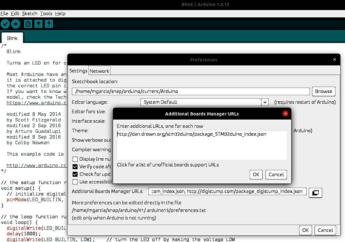
- Before uploading a program to the Blue Pill, you will need to install a library on the Arduino IDE for programming the Blue Pill. To install the Blue Pill library, click on File/Preferences from the IDE's Menu bar. Then, a new window will appear. Click on the small window icon to the right of the Additional Boards Manager URLs and add this link for installing the library: http://dan.drown.org/stm32duino/package_STM32duino_index.json, as shown in Figure 1.10:
`
Figure 1.10 – The IDE's preferences option for writing the link's library
- Click OK in the top window shown in Figure 1.10 (Additional Boards Manager URLs), and then click on the OK button in the Preferences window.
- Now, on the Menu bar, go to Tools/Board/Boards Manager. This will open the Boards Manager dialog box.
- Make sure that you select All in the Type field. In the Boards Manager, search for STM32F1xx, and just install the package that appears on the box.
- Close that box and click on Tools/Board/STM32F1 Boards and then select the Generic STM32F103C series option, as shown in the following screenshot. Make sure its variant is 64k Flash, the upload method is STLINK, and its CPU speed is 72MHz, Optimize: Smallest. Figure 1.11 shows the Blue Pill configuration in the IDE:
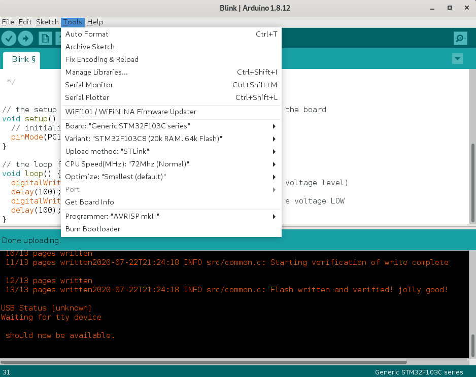
Figure 1.11 – The Tools menu with the necessary options for the Blue Pill
The IDE should be ready to start coding for the Blue Pill. Before that, we need to install an interface called ST-Link/V2 to flash (upload) our code to the Blue Pill. We cannot upload our compiled program directly to the Blue Pill, as with other microcontroller boards, through the micro-USB cable. One easy way to do this is to use the ST-Link/V2 interface, which is a Single Wire Interface Module (SWIM) using only four wires.
The ST-Link/V2 is a USB interface that is used for programming and debugging STM32 microcontroller applications and is mainly used for uploading a program to the Blue Pill microcontroller board.
Before connecting the ST-Link/V2, you will need to install its driver on your computer. The following explains how to install the ST-Link/V2 driver for Windows. Download the driver from here: https://www.st.com/en/development-tools/stsw-link009.html.
Download and uncompress the zip file and run either dpinst_amd64.exe or dpinst_x86.exe, depending on whether you are using a 32-bit or 64-bit computer. Most of the recent ones are 64 bits. Follow the displayed instructions on how to install its driver.
Here are the instructions for installing the ST-Link/V2 on macOS: https://www.st.com/en/development-tools/stsw-link007.html#overview.
Here are the instructions for installing the ST-Link/V2 on Linux: https://freeelectron.ro/installing-st-link-v2-to-flash-stm32-targets-on-linux/.
Important note
If you run the Arduino IDE on Linux, run the IDE as root to get USB access privileges.
Alternatively, you can try this open source toolset for installing the ST-Link/V2 on Windows, macOS, or Linux: https://github.com/stlink-org/stlink.
The Arduino IDE provides a serial monitor, accessed by clicking on Tools/Serial Monitor from the IDE's main menu. It will show data sent from the Blue Pill to the USB serial port by using special coding functions. Chapter 5, Humidity and Temperature Measurement, explains how to use the serial monitor. It can be used to show on the computer screen data obtained from sensors, values of variables, and other similar operations.
The next section describes how to run a simple program that will make an LED blink once a second using both the MPLAB and the Arduino IDEs. This will be a practical example to get you familiar with programming the Blue Pill and the Curiosity Nano boards.
Your first project – a blinking LED
This small project demonstrates how to connect an LED to a microcontroller board and how to program one of their I/O ports so that you can turn the LED on, wait for 1 second (1,000 milliseconds), turn the LED off, wait another second, and turn the LED on, in an endless loop.
The project also demonstrates how to upload a compiled program to a microcontroller board. This is an important starter project, since you can later reuse this code for sending a signal to a port and controlling a more complex application, such as a fan. This is like a Hello World project for microcontroller boards! We will run this project for both the Blue Pill and the Curiosity Nano microcontroller boards using their respective IDEs.
Running the blinking LED example with the Blue Pill board
This small project demonstrates how to turn an LED on for 1 second, and then off for 1 second, repeatedly. Of course, it also demonstrates how to declare and use an I/O port from the Blue Pill as an output.
Tip
Before you start, be careful when you manipulate the Blue Pill and Curiosity Nano boards. They can be damaged by your body's static electricity, so you should touch a big metallic area such as a desk frame before manipulating them. You can also wear an anti-static wrist strap. By doing that you are discharging your static electricity. As a general rule, avoid touching the header pins with your bare hands.
We will now look at how to connect the electronic components to the solderless breadboard and the Blue Pill:
- You will need to insert the Blue Pill board into the breadboard. Do it carefully, since the header pins may bend.
- Connect the LED to the breadboard. Now, connect one pin of the 220-ohm resistor to the longest pin (leg) of the LED, as shown in the following diagram. Connect the other pin of the resistor to the pin labeled C13 of the Blue Pill.
- Connect the shortest pin of the LED to the ground pin labeled G or GND of the Blue Pill using a wire. Remember that the holes of each column of the breadboard are internally connected.
- Now, connect the ST-Link/V2 module pins to the Blue Pill pins as follows. The ST-Link/V2 pins are labeled on one of its sides. The Blue Pill's pins are labeled on its bottom side.
- Connect the Blue Pill's CLK pin to the ST-Link/V2's SWCLK pin.
- Connect the Blue Pill's DIO pin to the ST-Link/V2's SWDIO pin.
- Connect the Blue Pill's GND pin to the ST-Lin/V2's GND pin
- Connect the Blue Pill's 3V3 pin to the ST-Link/V2's 3.3 V pin.
The connections between the ST-Link/V2 and the Blue Pill are shown in Figure 1.12:
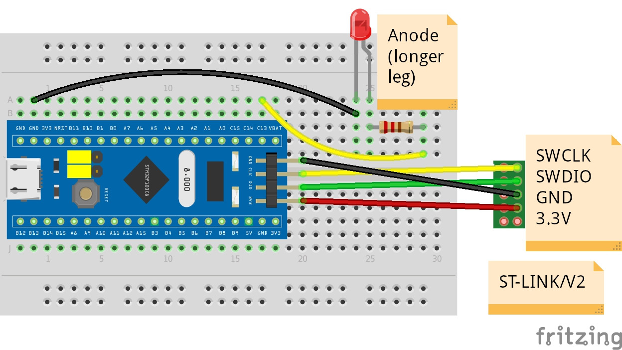
Figure 1.12 – The Blue Pill, LED, and ST-Link/V2 connections
Figure 1.12 shows the connections we have made. Please note that here there are four DuPont wires connected between the Blue Pill and the ST-Link/V2. Figure 1.13 shows a photo of the connections between the Blue Pill and the ST-Link/V2:
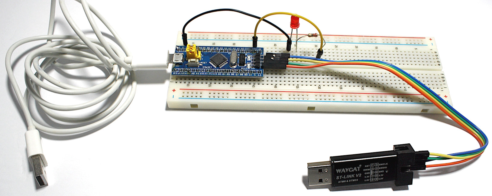
Figure 1.13 – The Blue Pill connections, including the ST-Link/V2
Once you have connected the Blue Pill to the ST-Link/V2, we will continue as follows:
- Plug in the ST-Link/V2 to your computer. Also, disconnect the micro-USB cable from the Blue Pill (the white cable from the picture). You don't need this for uploading the program to the Blue Pill.
- Download the program called Blink_Blue_Pill.ino from the Chapter 1 folder located in the book's GitHub repository.
- Download the .ino file from GitHub and open it with the Arduino IDE, which will make a new folder to store the program in. This is a normal practice of the Arduino IDE. Don't worry if you don't understand the code yet. We will explain its C code programming in the next chapter.
- Click on the upload icon on the IDE to compile and upload the program to the Blue Pill. You will see the Blue Pill's onboard LED and the LED that you connected, blinking once per second if everything went well. The onboard LED is internally connected to the PC13 pin. Try to change the blinking rate by changing the 1,000 millisecond value from the delay(1000) function.
- Once you have uploaded the program to the Blue Pill, it is no longer necessary to keep the ST-Link/V2 connected to it, so you can disconnect it if you want. Now you can connect the Blue Pill's micro USB cable to your computer or a USB power bank. Your compiled program will be kept in Blue Pill's memory and will run every time you power it.
And there you have it! You have completed your first electronic circuit with the Blue Pill. If your LED is blinking, well done!
This project can also be done with Arduino microcontroller boards, such as the Arduino Uno. Just change the port number in the Arduino code and use the Arduino IDE to compile and upload the program. Write 13 Instead of PC13 in the code for the port number and connect the resistor to digital port number 13 of the Arduino Uno board.
Running the blinking LED example on the Curiosity Nano board
Now let's try the LED blinking example on the Curiosity Nano board. We don't need to connect an interface programmer (such as the ST-Link/V2) to upload your program to the Curiosity Nano, because this board already has the necessary hardware and software components to do so. These are the steps for connecting the Curiosity Nano and the LED:
- Insert the Curiosity Nano board into the solderless breadboard. Do this carefully because its legs may bend. Also, don't forget to touch a big metallic object before handling the Curiosity Nano to discharge the static electricity from your body.
Connect the LED to the breadboard. Now, connect one pin of the 220-ohm resistors to the longest pin of the LED, as shown in Figure 1.14. Connect the other pin of the resistor to the pin labeled RE0 pin on the Curiosity Nano. The RE0 pin is internally connected to the onboard yellow LED from the Curiosity Nano:
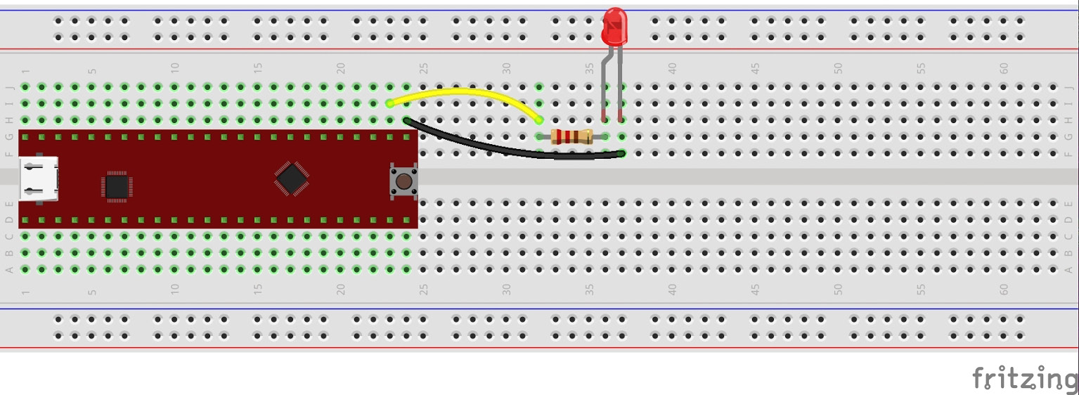
Figure 1.14 – Diagram showing the Curiosity Nano and the LED connection
- Connect the shortest leg of the LED to the ground pin labeled GND of the Curiosity Nano using a wire, as shown in Figure 1.14. Any GND pin from the Curiosity Nano will do. Remember that the holes of each breadboard column are internally connected.
The electronic circuit with the Curiosity Nano is shown in Figure 1.15. In this diagram, you can visualize with more detail how the LED and the resistor are connected to the board:
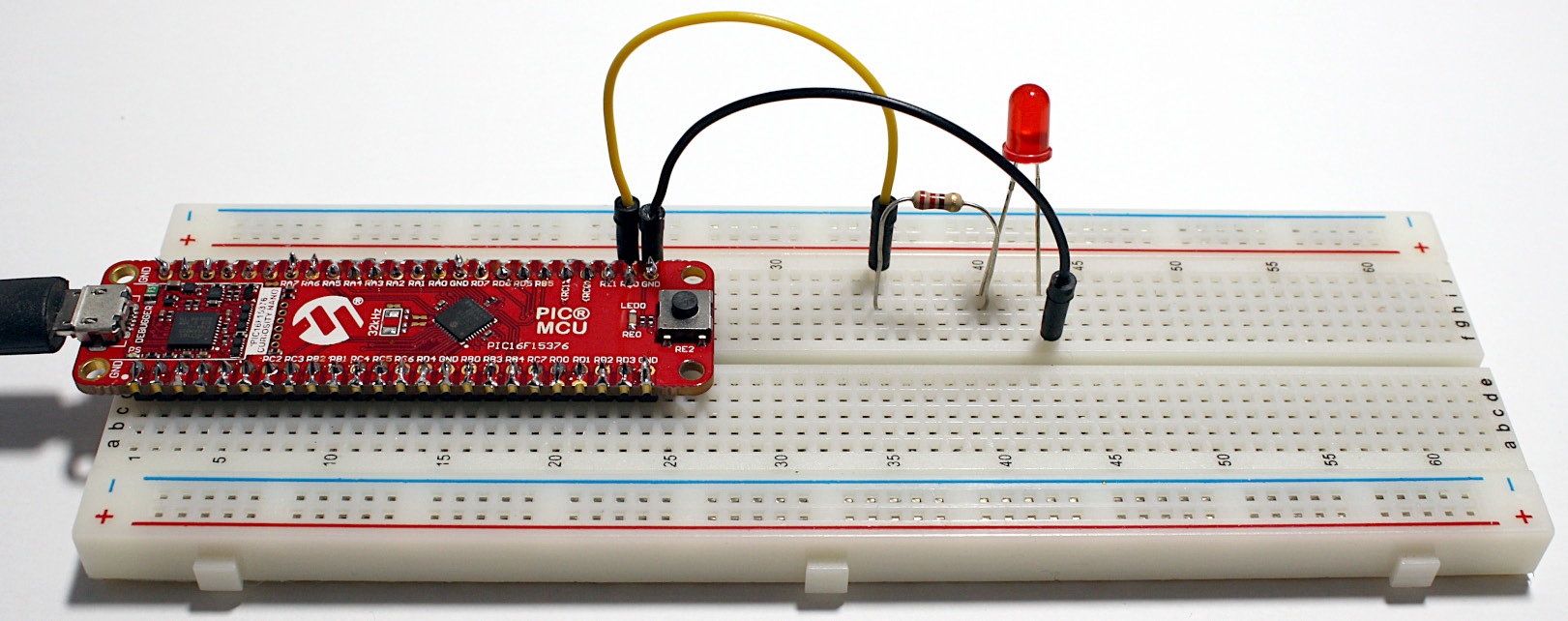
Figure 1.15 – The Curiosity Nano and its LED connection
- Connect the Curiosity Nano to your computer using a micro-USB cable.
- Now, let's download and run the demo project that contains the C program that makes the LED blink on the Curiosity Nano.
- Download the file called 16F15376_Curiosity_Nano_LED_Blink_Delay.zip from the Chapter 1 folder located in the book's GitHub repository.
- Unzip the file and open the project from the MPLAB X IDE. Select the tab with the main.c label. That is the C program that you need to run. Now, click on the run icon (the green triangle) on the MPLAB X.
At this point, the IDE will compile and upload the program to the board. After a few seconds, the onboard yellow LED and the breadboard's LED should be blinking once per second. If this is happening, well done!
Once you connect the LED to the Curiosity Nano and see that the LED is blinking once a second, try to change the code in the IDE a little bit by blinking the LED faster or slower. You can do this by changing the value of the milliseconds from the __delay_ms(1000); function and don't forget that the value from that function is stated in milliseconds (there are 1,000 milliseconds in a second).
Summary
In this chapter, we have defined what a microcontroller is, as well as its capabilities and limitations. We have also looked at what integrated circuits are (keeping in mind that microcontrollers are a type of integrated circuit) and how their pins are arranged in packages. In addition to this, we analyzed what ports are in microcontroller boards. This is important to know because at some point in future projects, you will need to identify the order of those pins in order to connect sensors or other devices to them. Table 1.1 showed the hardware description and operating voltage for both the Curiosity Nano and the Blue pill, which is 5 volts.
We then looked at a brief introduction to electronics and the main electronic components used in this and other chapters. We explored how to install two integrated development environment tools for programming the two microcontroller boards used in this book. The two boards have two different ways of uploading a compiled program to them. It is important to compare how two different microcontroller boards work to analyze their capabilities and decide which one you can use in future projects.
Finally, we showcased an initial program on both microcontroller boards that demonstrates how to turn an LED on and off, which can work as a baseline for more complex and detailed projects.
The next chapter contains a concise C programming tutorial, which will be very useful for programming the exercises of the remaining chapters.
Further reading
- Ball, S. (2002). Embedded Microprocessor Systems: Real-World Design. Burlington, MA: Newnes/Elsevier Science.
- Gay, W. (2018). Beginning STM32: Developing with FreeRTOS, libopencm3, and GCC. St. Catharines: Apress.
- Horowitz, P., Hill, W. (2015). The Art of Electronics. [3rd ed.] Cambridge University Press: New York, NY.
- Microchip (2019). PIC16F15376 Curiosity Nano Hardware User Guide. Microchip Technology, Inc. Available from: http://ww1.microchip.com/downloads/en/DeviceDoc/50002900B.pdf.
- Mims, F.M. (2000). Getting Started in Electronics. Lincolnwood, IL: Master Publishing, Inc.