
Chapter 3: Turning an LED On or Off Using a Push Button
In this chapter, we will review and practice how to turn an LED on or off using a push button connected to a microcontroller board. A push button is a practical component that acts like a switch and is used for closing or opening an electronic circuit. We can use them to initialize or activate a process in a microcontroller board. Consequently, the input data provided by a push button is important in many microcontroller applications that require human intervention. Specifically, we will cover the following main topics in this chapter:
- Introducing push buttons
- Understanding electrical noise from push buttons
- Connecting an LED to a microcontroller board port and using an internal pull-up resistor
- Testing out the push button
By the end of this chapter, you will have learned how to connect a push button to the Curiosity Nano and the Blue Pill microcontroller boards, as well as how to program the push button's input to turn an LED on or off. You will also have learned how to reduce the problem of electrical noise in push buttons. Trying to solve this problem is not trivial, as we will see in this chapter. In particular, the Understanding electrical noise from push buttons section explains that not all push buttons work 100% free of manufacturing errors, and electrical noise can be present in them when they are used.
Technical requirements
The software tools that we will use in this chapter will be the MPLAB-X and Arduino IDEs. The code in this chapter can be found in this book's GitHub repository at the following URL:
https://github.com/PacktPublishing/DIY-Microcontroller-Projects-for-Hobbyists/tree/master/Chapter03
The Code in Action video for this chapter can be found here: https://bit.ly/3cXfZLM
The code examples in this repository will be used to turn an LED on or off using the Curiosity Nano and the Blue Pill microcontroller boards. The IDEs' installation guides and uses were explained in Chapter 1, Introduction to Microcontrollers and Microcontroller Boards. In this chapter, we will also use the following pieces of hardware:
- A solderless breadboard.
- The Blue Pill and Curiosity Nano microcontroller boards.
- A micro-USB cable for connecting your microcontroller boards to a computer.
- The ST-Link/V2 electronic interface, which is needed to upload the compiled code to the Blue Pill. Bear in mind that the ST-Link/V2 requires four female-to-female DuPont wires.
- One LED. Any color will do. We prefer to use a red one for our exercises.
- One 220-ohm resistor rated at one-quarter watt.
- Four male-to-male DuPont wires for connecting the resistor and the push button to the boards.
- A regular, normally open push button.
The next section provides a brief introduction to push buttons, which are used in electronic circuits.
Introducing push buttons
A push button is an electronic device that basically acts like a mechanical switch; it can be used for either closing or opening an electrical or electronic circuit. They are also called momentary push buttons, or pushbuttons. Push buttons are made with hard materials such as plastic and have a tiny metal spring inside that makes contact with two wires or contacts, allowing electricity to flow through them if the button is pressed (in normally open push buttons) or when it is depressed (in normally closed push buttons). When the push button is off, the spring retracts, the electrical contact is interrupted, and electrical current will not flow through the contacts. Push buttons are useful for manually controlling or initializing a process in an electrical or electronic circuit, including applications that contain microcontroller boards. The following image shows a normally closed (left) and a normally open (right) push button:

Figure 3.1 – Normally closed (left) and normally open (right) push buttons
As you can see in Figure 3.1, the normally open push button (on right) looks depressed. Note that the pins are connected to a microcontroller board.
Note
Normally open and normally closed push buttons may look exactly the same, depending on their manufacturers and models. If you are unsure, try your button with a microcontroller board and see what type of push button it is. If the push button sends a logic signal to the microcontroller board without you needing to press it, this means that it is a normally closed push button. In this chapter, you will learn how to connect a push button to a microcontroller board.
A typical application of a push button in microcontroller board projects is to connect or disconnect either the ground or a positive voltage from an I/O pin on the microcontroller board. This voltage change that's made by the push button can be seen by the microcontroller board through its I/O pin (port); this initializes a process in the microcontroller board.
There are different types of push buttons in terms of size. Large and robust ones are used for some industrial applications where an operator needs to quickly identify and push them. Smaller buttons are typically used in electrical appliances and devices, such as computer keyboards and landline telephones. In this chapter, we will use a small push button that is commonly found in many electronic kits and in kits that include microcontroller boards. In fact, the Blue Pill and the Curiosity Nano microcontroller boards have small push buttons in their circuits. They can be used in both boards for resetting the programs that run on them. There are two main types of push buttons: normally open and normally closed push buttons. Let's look at them in more detail:
- Normally open push buttons. In this type of button, its switch always remains open when it is not pressed; that is, it does not close an electrical circuit. It makes an electrical contact (closes a circuit) every time we press it. When we press the push button down, its internal switch closes. These are the most common types of push buttons. They can be useful for momentarily activating or initializing a process; for example, pressing the push button briefly to reset a microcontroller board.
- Normally closed push buttons. In its default state, this button can close a circuit, meaning that its switch is normally closed without us having to press the push button. We open the switch (hence the circuit where it is connected to) when we press this type of push button. These buttons can be useful when we need to momentarily turn off or interrupt an electrical/electronic circuit. For example, we can open the connection of a sensor to a microcontroller board if we want to stop reading the sensor for whatever reason.
The next section describes a problem that is present in many push buttons, known as electrical noise. This type of noise can sometimes be very difficult (but not impossible) to minimize.
Understanding electrical noise from push buttons
Electrical noise can be generated in many push buttons. This can negatively affect the functionality of an electronic circuit where the push button is connected, and it can have unpredictable results in a microcontroller board.
A common problem with push buttons is that they are not perfect. They don't close their switch instantly, and in many cases, electrical noise can be produced. This may happen because not all the push buttons are free of manufacturing errors. If we try to connect a push button directly to a microcontroller's I/O port, every time we press the button, it seems that we do it right. To us, it seems like we pressed it only once. However, to the microcontroller board, it looks like the button was pressed many times for extremely short periods of time, and this is because of electrical noise that is generated in the push button. Electrical noise can be defined as random electrical levels or signals coupling with an electronic circuit. This electrical disturbance or interference can vary greatly, from very small voltages to high voltage levels, and its frequency can also change randomly. There are many sources that generate electrical noise, including heat, faulty electronic components, mechanical movement, and loose electrical connections in a circuit, among other sources.
The undesired electrical noise from push buttons is almost always generated by something called bouncing, which is caused by the friction and mechanical movements of the push button's internal metal parts and spring. We need to debounce the push button to diminish its electrical noise and thus properly close a circuit (if we are using a normally open push button) in a clean and efficient way. If we don't debounce a push button, its internal switch may close a circuit erratically every time we press the push button, which will affect the functionality of the entire circuit or microcontroller board's input. The data signal that's generated by a push button should be either zero volts (logical LOW) or 3.3 volts (logical HIGH). If we don't debounce a push button, it will create electrical noise that possibly changes those logical levels, and thus the microcontroller board may not recognize them as such.
Important
The HIGH logic level voltage used in both the Blue Pill and the Curiosity Nano boards is 3.3 volts. Remember that in some microcontroller boards, their HIGH logic level is 5 volts instead of 3.3 volts, such as the Arduino family of microcontroller boards.
There are several techniques that deal with electrical noise in push buttons. For example, this type of noise can be greatly minimized by either connecting some electronic components to a push button, or via coding, as we will see in the next few sections.
Debouncing a push button via hardware
One way to reduce electrical noise from a push button is to connect a capacitor and two resistors (this is also called RC debouncing circuit, a resistor-capacitor network, or an RC filter) connected to the push button, as shown in the following diagram. When we press the push button, the capacitor will be charged. When we release the button, the capacitor will retain its charge for a very short period of time, and the resistor that is connected to it will discharge it after that time. That capacitor's charge represents a HIGH logic voltage, and it can be used in a microcontroller board. Any transient electrical noise that occurs during the capacitor's charge time can be ignored because the capacitor is providing a HIGH logical value in the meantime:
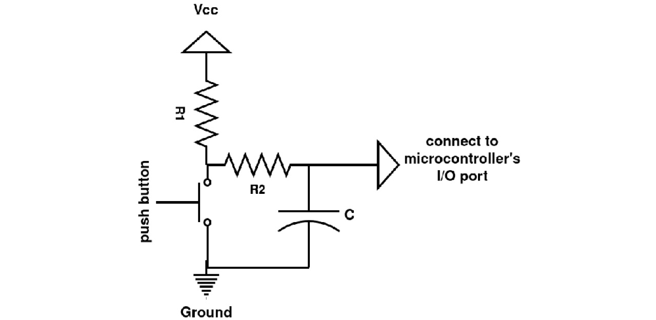
Figure 3.2 – An RC debouncer connected to a push button
The preceding diagram contains two resistors, R1 and R2, a normally open push button, and a capacitor, C. The resistors and the capacitor form an RC debouncer. Remember that Vcc means positive voltage, which is 3.3 volts for the Curiosity Nano and Blue Pill. Generally, you can obtain Vcc from one of the pins of the microcontroller board labeled 3.3V or Vcc. In addition, you can connect the RC debouncer to one of the microcontroller pins labeled as ground. As we saw in the preceding diagram, the three electronic components can be used to reduce electrical noise in the push button. The typical values for R1, R2, and C are 10K ohms, 10K ohms, and 0.1 microfarads, respectively, although you may need to change those values if the RC debouncer is not working effectively, because the electrical noise is not always the same in each push button. The mathematical formula for calculating the RC debouncer is thoroughly explained Ganssle, J.G. (2008), A guide to debouncing.
We included the RC debouncer in this section as a reference, just in case the debouncing method via software does not work for you. The next section will show you how to debounce a push button using software only.
Debouncing a push button via software
We can minimize the spurious electrical noise from a push button via coding. A trick that we can use in the code is to ignore the electrical noise for a very short period of time (usually some dozens of milliseconds), right after we press the push button connected to our circuit. The following diagram shows how to connect a push button directly to a microcontroller board's I/O port to perform debouncing via software:

Figure 3.3 – A push button connected to an I/O port with a pull-down resistor
The preceding diagram shows a pull-down resistor, R, that is forcing the input port from the microcontroller board to receive zero volts (logical LOW), which is connected to ground, while the push button is not being pressed. A typical value for the pull-down resistor, R, is 10k ohms. We can use a pull-down resistor when we need to constantly input a LOW level to the microcontroller board's I/O port, and just change to a logical HIGH level when we press the push button. This can be useful for momentarily starting a process, for example, turning on a light connected to our circuit. The following diagram shows how to connect a pull-up resistor to a microcontroller port, forcing its input to be 3.3 volts (Vcc):

Figure 3.4 – A push button connected to an I/O port with a pull-up resistor
The resistor's value (R) in the preceding diagram is typically 10K ohms.
Important note
You need to connect either a pull-down or pull-up resistor to a microcontroller's input port, because if you don't connect anything to the port (this can happen when the push button is not being pressed), the port will present an undetermined (random) voltage at its input due to its internal electronics arrangement. This is called a floating input voltage.
The preceding diagram includes a normally open push button. Once the push button is pressed, the input voltage will change to a logical HIGH level, or 3.3 volts. Remember that the logical HIGH level can be 5 volts, depending on the microcontroller board that you are using. The Vcc voltage and the ground are connected to the microcontroller board.
Fortunately, many microcontrollers provide internal pull-up and pull-down resistors that are connected to their I/O ports that can be activated via coding. The Blue Pill contains both! This means that we can connect a push button directly to its I/O ports, without connecting an external resistor, and just activate the board's internal pull-up or pull-down resistors via software. This speeds up prototyping development that requires the use of push buttons, but this may not always be the ideal solution.
The following diagram shows two ways of connecting a push button directly to an I/O port. This port already has a pull-up or a pull-down resistor that's been activated via software:

Figure 3.5 – Push buttons connected directly to an I/O port
As you can see, the debouncing method via software does not use the RC debouncing that's connected to the push button. This method works most of the time, and it saves you time and effort. However, you should experiment and try out both methods if the electrical noise from the push button is persistent.
Each debouncing method has its trade-offs. In the hardware-based method, you will need to connect some electronic components to the push button. You will also need to buy those extra components. In the software-based method, where you will be using the microcontroller's internal pull-up or pull-down resistors, you don't need to connect any extra components to the push button, but you will need to add more lines of code to your program to deal with the debouncing, and these instructions may take up some valuable processing cycles from your microcontroller. Despite this, we recommend that you use the software-based debouncing method because it is simple to implement.
The next section deals with examples that show you how to connect a push button to the Blue Pill and Curiosity Nano microcontroller boards, as well as how to debounce it via software.
Connecting an LED to a microcontroller board port and using an internal pull-up resistor
In this section, you will learn how to connect a push button to both the Blue Pill and the Curiosity Nano boards. This is a simple exercise for these microcontroller boards, and it demonstrates how to use a push button to send a logical LOW level signal to a microcontroller board to turn an LED connected to it on or off. If we want to use a push button in our electronic circuit example, we will need to connect it to an input port from a microcontroller board. Also, remember that we should debounce our push button to avoid undesirable results.
The following subsection will show you how to debounce a push button that is connected to the Blue Pill via coding. This is the simplest way to debounce a push button and you can use this method in other chapters of this book.
Debouncing a push button via software connected to the Blue Pill
In this section, we will show you a Fritzing diagram, and then a photo that shows how everything is connected. We will also look at some code that demonstrates how to debounce the push button via software.
The following is a Fritzing diagram that shows how to connect a push button directly to an I/O port that is already using its internal pull-up resistor. The LED and its respective resistor are connected to the Blue Pill's port number; that is, B12:

Figure 3.6 – A Blue Pill using its internal pull-up resistor with the push button
As you can see, the LED will turn on or off every time we press the push button.
Please note that in the preceding image, the push button is connected to the center of the breadboard, to the right of the microcontroller board. Follow these steps to connect the push button and the LED to the Blue Pill, as shown in the preceding image:
- Insert the Blue Pill into the solderless breadboard.
- Insert the push button into the breadboard and connect one of its pins to the Blue Pill's ground pin using a DuPont wire.
- Connect another pin from the push button to port B0 of the Blue Pill using a DuPont wire.
- Insert a 220-ohm resistor into the breadboard and connect one of its pins to port B12 of the Blue Pill using a DuPont wire.
- Insert the LED into the breadboard, connecting its anode to the other resistor's pin.
- Connect the LED's cathode to one of the ground pins of the Blue Pill using a DuPont wire.
The following image shows how to connect the push button to the Blue Pill, based on the Fritzing diagram shown previously:

Figure 3.7 – Connecting the push button to the Blue Pill's cathode, and then to one of the ground pins from the Blue Pill using a DuPont wire
As you can see, the Blue Pill board has ground (G) pins on the top and bottom rows of pins. This facilitates the component connections in the circuit.
Remember that you will need to connect the ST-Link/V2 electronic interface to the Blue Pill to upload the program to it from the Arduino IDE, as explained in Chapter 1, Introduction to Microcontrollers and Microcontroller Boards.
The following code shows how to debounce a push button via software on the Blue Pill. You can find this code file in this book's GitHub repository, with comments provided. The file is called internal_pullup_debounce_Blue_Pill.ino:
#define PinLED PB12
#define Pinpushbutton PB0
void setup() {
pinMode(PinLED, OUTPUT);
pinMode(Pinpushbutton, INPUT_PULLUP);
}
int reading_pushbutton;
int ledState = HIGH;
int buttonState;
int lastButtonState = LOW;
unsigned long lastDebouncingTime = 0;
unsigned long debouncingDelay = 50;
void loop() {
reading_pushbutton=digitalRead(Pinpushbutton);
if (reading_pushbutton!= lastButtonState) {
lastDebouncingTime = millis();
}
if ((millis() - lastDebouncingTime) > debouncingDelay) {
if (reading_pushbutton!=buttonState) {
buttonState = reading_pushbutton;
if (buttonState == HIGH) {
ledState = !ledState;
}
}
}
digitalWrite(PinLED, ledState);
lastButtonState = reading_pushbutton;
}
The preceding code waits 50 milliseconds once the push button has been pressed and toggles the LED value. This value is experimental, so you may need to change it if your push button is working erratically.
Important Note
The Blue Pill's I/O ports are referenced in the Arduino IDE with the letter P. For example, port B12 is referenced as PB12 in the IDE. In addition, the port labels (names) must be written in capital letters.
As shown in the preceding code, it continuously reads the port B0 of the Blue Pill. If the push button is pressed, port B0 is connected to ground by the push button. Then, the B12 output port sends out a HIGH logical level and turns on the LED connected to B12. If the push button is not pressed, the B12 port sends out a LOW logical level.
Tip
You can also debounce a push button via software if you are using an Arduino microcontroller board. In fact, the software-based debouncing method we used in this chapter is based on the method that's used in Arduino boards, as explained here:
https://www.arduino.cc/en/Tutorial/BuiltInExamples/Debounce
If your LED turns on and off when you press the push button, congratulations! Pay attention to how the microcontroller board reacts when you press the push button. If the LED turns on erratically several times when you just press the push button, you may need to change either the resistor or capacitor values if you are doing RC debouncing, or change the millisecond waiting value if you are debouncing the push button via software.
The next section describes how to debounce a push button via software connected to the Curiosity Nano microcontroller board.
Turning an LED on or off with a push button on the Curiosity Nano
In this section, we use the Curiosity Nano to debounce a push button via software by waiting some milliseconds once the push button has been pressed. We can use the __delay_ms() function for this. Remember that the function is written with two underscore symbols (__).
The following Fritzing diagram shows how to connect the push button to the Curiosity Nano:

Figure 3.8 – A push button directly connected to the Curiosity Nano board
Please note that the push button is connected to the center of the breadboard, to the right of the microcontroller board.
According to the preceding image, here are the steps for connecting all the components:
- Insert the Curiosity Nano into the solderless breadboard.
- Insert a push button into the breadboard and connect one of its pins to the Curiosity Nano's ground pin using a DuPont wire.
- Connect another pin from the push button to port RA0 of the Curiosity Nano using a DuPont wire.
- Insert a 220-ohm resistor into the breadboard and connect one of its pins to the port RD2 of the Curiosity Nano using a DuPont wire.
- Insert the LED into the breadboard, connecting its anode to the other resistor's pin.
- Connect the LED's cathode to one of the ground pins of the Curiosity Nano using a DuPont wire.
The following image shows how everything is connected:
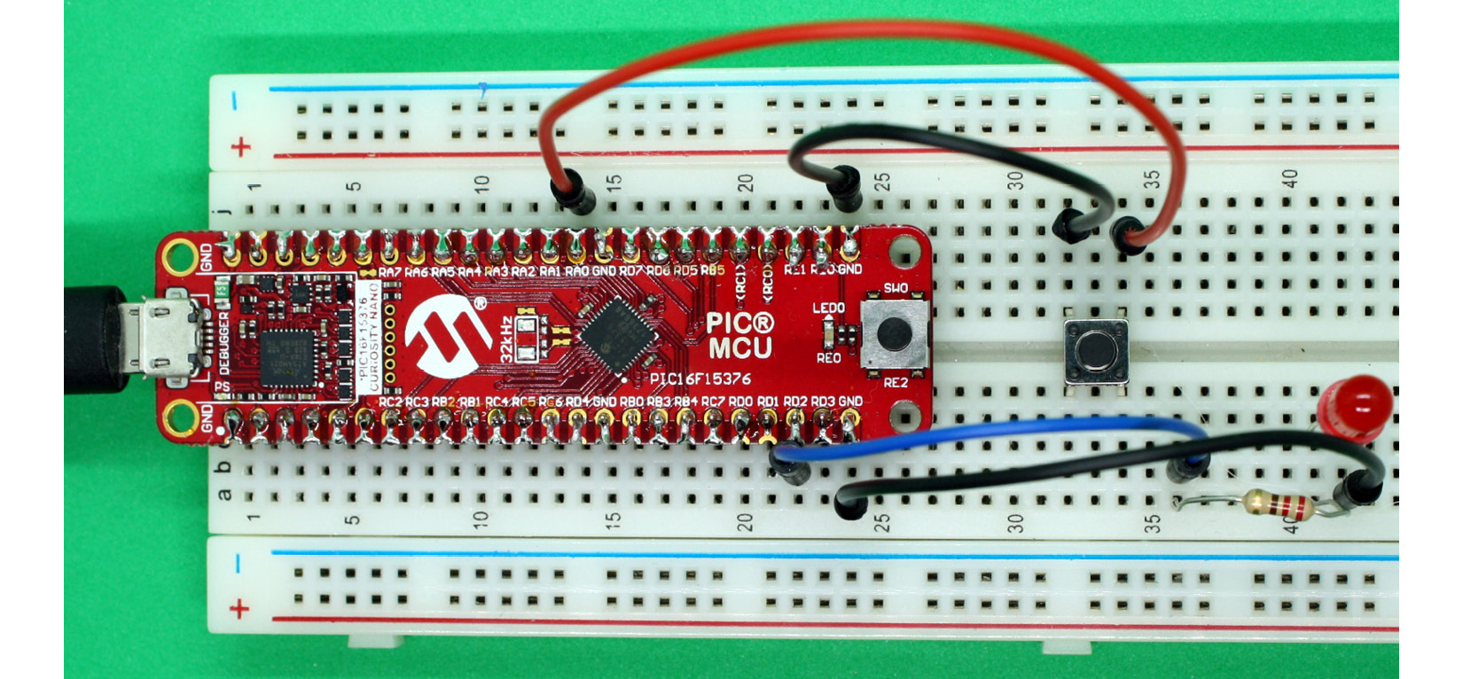
Figure 3.9 – The Curiosity Nano and a push button connected to it
In the preceding image, you can see that the Curiosity Nano has ground (GND) pins in both the upper and lower rows of pins. This allows us to wire the components in the circuit.
We have created a project for the MPLAB-X IDE, which can found in this book's GitHub repository. It contains comments explaining each line of code. You will need to uncompress its ZIP file first to open the project in the MPLAB-X IDE. This project file is called 16F15376_Curiosity_Nano_pushbutton.X.zip.
The following code from that project shows how software-based debouncing is done:
#include <xc.h>
#include <stdio.h>
#include "mcc_generated_files/mcc.h"
int reading_pushbutton=0;
void main(void)
{
SYSTEM_Initialize();
IO_RD2_SetDigitalOutput();
IO_RA0_SetDigitalInput();
IO_RA0_SetPullup();
IO_RD2_SetLow();
while (1)
{
reading_pushbutton=IO_RA0_GetValue();
__delay_ms(100);
reading_pushbutton=IO_RA0_GetValue();
if (reading_pushbutton==LOW){
IO_RD2_Toggle();
}
}
}
The preceding code reads the value from the push button and waits 100 milliseconds; then, it reads it again to see if the push button is still being pressed. We found this 100-millisecond value experimentally and it seems to work most of the time. Remember that you may need to adjust it, depending on how your own push button behaves in your circuit.
This is a slightly different approach than the one we used in the Blue Pill. We coded the waiting time to try and ignore some electrical noise that may occur during that time. If your LED turns on and off when you press the push button, congratulations! You are now able to connect and use a push button in an electronic circuit connected to a microcontroller board. Remember that a push button may be used to initiate a process or activity in a microcontroller board.
The next section will show you how to check if a push button is working OK, and if it is a normally open or normally closed push button.
Testing out the push button
In this section, we will focus on testing a push button. Before using it with a microcontroller board, it's a good idea to try it out to see if it works mechanically, and testing allows us to find out if the push button is normally closed or normally opened. The following image shows how to connect all the components to try out the push button:

Figure 3.10 – Connecting the push button to an LED and a battery pack
As you can see, we don't need to connect a push button to a microcontroller board to test it. Here are the steps for connecting the components and testing the push button:
- Connect the batteries' positive (+) terminal to one pin of the push button.
- Connect the other push button pin to the 220-ohm resistor.
- Connect the 220-ohm resistor to the LED's anode pin.
- Connect the LED's cathode pin to the batteries' negative (-) terminal. Be careful when connecting the LED's pins. If it is connected in reverse, the LED will not turn on.
- Once you've connected everything, if the LED turns on without you pressing the push button, this means that the push button is of the normally closed type. If it does, the LED should turn off when you press the push button. If the LED turns on every time you press the push button, this means that it is a normally open one.
- Press the push button several times. If the LED turns on and off erratically, or if the LED does not turn on at all, the push button may be faulty and you will need to replace it, assuming that the batteries have enough voltage.
Connecting the batteries to the push button and the LED should be enough to see if the push button works.
Summary
In this chapter, we learned what a push button is and how can we reduce the problem of electrical noise that many push buttons have, a process called debouncing. This process can be done either via software or hardware. We also reviewed the importance of push buttons in some electronic projects that require human intervention – for example, how to manually restart a microcontroller board when we press its on-board push button. Using a push button in an electronic circuit containing a microcontroller board is important because you are programming a user interaction there, so a user can start a process in the microcontroller board.
The next chapter will focus on how to connect a photoresistor (a sensor that measures the amount of light in the environment).
Further reading
- Ganssle, J.G. (2008). A guide to debouncing. Technical Report. Baltimore, MD: The Ganssle Group.
- Gay, W. (2018). Beginning STM32: Developing with FreeRTOS, libopencm3 and GCC. St. Catharines: Apress.
- Horowitz, P., Hill, W. (2015). The art of electronics. [3rd ed.] Cambridge University Press: New York, NY.
- Microchip (2019). PIC16F15376 Curiosity Nano Hardware User Guide. Microchip Technology, Inc. Available from http://ww1.microchip.com/downloads/en/DeviceDoc/50002900B.pdf
- Mims, F.M. (2000). Getting started in electronics. Lincolnwood, IL: Master Publishing, Inc.
- Ostapiuk, R. & Tay, I. (2020). Fundamentals of the C programming language. Microchip Technology, Inc. Retrieved from https://microchipdeveloper.com/tls2101:start
- Ward, H.H. (2020). C programming for the PIC microcontroller. New York, NY: Apress.