
Chapter 6: Materials and Effects with URP and Shader Graph
Welcome to the first chapter of Part 2! I am super excited that you have reached this part of the book because here we will dive deep into different graphics and audio systems of Unity to dramatically improve the look and feel of the game. We will start this part with this chapter, where we will be discussing what the Shader of a Material is and how to create our own Shaders to achieve several custom effects that couldn't be accomplished using default Unity Shaders. We will be creating a simple water animation effect to learn this new concept.
In this chapter, we will examine the following Shader concepts:
- Introduction to Shaders
- Creating Shaders with Shader Graph
Introducing Shaders
We created Materials in the previous chapter, but we never discussed how they internally work and why the Shader property is super important. In this first section of the chapter, we will be exploring the concept of a Shader as a way to program the video card to achieve custom visual effects.
In this section, we will cover the following concepts related to Shaders:
- Shader Pipeline
- Render Pipeline and URP
- URP Built-in Shaders
Let's start by discussing how a Shader modifies the Shader Pipeline to achieve effects.
Shader Pipeline
Whenever a video card renders a 3D model, it needs input data to process, such as a Mesh, Textures, the transform of the object (position, rotation, and scale), and lights that affect that object. With that data, the video card must output the pixels of the object into the Back-Buffer, the image where the video card will be drawing our objects. That image will be shown when Unity finishes rendering all objects (and some effects) to display the finished scene. Basically, the Back-Buffer is the image the video card renders step by step, showing it when the drawing has finished (at that moment, it becomes the Front-Buffer, swapping with the previous one).
That's the usual way to render an object, but what happens between the input of the data and the output of the pixels can be handled through a myriad of different ways and techniques that depend on how you want your object to look; maybe you want it to be realistic or look like a hologram, maybe the object needs a disintegration effect or a toon effect—there are endless possibilities. The way to specify how our video card will handle the render of the object is through a Shader.
A Shader is a program coded in a specific video card language, such as CG, HLSL, or GLSL, that configures different stages of the render process, sometimes not only configuring them but also replacing them with completely custom code to achieve the exact effect we want. All of the stages of rendering form what we call the Shader Pipeline, a chain of modifications applied to the input data until it's transformed into pixels.
Important note
Sometimes, what we called the Shader Pipeline in this book can be also found in another bibliography as the Render Pipeline, and whereas the latter is also correct, in Unity, the term Render Pipeline refers to something different, so let's stick with this name.
Each stage of the pipeline is in charge of different modifications and depending on the video card Shader Model, this pipeline can vary a lot. In the next diagram, you can find a simplified Render Pipeline, skipping advanced/optional stages that are not important right now:

Figure 6.1 – Common Shader Pipeline
Let's discuss each of the stages:
- Input Assembler: Here is where all of the mesh data, such as the vertex position, UVs, and normals, are assembled to be prepared for the next stage. You can't do much here; this process is almost always the same.
- Vertex Shader: In the past, this stage was limited to applying the transformation of the object, the position and perspective of the camera, and some simple but limited lighting calculations. With modern GPUs, you are in charge of doing whatever you want. This stage receives each one of the vertexes of the object to render and outputs a modified one, so basically, you have the chance to modify the geometry of the object here. The usual code here is basically the same as old video cards had, applying the transform of the object, but you can do several effects such as inflating the object along its normals to apply the old toon effect technique or apply some distortions to make a hologram effect (look at the hologram effect in Death Stranding). There's also the opportunity to calculate data for the next stages, but we won't be going that deep for now.
- Culling: For most of the models you are going to render, you will never see the backside of the model's face. Let's take as an example a cube; there's no way to look at the back or inner side of any of its sides because they will be automatically occluded by the other sides. Knowing that, rendering both sides of each face of the cube, even if the backside can't be seen, makes no sense, and luckily this stage takes care of that. Culling will determine whether the face needs to be rendered based on the orientation of the face, saving lots of pixel calculation for occluded faces. You can change this to behave differently for specific cases; as an example, we can create a glass box that needs to be transparent to see all sides of the box.
- Rasterizer: Now that we have the modified and visible geometry of our model calculated, it's time to convert it into pixels. The Rasterizer creates all pixels for the triangles of our mesh. Lots of things happen here but again, we have very little control over that; the usual way to rasterize is just to create all pixels inside the edges of the mesh triangles. We have other modes that just render the pixels on the edges to see a wireframe effect, but this is usually used for debugging purposes:
Figure 6.2 – Example of figures being rasterized
- Fragment Shader: This is one of the most customizable stages of all. Its purpose is simple: just determine the color of each one of the fragments (pixels) that the rasterizer has generated. Here, lots of things can happen, from simply outputting a plain color or sampling a texture to applying complex lighting calculations such as normal mapping and PBR. Also, you can use this stage to create special effects such as water animations, holograms, distortions, disintegrations, and other special effects that require you to modify what the pixels look like. We will explore how we can use this stage in the next sections of this chapter.
- Depth Testing: Before given the pixel as finished, we need to check whether the pixel can be seen. This stage checks whether the pixel's depth is behind or in front of the previously rendered pixel, guaranteeing that regardless of the rendering order of the objects, the nearest pixels to the camera are always being drawn on top of others. Again, usually, this stage is left in its default state, prioritizing pixels that are nearer to the camera, but some effects require different behavior. As an example, in the next screenshot, you can see an effect that allows you to see objects that are behind other objects, such as units and buildings in Age of Empires:
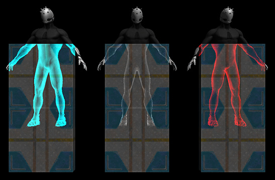
Figure 6.3 – Rendering the occluded parts of the character
- Blending: Once the color of the pixel is determined and we are sure the pixel is not occluded by a previous pixel, the final step is to put it in the Back-Buffer (the frame or image you are drawing). The usual way to do this is to just override whatever pixel was in that position (because our pixel is nearer to the camera), but if you think about transparent objects, we need to combine our pixel with the previous one to make the transparency effect. Transparencies have other things to take into account aside from the blending, but the main idea is that blending controls exactly how the pixel will be combined with the previously rendered pixel in the Back-Buffer.
Shader Pipelines is a subject that would require an entire book, but for the scope of this book, the previous description will give you a good idea of what a Shader does, and the possible effects that it can achieve. Now that we have discussed how a Shader renders a single object, it is worth discussing how Unity renders all objects using Render Pipelines.
Render Pipelines and URP
We have covered how the video card renders an object, but Unity is in charge of asking the video card to execute its Shader Pipeline per object. To do so, Unity needs to do lots of preparations and calculations to determine exactly how and when each Shader needs to be executed. The responsibility of doing this is given to what Unity calls a Render Pipeline.
A Render Pipeline is a way to draw the objects of a scene. At first, it sounds like there should be just one simple way of doing this, such as just iterating over all objects in the scene and executing the Shader Pipeline with the Shader specified in each object's Material, but it can be more complex than that. Usually, the main difference between one Render Pipeline and another is the way in which lighting and some advanced effects are calculated, but they can differ in other ways.
In previous Unity versions, there was just one single Render Pipeline, which is now called the Built-in Render Pipeline. It was a Pipeline that had all of the possible features you would need for all kinds of projects, from mobile 2D graphics and simple 3D graphics to cutting-edge 3D graphics what ones you can find on consoles or high-end PCs. This sounds ideal, but actually, it isn't; having one single giant renderer that needs to be highly customizable to adapt to all possible scenarios generates lots of overhead and limitations that cause more headaches than creating a custom Render Pipeline. Luckily, the latest version of Unity introduced the Scriptable Render Pipeline (SRP), a way to create Render Pipelines adapted for your project.
Thankfully, Unity doesn't want you to create your own Render Pipeline for each project (a complex task), so it created two custom Pipelines for you that are ready to use: URP (formerly called LWRP), which stands for Universal Render Pipeline, and HDRP, which stands for High Definition Render Pipeline. The idea is that you must choose one or the other based on your project requirements (unless you really need to create your own). URP, the one we selected when creating the project for our game, is a Render Pipeline suitable for most games that don't require lots of advanced graphics features, such as mobile games or simple PC games, while HDRP is packed with lots of advanced rendering features for high-quality games. The latter requires high-end hardware to run, while URP runs in almost every relevant target device. It is worth mentioning that you can switch between Built-in Renderer, HDRP, and URP whenever you want, including after creating the project (not recommended):
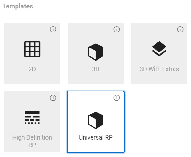
Figure 6.4 – Project wizard showing HDRP and URP templates
We can discuss how each one is implemented and the differences between each, but again, this can fill entire chapters; right now, the idea of this section is for you to know why we picked URP when we created our project because it has some restrictions we will encounter throughout this book that we will need to take into account, so it is good to know why we accepted those limitations (to run our game on all relevant hardware). Also, we need to know that we have chosen URP because it has support for Shader Graph, the Unity tool that we will be using in this chapter to create custom effects. Previous Unity Built-in Pipelines didn't provide us with such a tool (aside from third-party plugins). Finally, another reason to introduce the concept of URP is that it comes with lots of built-in Shaders that we will need to know about before creating our own to avoid reinventing the wheel, and to adapt ourselves to those Shaders, because if you came from previous versions of Unity, the ones you know won't work here, and actually this is exactly what we are going to discuss in the next section of this book: the differences between the different URP Built-in Shaders.
URP Built-in Shaders
Now that we know the difference between URP and other pipelines, let's discuss which Shaders come integrated into URP. Let's briefly describe the three most important Shaders in this Pipeline:
- Lit: This is the replacement of the old Standard Shader. This Shader is useful when creating all kinds of realistic Physics Materials such as wood, rubber, metal, skin, and combinations of them (such as a character with skin and metal armor). It supports Normal Mapping, Occlusion, Metallic and Specular Workflow, and transparencies.
- Simple Lit: This is the replacement of the old Mobile/Diffuse Shader. As the name suggests, this Shader is a simpler version of Lit, meaning that its lighting calculations are simpler approximations of how light works, getting fewer features than its counterpart. Basically, when you have simple graphics without realistic lighting effects, this is the best choice.
- Unlit: This is the replacement of the old Unlit/Texture Shader. Sometimes, you need objects without lighting whatsoever, and in that case, this is the Shader for you. No lighting doesn't mean an absence of light or complete darkness; it actually means that the object has no shadows at all, and it's fully visible without any shade. Some simplistic graphics can work with this, relying on shadowing being baked in the texture, meaning that the texture comes with the shadow. This is extremely performant, especially for low-end devices such as mobile phones. Also, you have other cases such as light tubes or screens, objects that can't receive shadows because they emit light, so they will be seen in full color even in complete darkness. In the following screenshot, you can see a 3D model using an Unlit Shader. It looks like it's being lit, but it's just the texture of the model with lighter and darker colors being applied in different parts of the object:
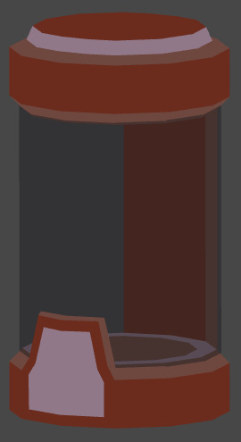
Figure 6.5 – Pod using an Unlit effect to simulate cheap lighting
Let's do an interesting disintegration effect with the Simple Lit Shader to demonstrate its capabilities. You must do the following:
- Download and import a Cloud Noise Texture from any search engine:
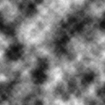
Figure 6.6 – Noise Texture
- Select the recently imported texture in the Project Panel.
- In the Inspector, set the Alpha Source property to From Gray Scale. This will mean the alpha channel of the texture will be calculated based on the grayscale of the image:
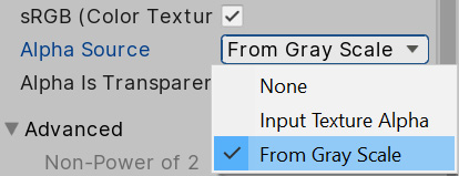
Figure 6.7 – Generate Alpha from Grayscale Texture setting
Important note
The alpha channel of a color is often associated with transparency, but you will notice that our object won't be transparent. The Alpha channel is extra color data that can be used for several purposes when doing effects. In this case, we will use it to determine which pixels are deintegrated first.
- Create a Material by clicking on the + icon in the Project View and selecting Material:
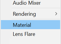
Figure 6.8 – Material creation button
- Create a cube with the GameObject | 3d Object | Cube option at the top menu of Unity:
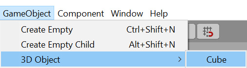
Figure 6.9 – Cube primitive creation
- Drag the created Material from the Project Window to the cube to apply the Material.
- Click in the drop-down menu at the right of the Shader property in the Inspector and look for the Universal Render Pipeline | Simple Lit option:
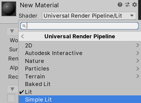
Figure 6.10 – Simple Lit Shader selection
- Select the Material and in Base Map, set the recently downloaded Cloud Noise Texture.
- Check the Alpha Clipping checkbox and set the Threshold slider to 0.5:
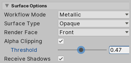
Figure 6.11 Alpha Clipping Threshold Material slider
- You will see how as you move the Alpha Clipping slider, the object starts to disintegrate. Alpha Clipping discards pixels that have less Alpha intensity than the style value:
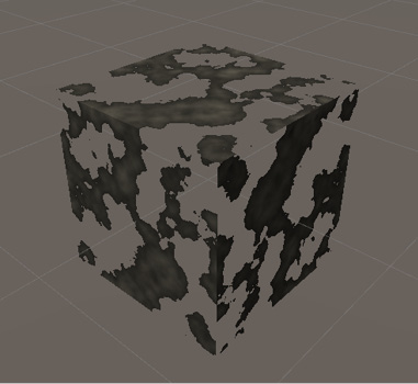
Figure 6.12 Disintegration effect with Alpha Clipping
- Finally, set Render Face to Both to turn off the Culling Shader Stage and see both sides of the cube's faces:
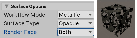
Figure 6.13 Double-sided Alpha Clipping
- Take into account that the artist that creates the texture can configure the Alpha channel manually instead of calculating it from the grayscale, just to control exactly how the disintegration effect must look regardless of the texture´s color distribution.
The idea of this section is not to give a comprehensive guide to all of the properties of all URP Shaders, but to give you an idea of what a Shader can do when properly configured and when to use each one of the integrated Shaders. Sometimes, you can achieve the effect you need just by using existing Shaders. In fact, you can probably do so for probably 99% of the cases in simple games, so try to stick to them as much as you can. But if you really need to create a custom Shader to create a very specific effect, the next section will teach you how to use the URP tool called Shader Graph.
Creating Shaders with Shader Graph
Now that we know how Shaders work and the existing Shaders in URP, we have a basic notion of when it is necessary to create a custom Shader and when it is not necessary. In case you really need to create one, this section will cover the basics of effects creation with Shader Graph, a tool to create effects using a visual node-based editor, being an easy tool to use when you are not used to coding.
In this section, we will discuss the following concepts of the Shader Graph:
- Creating our first Shader Graph
- Using Textures
- Combining Textures
- Applying Transparency
Let's start seeing how we can create and use a Shader Graph.
Creating our first Shader Graph asset
Shader Graph is a tool that allows us to create custom effects using a node-based system. An effect in Shader Graph can look like the following screenshot, where you can see the nodes needed to create a hologram effect:
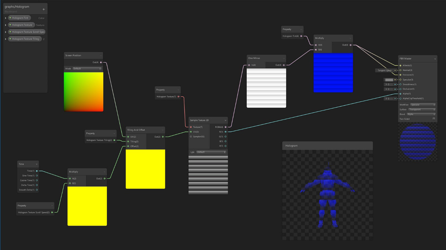
Figure 6.14 Shader Graph with nodes to create a custom effect
We will discuss later what those nodes do and will do a step-by-step effect example, but in the screenshot, you can see how the author created and connected several nodes, which are those interconnected boxes, each one doing a specific process to achieve the effect. The idea of creating effects with Shader Graph is to learn which specific nodes you need and how to connect them properly, to create an "algorithm" or a series of ordered steps to achieve a specific result. This is similar to the way we code the gameplay of the game, but this Graph is adapted and simplified just for effect purposes.
To create and edit our first Shader Graph asset, do the following:
- In the Project Window, click the + icon and find the Shader | PBR Graph option. This will create a Shader Graph using PBR mode, meaning that this Shader will support lighting effects (unlike Unlit Graphs):

Figure 6.15 PBR Shader Graph creation
- Name it WaterGraph. If you lose the opportunity to rename the asset, remember that you can select the asset, right-click, and select Rename:
Figure 6.16 Shader Graph Asset
- Create a new Material called WaterMaterial and set Shader to Shader Graphs/Water. If for some reason Unity doesn't allow you to do that, try right-clicking WaterGraph and clicking Reimport. As you can see, the created Shader Graph asset now appears as a Shader in the Material, meaning that we have already created a custom Shader:
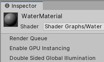
Figure 6.17 Setting a Shader Graph as a Material Shader
- Create a Plane with the GameObject | 3d Object | Plane option.
- Drag the Material to the Plane to apply it.
Now, you have created your first custom Shader and applied it to a Material. So far, it doesn't look interesting at all—it's just a gray effect, but now it's time to edit the graph to unlock its full potential. As the name of the Graph suggests, we will be creating a water effect in this chapter to illustrate several nodes of the Shader Graph toolset and how to connect them, so let's start by discussing the Master node. When you open the graph by double-clicking it, you will see the following:
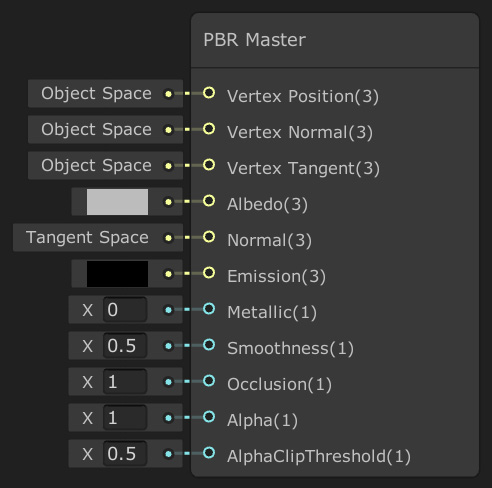
Figure 6.18 Master node with all of the properties needed to calculate object appearance
All nodes will have input pins, the data they need to work, and output pins, which are the results of its process. As an example, in a sum operation, we will have two input numbers and an output number, the result of the sum. In this case, you can see that the Master node just has inputs, and that's because all data that enters the Master node will be used by Unity to calculate the Rendering and Lighting of the object, things such as the desired object color or texture (the Albedo input pin), how smooth it is (the Smoothness input pin), or how much metal it contains (the Metallic input pin), so they are all of the properties that will affect how the lighting will be applied to the object. In a sense, the input of this node is the output data of the entire graph and the ones we need to fill.
Let's start exploring how we can change that output data by doing the following:
- Double-click Shader Graph to open its editor window.
- Click in the gray rectangle to the left of the Albedo input pin:

Figure 6.19 Albedo Master node input pin
- In the color picker, select a light blue color, like water. Select the bluish part of the circle around the picker and then a shade of that color in the middle rectangle:
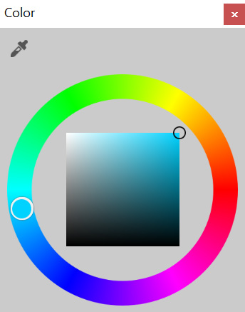
Figure 6.20 Color picker
- Set Smoothness to 0.9:
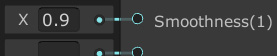
Figure 6.21 Smoothness PBR Master node input pin
- Click the Save Asset button at the top-left of the window:
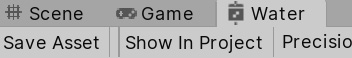
Figure 6.22 Shader Graph saving options
- Go back to the Scene View and check the plane is light blue and with the sun reflected on it:
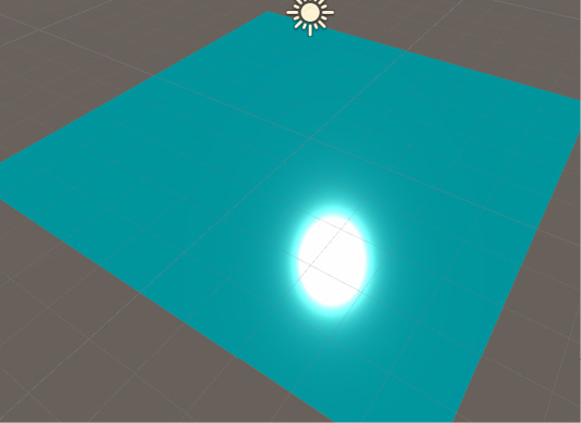
Figure 6.23 Initial Shader Graph results
As you can see, the behavior of the Shader varies according to the properties you set in the Master node, but so far, doing this is no different than creating an Unlit Shader and setting up its properties; the real power of Shader Graph is when you use nodes that do specific calculations as inputs of the Master node. We will start seeing the texturing nodes, which allow us to apply Textures to our model.
Using Textures
The idea of using Textures is to have an image applied to the model in a way that means we can paint different parts of the model with different colors. Remember that the model has the UV map, which allows Unity to know which part of the Texture will be applied to which part of the model:
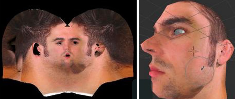
Figure 6.24 On the left, a face texture; on the right, the same texture applied to a face mesh
We have several nodes to do this task, one of them being Sample Texture 2D, a node that has two main inputs. First, it asks us for the texture to sample or apply to the model and then the UV. You can see it in the following screenshot:
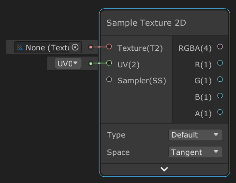
Figure 6.25 Sample Texture node
As you can see, the default value of the Texture input node is None, so there's no texture by default, and we need to manually specify that. For UV, the default value is UV0, meaning that, by default, the node will use the main UV channel of the model, and yes, a model can have several UVs set, but for now, we will stick with the main one. Let's try this node, doing the following:
- Download and import a Tileable Water Texture from the internet:
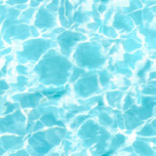
Figure 6.26 Water tileable Texture
- Select the Texture and be sure that the Wrap Mode property of the Texture is on Repeat, which will allow us to repeat the Texture as we did in the terrain, because the idea is to use this Shader to cover large water areas:

Figure 6.27 Texture Repeat mode
- In the Water Shader Graph, right-click in an empty area of the Shader Graph and select Create Node:
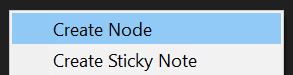
Figure 6.28 Shader Graph Create Node option
- In the Search box, write Sample texture and all of the sample nodes will show up. Select Sample Texture 2D double clicking it:
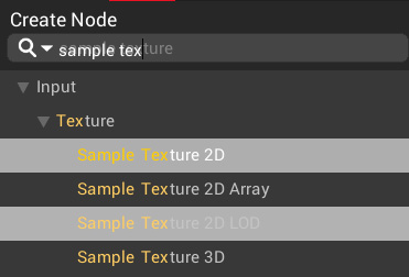
Figure 6.29 Sample texture node search
- Click in the circle to the left of the Texture input pin of the Sample Texture 2D node. It will allow us to pick a Texture to sample—just select the water one. You can see that the Texture can be previewed in the bottom part of the node:
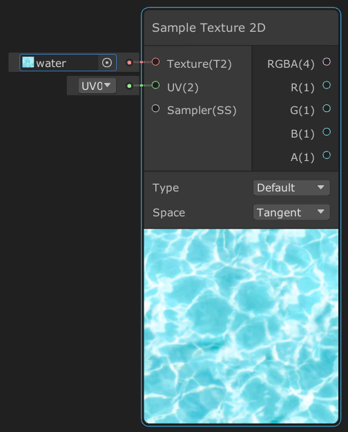
Figure 6.30 Sample Texture node with a Texture in its input pin
- Drag the output pin RGBA from the Sample Texture 2D node to the Albedo input pin of the Master node:
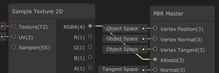
Figure 6.31 Connecting the results of a Texture sampling with the Albedo pin of the Master node
- Click the Save Asset button at the top-left part of the Shader Graph editor and see the changes in the scene view:
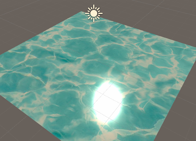
Figure 6.32 Results of applying a Texture in our Shader Graph
As you can see, the texture is properly applied to the model, but if you take into account that the default plane has a size of 10x10 meters, the ripples of the water seem too big, so let's tile the Texture! To do that, we need to change the UVs of the model, making them bigger. Bigger UVs sounds like the Texture should also get bigger, but take into account that we are not making the object bigger; we are just modifying the UV, so the same object size will read more of the texture, meaning that the bigger texture sample area will make repetitions of the texture and put them in the same object size, so that will be compressed inside the model area. To do so, follow the next steps:
- Right-click in any empty space area and click New Node to search the UV node:
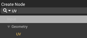
Figure 6.33 Searching for the UV node
- Using the same method create a Multiply node.
- Set the B pin input value to (4,4,4,4):
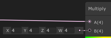
Figure 6.34 Multiplying the UVs by 4
- Drag the Out pin of the UV node to the A pin of the Multiply node to connect them.
- Drag the Out pin of the Multiply node to the UV pin of the Sample Texture 2D node to connect them:
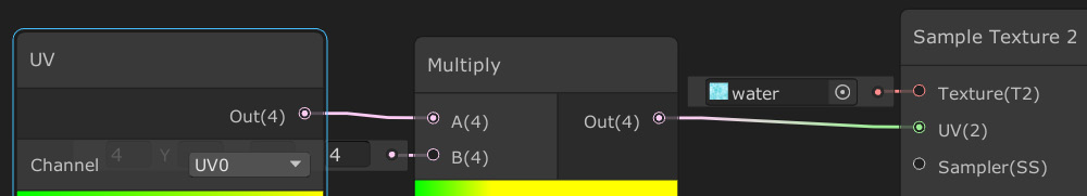
Figure 6.35 Using the multiplied UVs to sample the Texture
- If you save the graph and go back to the Scene View, you can see that now the ripples are smaller, because we have tiled the UVs of our model. You can also see that in the preview of the Sampler Texture 2D node:
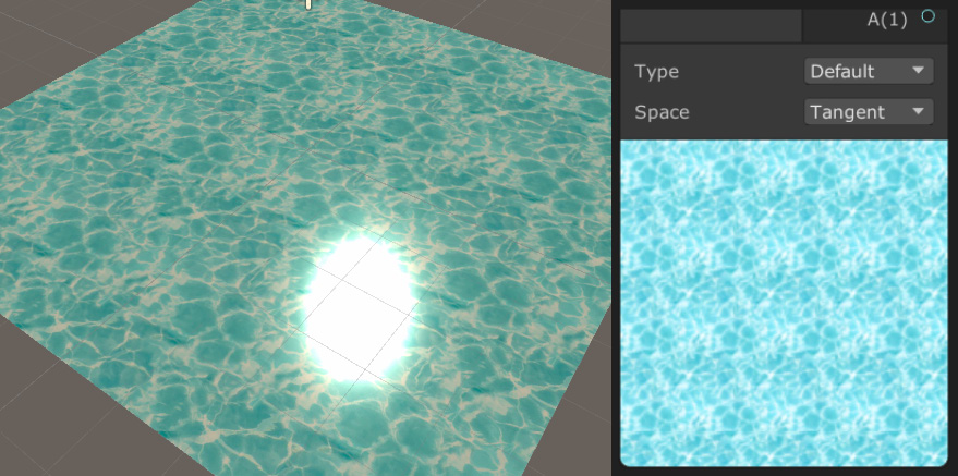
Figure 6.36 Results of the model's UV multiplication
Another interesting effect we can do now is to apply an Offset to the Texture to move it. The idea is that even if the plane is not actually moving, we will simulate the flow of the water through it, moving just the Texture. Remember, the responsibility of determining the part of the Texture to apply to each part of the model belongs to the UV, so if we add values to the UV coordinates, we will be moving them, generating a Texture sliding effect. To do so, let's do the following:
- Create an Add node to the right of the Multiply node.
- Connect the Out pin of the UV to the A pin of the Add node:
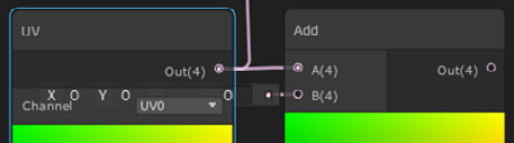
Figure 6.37 Adding values to the UVs
- Create a Time node at the left of the Add node.
- Connect the Time node to the B pin of the Add node:
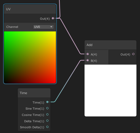
Figure 6.38 Adding time to the UVs
- Connect the Out pin of the Add node to the A input pin of the Multiply node:
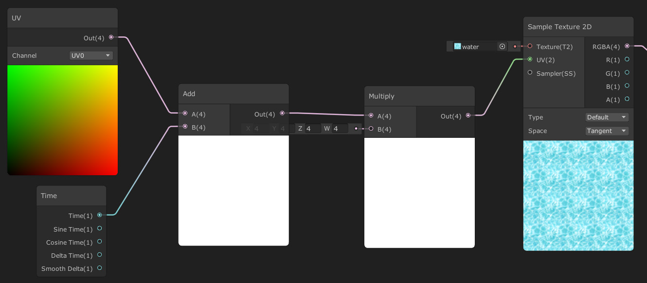
Figure 6.39 Added and multiplied UVs as an input of the Sample Texture
- Save and see the water moving in the Scene View.
- If you feel the water is moving too fast, try to use the multiplication node to make the time a smaller value. I recommend you try it by yourself before looking at the next screenshot, which has the answer:
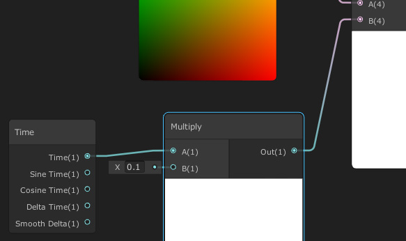
Figure 6.40 Multiplication of time to move it faster
- If you feel the graph is starting to get bigger, try to hide some of the node previews by clicking on the up arrow that appears on the preview when you move the mouse over it:
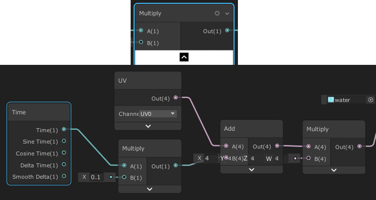
Figure 6.41 Hiding the preview and unused pins from the graph nodes
So, to recap, first we added the time to the UV to move it and then multiplied the result of the moved UV to make it bigger to tile the Texture. It is worth mentioning that there's a Tiling and Offset node that does all of this for us, but I wanted to show you how a simple multiplication to scale the UV and an add operation to move it generated a nice effect; you can't imagine all of the possible effects you can achieve with other simple mathematical nodes! Actually, let's explore other usages of mathematical nodes to combine Textures in the next section.
Combining Textures
Even though we have used nodes, we haven't created anything that can't be created using regular Shaders, but that's about to change. So far, we can see the water moving but it still look static, and that's because the ripples are always the same. We have several techniques to generate ripples, and the simplest one would be to combine two water Textures moving in different directions to mix their ripples, and actually, we can simply use the same Texture, just flipped, to save some memory. To combine the Textures, we will sum them and then divide them by 2, so basically, we are calculating the average of the textures! Let's do that by doing the following:
- Select all of the nodes between Time and Sampler 2D (including them), creating a selection rectangle by clicking in any empty space in the graph, holding and dragging the click, and then releasing when all target nodes are covered:
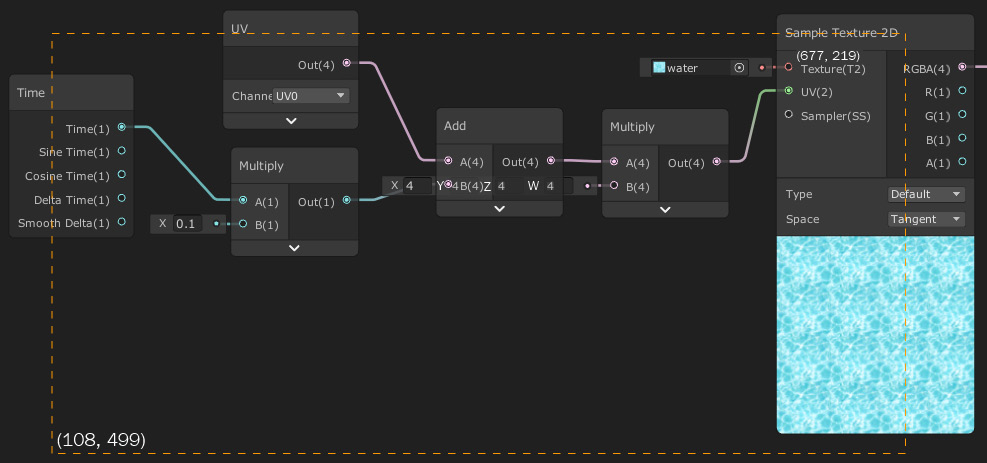
Figure 6.42 Selecting several nodes
- Right-click and select Copy, and then again right-click and select Paste, or use the classic Ctrl + C, Ctrl + V commands (command + C, command + V in Mac), or just Ctrl + D (command + D).
- Move the copied nodes below the original ones:
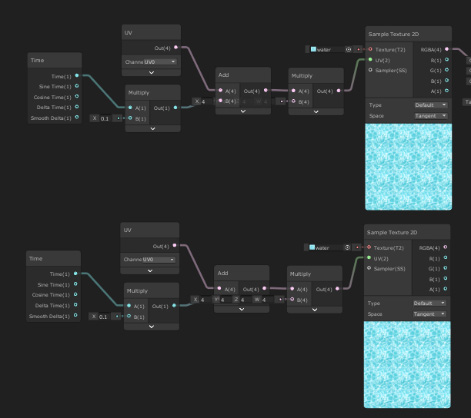
Figure 6.43 Duplication of nodes
- For the copied nodes, set the B pin of the Multiply node connected to the Sample Texture 2D to (-4,-4,-4,-4). You can see that that flipped the texture.
- Also, set the B pin of the Multiply node connected to the Time node in -0.1:
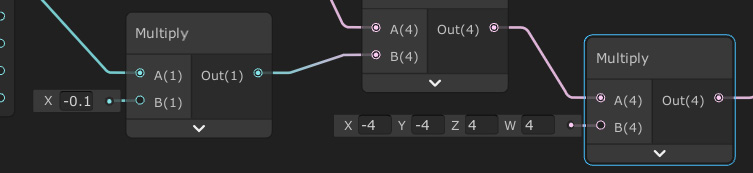
Figure 6.44 Multiplication of values
- Create an Add node at the right of both Sampler Texture 2D nodes and connect the outputs of those nodes as the A and B input pins of the Add node:
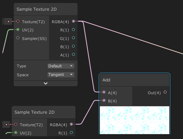
Figure 6.45 Adding two Textures
- You can see that the resulting combination is too bright because we have summed up the intensity of both textures, so let's fix that by multiplying the Out of the Add node by (0.5,0.5,0.5,0.5), which will divide each resulting color channel by 2, averaging the color:
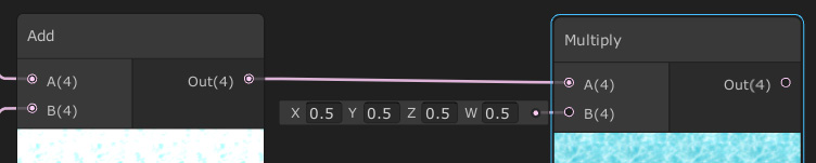
Figure 6.46 Dividing the sum of two Textures to get the average
- Connect the Out pin of the Multiply node to the Albedo pin of the Master node to apply all of those calculations as the color of the object.
- Save the Asset and see the results in the Scene View:
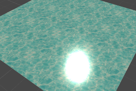
Figure 6.47 Results of texture blending
You can keep adding nodes to make the effect more diverse, such as using Sinus nodes to apply non-linear movements and so on, but I will let you learn that by experimenting with this by yourself. For now, we will stop here. As always, this topic deserves a full book, and the intention of this chapter is to give you a small taste of this powerful Unity tool. I recommend you look for other Shader Graphs examples on the internet to learn other usages of the same nodes and, of course, new nodes. One thing to consider here is that everything we just did is basically applied to the Fragment Shader stage of the Shader Pipeline we discussed earlier. Now, let's use the Blending Shader stage to apply some transparency to the water.
Applying transparency
Before declaring our effect finished, a little addition we can do is to make the water a little bit transparent. Remember that the Shader Pipeline has this Blending stage, which has the responsibility of blending each pixel of our model into the image being rendered in this frame. The idea is to make our Shader Graph modify that stage to apply an Alpha Blending, a blending that combines our model and the previous rendered models based on the Alpha value of our model. To get that effect, do the following steps:
- Click the wheel at the top-right part of the Master node.
- Set Surface property to Transparent.
- Set the Blend property to Alpha if it isn't already at that value:
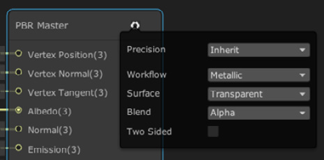
Figure 6.48 PBR Master node settings
- Set the Alpha input pin of the Master to 0.5:
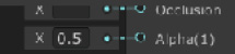
Figure 6.49 Setting the Alpha of the Master node
- Save the graph and see the transparency being applied in the Scene View. If you can't see the effect, just put a cube in the water to make the effect more evident:
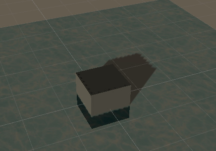
Figure 6.50 Shadows from the water being applied to a cube
- You can see the shadows that the water is casting on our cube. That's because Unity doesn't detect that the object is transparent, so it thinks that it must cast shadows, so let's disable them. Click on the water plane and look for the Mesh Renderer component in the Inspector.
- In the Lighting section, set Cast Shadows to Off; this will disable shadow casting from the Plane:
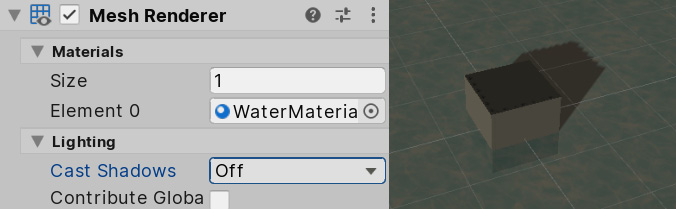
Figure 6.51 Disabling shadow casting
Adding transparency is a simple process but has its caveats, such as the shadow problem, and in more complex scenarios, it can have other problems, so I would suggest that you avoid using transparency unless it is necessary. Actually, our water can live without transparency, especially when we apply this water to the river basin around the base, because we don't need to see what's under the water, but the idea is for you to know all of your options. In the next screenshot, you can see how we have put a giant plane with this effect below our base, big enough to cover the entire basin:
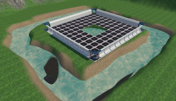
Figure 6.52 Using our water in the main scene
Summary
In this chapter, we discussed how a Shader works using a GPU and how to create our first simple Shader to achieve a nice water effect. Using Shaders is a complex and interesting job, and in a team, there are usually one or more people in charge of creating all of these effects, in a position called technical artist; so, as you can see, this topic can expand up to become a whole career. Remember, the intention of this book is to give you a small taste of all the possible roles you can take in the industry, so if you really liked this role, I suggest you start reading Shader-exclusive books. You have a long but super-interesting road in front of you.
But enough Shaders, for now—let's move to the next topic about improving graphics and creating visual effects with particle systems!