
Chapter 8: Lighting Using the Universal Render Pipeline
Lighting is a complex topic and there are several possible ways to handle it, with each one having its pros and cons. In order to get the best possible quality at the best performance, you need to know exactly how your renderer handles it, and that is exactly what we are going to do in this chapter. We will discuss how lighting is handled in Unity's Universal Render Pipeline (URP), as well as how to properly configure it to adapt our scene's mood with proper lighting effects.
In this chapter, we will examine the following lighting concepts:
- Applying lighting
- Applying shadows
- Optimizing lighting
Applying lighting
When discussing ways to process lighting in a game, there are two main ways we can do so, known as Forward Rendering and Deferred Rendering. Both handle lighting in a different order, with different techniques, requirements, pros, and cons. Forward Rendering is usually recommended for performance, while Deferred Rendering is usually recommended for quality. The latter is used by the High Definition Render Pipeline of Unity, the renderer used for high-quality graphics in high-end devices. At the time of writing this book, Unity is developing a performant version for URP. Also, in Unity, Forward Renderer comes in two flavors: Multi-Pass Forward, which is used in the built-in renderer (the old Unity renderer), and Single Pass Forward, which is used in URP. Again, each has its pros and cons.
Important information
Actually, there are other options available, both official and third-party, such as Vertex Lit, but for now, we will focus on the three main ones – the ones you use 95% of the time.
Choosing between one or another depends on the kind of game you are creating and the target platform you need to run the game on. Your chosen option will change a lot due to the way you apply lighting to your scene, so it's crucial you understand which system you are dealing with.
In this section, we will discuss the following Realtime lighting concepts:
- Discussing lighting methods
- Configuring ambient lighting with skyboxes
- Configuring lighting in URP
Let's start by comparing the previously mentioned lighting methods.
Discussing lighting methods
To recap, we mentioned three main ways of processing lighting:
- Forward Rendering (Single Pass)
- Forward Rendering (Multi-Pass)
- Deferred Rendering
Before we look at the differences between each, let's talk about the things they have in common. Those three renderers start drawing the scene by determining which objects can be seen by the camera; that is, the ones that fall inside the camera's frustum, and provide a giant pyramid that can be seen when you select the camera:
Figure 8.1 – The camera's frustum showing only the objects that can be seen by it
After that, Unity will order them from the nearest to the camera to the farthest (transparent objects are handled a little bit differently, but let's ignore that for now). It's done like this because it's more probable that objects nearer to the camera will cover most of the camera, so they will occlude others, preventing us from wasting resources calculating pixels for the occluded ones.
Finally, Unity will try to render the objects in that order. This is where differences start to arise between lighting methods, so let's start comparing the two Forward Rendering variants. For each object, Single Pass Forward Rendering will calculate the object´s appearance, including all the lights that are affecting the object, in one shot, or what we call a Draw Call. A Draw Call is the exact moment when Unity asks the video card to actually render the specified object. All the previous work was just preparation for this moment. In the case of the Multi-Pass Forward Renderer, by simplifying a little bit of the actual logic, Unity will render the object once per light that affects the object. So, if the object is being lit by three lights, Unity will render the object three times, meaning that three Draw Calls will be issued, and three calls to the GPU will be made to execute the rendering process:
.jpg)
Figure 8.2 – Left image, first draw call of a sphere affected by two lights in Multi-Pass; middle image, second draw call of the sphere; right image, the combination of both Draw Calls
Now is when you are probably thinking, "Why should I use Multi-Pass? Single-Pass is more performant!" And yes, you are right! Single-Pass is way more performant than Multi-Pass, and here comes the great bit. A Draw Call in a GPU has a limited amount of operations that can be executed, so you have a limit to the complexity of the Draw Call. Calculating the appearance of an object and all the lights that affect it is very complex, and in order to make it fit in just one Draw Call, Single Pass executes simplified versions of lighting calculations, meaning less lighting quality and features. They also have a limit on how many lights can be handled in one shot, which, at the time of writing this book, is eight per object (four for low-end devices). This sounds like a small number, but it's usually just enough.
On the other side, Multi-Pass can apply any number of lights you want and can execute different logic for each light. Let's say our object has four lights that are affecting it, but there are two lights that are affecting it drastically because they are nearer or have higher intensity, while the remaining ones affecting the object are just enough to be noticeable. In this scenario, we can render the first two lights with higher quality and the remaining ones with cheap calculations – no one will be able to tell the difference. In this case, Multi-Pass can calculate the first two lights using Pixel Lighting and the remaining ones using Vertex Lighting. The difference is in their names; Pixel calculates light per object's pixel, while Vertex calculates light per object vertex and fills the pixels between these vertexes, thereby interpolating information between vertexes. You can clearly see the difference in the following images:
.jpg)
Figure 8.3 – Left image, a sphere being rendered with Vertex Lighting; right image, a sphere being rendered with Pixel Lighting)
In Single Pass, calculating everything in a single draw call forces you to use Vertex Lighting or Pixel Lighting; you cannot combine them.
So, to summarize the differences between Single and Multi-Pass, in Single Pass, you have better performance because each object is just drawn once, but you are limited to the number of lights that can be applied, while in Multi-Pass, you need to render the object several times, but with no limits on the number of lights, and you can specify the exact quality you want for each light. There are other things to consider, such as the actual cost of a Draw Call (one Draw Call can be more expensive than two simple ones), and special lighting effects such as toon shading, but let's keep things simple.
Finally, let's briefly discuss Deferred. Even though we are not going to use it, it's interesting to know why we are not doing that. After determining which objects fall inside the frustum and ordering them, Deferred will render the objects without any lighting, generating what is called a G-Buffer. A G-Buffer is a set of several images that contain different information about the objects of the scene, such as the colors of its pixels (without lighting), the direction of each pixel (known as Normals), and how far from the camera the pixels are. You can see a typical example of a G-Buffer in the following figure:
.jpg)
Figure 8.4 – Left image, plain colors of the object; middle image, depths of each pixel; right image, normals of the pixels
Important information
Normals are directions, and the (X,Y,Z) components of the directions are encoded in the RGB components of the colors.
After rendering all the objects in the scene, Unity will iterate over all lights that can be seen in the camera, thus applying a layer of lighting over the G-Buffer, taking information from it to calculate that specific light. After all the lights have been processed, you will get the following result:
Figure 8.5 – Combination of the three lights that were applied to the G-Buffer shown in the previous image
As you can see, the Deferred part of this method comes from the idea of calculating lighting as the last stage of the rendering process. This is better because you won't waste resources calculating lighting from objects that could potentially be occluded. If the floor of the image is being rendered first in Forward, the pixels that the rest of the objects are going to occlude were calculated in vain. Also, there's the detail that Deferred just calculates lighting in the exact pixels that the light can reach. As an example, if you are using a flashlight, Unity will calculate lighting only in the pixels that fall inside the cone of the flashlight. The con here is that Deferred is not supported by some relatively old video cards and that you can't calculate lighting with Vertex Lighting quality, so you will need to pay the price of Pixel Lighting, which is not recommended on low-end devices (or even necessary in simple graphics games).
So, why are we using URP with Single Pass Forward? Because it offers the best balance between performance, quality, and simplicity. In this game, we won't be using too many lights, so we won't worry about the light number limitations of Single Pass, and we won't take advantage of the Deferred benefits too much, so it makes no sense to use more hardware to run the game.
Now that we have a very basic notion of how URP handles lighting, let's start using it!
Configuring ambient lighting with skyboxes
There are different light sources that can affect the scene, such as the sun, torches, light bulbs, and more. Those are known as Direct Lights; that is, objects that emit light rays. Then, we have Indirect Light, light that usually represents bounces of Direct Lights. However calculating all the bounces of all the rays emitted by all the lights is impossible if you want to get a game running at least 30 FPS (or simply running). The problem is that not having Indirect Light will generate unrealistic results since our current scene lighting, where you can observe places where the sunlight doesn't reach, is completely dark because no light is bouncing from other places where light hits:

Figure 8.6 – Shadows projected on a mountain without ambient lighting
To solve this problem, we can use approximations of those bounces. These are what we call ambient light. This represents a base layer of lighting that usually applies a little bit of light based on the color of the sky, but you can choose whatever color you want. As an example, on a clear night, we can pick a dark blue color to represent the tint from the moonlight.
By default, Unity won't calculate ambient light from the sky, so we need to manually do that doing the following:
- Select the Terrain in the Hierarchy and uncheck Static at the top right part of the Inspector. Later we will explain why we did this:

Figure 8.7 – Terrain in Hierarchy
- Click on Window | Rendering | Lighting Settings. This will open the Scene Lighting Settings window:
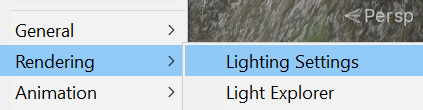
Figure 8.8 – Lighting Settings location
- Click the Generate Lighting button at the bottom of the window. If you haven't saved the scene so far, a prompt will ask you to save it, which is necessary:

Figure 8.9 – Generate Lighting button
- See the bottom-right part of the Unity window to check the progress calculation bar to check when the process has finished:

Figure 8.10 – Lighting generation progress bar
- You can now see how completely dark areas now have a little effect shown on them from the light being emitted by the sky:
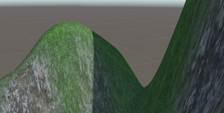
Figure 8.11 – Shadows with ambient lighting
Now, by doing this, we have better lighting, but it still looks like a sunny day. Remember, we want to have rainy weather. In order to do that, we need to change the default sky so that it's cloudy. You can do that by downloading a skybox. The current sky you can see around the scene is just a big cube containing textures on each side, and those have a special projection to prevent us from detecting the edges of the cube. We can download six images for each side of the cube and apply them to have whatever sky we want, so let's do that:
- You can download skybox textures from wherever you want, but here, I will choose the Asset Store. Open it by going to Window | Asset Store and going to the Asset Store website.
- Look for 2D | Textures & Materials | Sky in the category list on the right. Remember that you need to make that window wider if you can't see the category list:

Figure 8.12 – Skybox category
- Remember to check the Free Assets checkbox in the Pricing section:

Figure 8.13 – Free Assets filtering
- Pick any skybox you like for a rainy day. Take into account that there are different formats for skyboxes. We are using the six-image format, so check that before downloading one. In my case, I have chosen the skybox pack shown in the following figure. Download and import it, as we did in Chapter 5, Importing and Integrating Assets:
Figure 8.14 –Selected skybox set for this book
- Create a new material by using the + icon in the Project window and selecting Material.
- Set the Shader option of that material to Skybox/6 sided. Remember that the skybox is just a cube, so we can apply a material to change how it looks. The skybox shader is prepared to apply the six textures.
- Drag the six textures to the Front, Back, Left, Right, Up, and Down properties of the material. The six downloaded textures will have descriptive names so that you know which textures go where:

Figure 8.15 – Skybox material settings
- Drag the material directly into the sky in the Scene View. Be sure you don't drag the material into an object because the material will be applied to it.
- Repeat steps 1 to 4 of the ambient light calculation (Lighting Settings | Generate Lighting) to recalculate it based on the new skybox. In the following figure, you can see the result of my project so far:
Figure 8.16 – Applied skybox
Now that we have a good base layer of lighting, we can start adding light objects.
Configuring lighting in URP
We have three main types of Direct Lights we can add to our scene:
- Directional Light: This is a light that represents the sun. This object emits light rays in the direction it is facing, regardless of its position; the sun moving 100 meters to the right won't make a big difference. As an example, if you slowly rotate this object, you can generate a day/night cycle:
.jpg)
Figure 8.17 – Directional Light results
- Point Light: This light represents a light bulb, which emits rays in an omnidirectional way. The difference it has on the sun is that its position matters because it's closer. Also, because it's a weaker light, the intensity of this light varies according to the distance, so its effect has a range – the further the object from the light, the weaker the received intensity:
.jpg)
Figure 8.18 – Point Light results
- Spotlight: This kind of light represents a light cone, such as the one emitted by a flashlight. It behaves similarly to point lights in that its position and direction matters, and the light intensity decays over a certain distance:
.jpg)
Figure 8.19 – Spotlight results
So far, we have a nice, rainy, ambient lighting, but the only Direct Light we have in the scene, the Directional Light, won't look like this, so let's change that:
- Select the Directional Light object in the Hierarchy window and then look at the Inspector window.
- Click the Colour property to open the Color Picker.
- Select a dark gray color to achieve sun rays partially occluded by clouds.
- Set Shadow Type to No Shadows. Now that we have a cloudy day, the sun does not project clear shadows, but we will talk more about shadows in a moment:
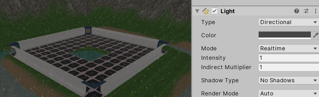
Figure 8.20 – Soft directional light with no shadows
Now that the scene is darker, we can add some lights to light up the scene, as follows:
- Create a Spotlight by going to GameObject | Light | Spotlight:

Figure 8.21 – Creating a Spotlight
- Select it. Then, in the Inspector window, set Inner/Output Spot Angle to 90 and 120, which will increase the angle of the cone.
- Set Range to 50, meaning that the light can reach up to 50 meters, decaying along the way.
- Set Intensity to 1000:

Figure 8.22 – Spotlight settings
- Position the light at one corner of the base, pointing it at the center:
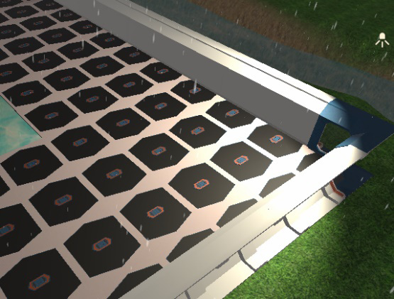
Figure 8.23 – Spotlight placement
- Duplicate that light by selecting it and pressing Ctrl + D (command + D on Mac).
- Put it in the opposite corner of the base:

Figure 8.24 –Two Spotlight results
You can keep adding lights to the scene but take care that you don't go too far – remember the light limits. Also, you can download some light posts to put in where the lights are located to visually justify the origin of the light. Now that we have achieved proper lighting, we can talk about shadows.
Applying shadows
Maybe you are thinking that we already have shadows in the scene, but actually, we don't. The darker areas of the object, the ones that are not facing the lights, don't have shadows – they are not being lit, and that's quite different from a shadow. In this case, we are referring to the shadows that are projected from one object to another; for example, the shadow of the player being projected on the floor, or from the mountains to other objects. Shadows can increase the quality of our scene, but they also cost a lot to calculate, so we have two options: not using shadows (recommended for low-end devices such as mobiles) or finding a balance between performance and quality according to our game and the target device. In the first case, you can skip this whole section, but if you want to achieve performant shadows (as much as possible), keep reading.
In this section, we are going to discuss the following topics about shadows:
- Understanding shadow calculations
- Configuring performant shadows
Let's start by discussing how Unity calculates shadows.
Understanding shadow calculations
In game development, it is well-known that shadows are costly in terms of performance, but why? An object has a shadow when a light ray hits another object before reaching it. In that case, no lighting is applied to that pixel from that light. The problem here is the same problem we have with the light that ambient lighting simulates – it would be too costly to calculate all possible rays and its collisions. So, again, we need an approximation, and here is where Shadow Maps kick in.
A Shadow Map is an image that's rendered from the point of view of the light, but instead of drawing the full scene with all the color and lighting calculations, it will render all the objects in grayscale, where black means that the pixel is very far from the camera and whiter means that the pixel is nearer to the camera. If you think about it, each pixel contains information about where a ray of the light hits. By knowing the position and orientation of the light, you can calculate the position where each "ray" hit using the Shadow Map. In the following figure, you can see the Shadow Map of our Directional Light:

Figure 8.25 – Shadow Map generated by the Directional Light of our scene
Each type of light calculates Shadow Maps slightly differently, especially the Point Light. Since it's omnidirectional, it needs to render the scene several times in all its directions (front, back, up, down, right, and left) in order to gather information about all the rays it emits. We won't talk about this in detail here, though, as we could talk about it all day.
Now, something important to highlight here is that Shadow Maps are textures, and hence they have a resolution. The higher the resolution, the more "rays" our Shadow Map calculates. You are probably wondering what a low-resolution shadow map looks like when it has only a few rays in it. Take a look at the following figure to see one:
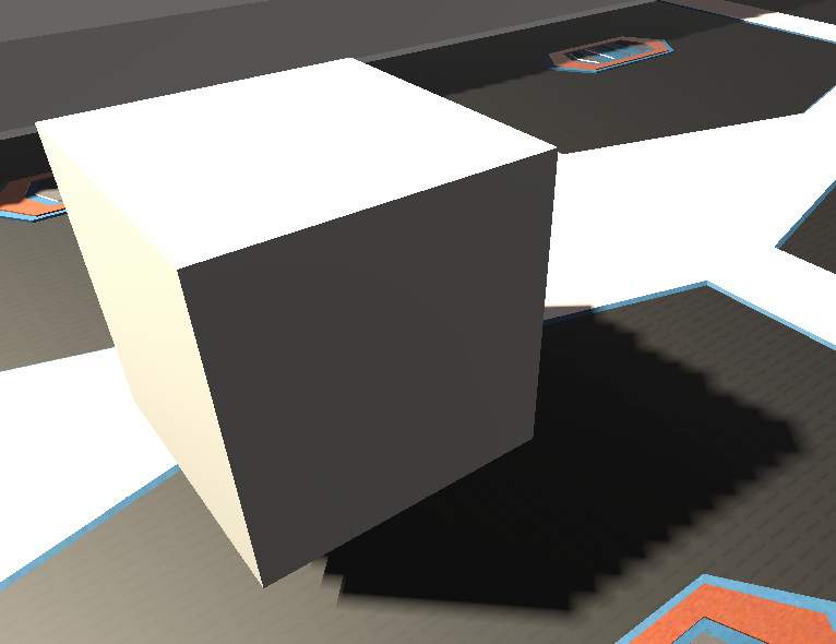
Figure 8.26 – Hard Shadow rendered with a low-resolution Shadow Map
The problem here is that having fewer rays generates bigger shadow pixels, resulting in a pixelated shadow. Here, we have our first configuration to consider: what is the ideal resolution for our shadows? You will be tempted to just increase it until the shadows look smooth, but of course, that will increase how long it will take to calculate it, so it will impact the performance considerably unless your target platform can handle it (mobiles definitely can't). Here, we can use the Soft Shadows trick, where we can apply a blurring effect over the shadows to hide the pixelated edges, as shown in the following figure:

Figure 8.27 – Soft Shadows rendered with a low-resolution Shadow Map
Of course, the blurry effect is not free, but combining it with low-resolution shadow maps, if you accept its blurry result, can generate a nice balance between quality and performance.
Now, low-resolution Shadow Maps have another problem, which is called Shadow Acne. This is the lighting error you can see in the following figure:

Figure 8.28 – Shadow Acne from a low-resolution Shadow Map
A low-resolution shadow map generates false positives because it has fewer "rays" calculated. The pixels to be shaded between the rays need to interpolate information from the nearest ones. The lower the Shadow Map's resolution, the larger the gap between the rays, which means less precision and more false positives. One solution would be to increase the resolution, but again, there will be performance issues (as always). We have some clever solutions to this, such as using depth bias. An example of this can be seen in the following figure:

Figure 8.29 – A false positive between two far "rays." The highlighted area thinks the ray hit an object before reaching it.
The concept of depth bias is simple – so simple that it seems like a big cheat, and actually, it is, but game development is full of them! To prevent false positives, we "push" the rays a little bit further, just enough to make the interpolated rays reach the hitting surface:
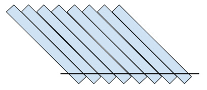
Figure 8.30 – Rays with a depth bias to eliminate false positives
Of course, as you are probably expecting, they don't solve this problem easily without having a caveat. Pushing depth generates false negatives in other areas, as shown in the following figure. It looks like the cube is floating, but actually, it is touching the ground – the false negatives generate the illusion that it is floating:
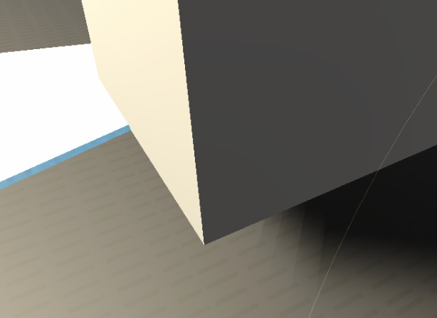
Figure 8.31 – False negatives due to a high depth bias
Of course, we have a counter trick to this situation known as normal bias. It still pushes objects, but along the direction they are facing. This one is a little bit tricky, so we won't go into too much detail here, but the idea is that combining a little bit of depth bias and another bit of normal bias will reduce the false positives, but not completely eliminate them. Therefore, we need to learn how to live with that and hide it by cleverly positioning objects:

Figure 8.32 – Reduced false negatives, which is the result of combining depth and normal bias
There are several other aspects that affect how Shadow Map works, with one of them being the light range. The smaller the light range, the less area the shadows will cover. The same Shadow Map resolution can add more detail to that area, so try to reduce the light ranges as much as you can.
I can imagine your face right now, and yes, lighting is complicated, and we've only just scratched the surface! But keep your spirits up! After a little trial and error fiddling with the settings, you will understand it better. We'll do that in the next section.
Important information
If you are really interested in learning more about the internals of the shadow system, I recommend that you look at the concept of Shadow Cascades, an advanced topic about Directional Lights and Shadow Map generation.
Configuring performant shadows
Because we are targeting mid-end devices, we will try to achieve a good balance of quality and performance here, so let's start enabling shadows just for the spotlights. The Directional Light shadow won't be that noticeable, and actually, a rainy sky doesn't generate clear shadows, so we will use that as an excuse to not calculate those shadows. In order to do this, do the following:
- Select both Point Lights by clicking them in the Hierarchy while pressing Ctrl (Command on Mac). This will ensure that any changes made in the Inspector window will be applied to both:
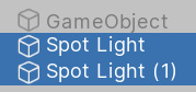
Figure 8.33 – Selecting multiple objects
- In the Inspector window, set Shadow Type to Soft Shadows. We will be using low-resolution shadow maps here:

Figure 8.34 – Soft Shadows setting
- Select Directional light and set Shadow Type to No Shadows to prevent it from casting shadows:

Figure 8.35 – No Shadows setting
- Create a cube (GameObject | 3D Object | Cube) and place it near one of the lights, just to have an object that we can cast shadows on for testing purposes.
Now that we have a base test scenario, let's fiddle with the Shadow Maps resolution settings, preventing Shadow Acne in the process:
- Go to Edit | Project Settings.
- In the left-hand side list, look for Graphics and click it:

Figure 8.36 – Graphics settings
In the properties that appear after selecting this option, click in the box below Scriptable Render Pipeline Settings – the one that contains a name. In my case, this is LWRP-HighQuality, but yours may be different due to you having a different version of Unity:

Figure 8.37 – Current Render Pipeline setting
- Doing that will highlight an asset in the Project window, so be sure that window is visible before selecting it. Select the highlighted asset:
Figure 8.38 – Current pipeline highlighted
- This asset has several graphics settings related to how URP will handle its rendering, including lighting and shadows. Expand the Lighting section to reveal its settings:

Figure 8.39 – Pipeline lighting settings
- The Shadow Resolution setting under the Additional Lights subsection represents the Shadow Map resolution for all the lights that aren't the Directional Light (since it's the Main Light). Set it to 1024 if it's not already at that value.
- Under the Shadows section, you can see the Depth and Normal Bias settings, but those only work for the Directional Light. So, instead, select both spotlights, set Bias mode to custom, and set the Depth and Normal Bias to 0.25 in order to reduce them as much as we can before we remove the Shadow Acne:

Figure 8.40 – Light shadows settings
- This isn't entirely related to shadows, but here, you can change the Per Object Light limit to increase or reduce the number of lights that can affect the object (no more than eight).
- In case you followed the shadow cascades tip presented earlier, you can play with the Cascades value a little bit to enable shadows for Directional Light to notice the effect. Remember that those shadow settings only work for Directional Light.
- Set both lights so that they have a 40-meter range. See how the shadows improve in quality before and after the change:
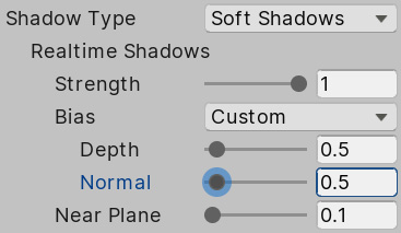
Figure 8.41 – Bias settings
Remember that those values only work in my case, so try to fiddle with the values a little bit to see how that changes the result – you may find a better setup for your PC. Also, remember that not having shadows is always an option, so always consider that in case your game is running low on FPS (and there isn't another performance problem lurking).
You probably think that that is all we can do about performance in terms of lighting, but luckily, that's not the case! We have another resource we can use to improve it further known as static lighting.
Optimizing lighting
We mentioned previously that not calculating lighting is good for performance, but what about not calculating lights, but still having them? Yes, its sounds too good to be true, but it is actually possible (and, of course, tricky). We can use a technique called static lighting or baking, which allows us to calculate lighting once and use the cached result.
In this section, we will cover the following concepts related to Static Lighting:
- Understanding static lighting
- Baking lightmaps
- Applying static lighting to dynamic objects
Understanding static lighting
The idea is pretty simple: just do the lighting calculations once, save the results, and then use those instead of calculating lighting all the time. You may be wondering why this isn't the default technique to use. This is because it has some limitations, with the big one being dynamic objects. Precalculating shadows means that they can't change once they've been calculated, but if an object that is casting a shadow is moved, the shadow will still be there, so the main thing to take into account here is that you can't use this technique with moving objects. Instead, you will need to mix static or baked lighting for static objects and Realtime lighting for dynamic (moving) objects. Also, consider that aside from this technique being only valid for static objects, it is also only valid for static lights. Again, if a light moves, the precalculated data becomes invalid.
Another limitation you need to take into account is that that precalculated data can have a huge impact on memory. That data occupies space in RAM, maybe hundreds of MBs, so you need to consider whether your target platform has enough space. Of course, you can reduce the precalculated lighting quality to reduce the size of that data, but you need to consider whether the loss of quality deteriorates the look and feel of your game too much. As with all options regarding optimization, you need to balance two factors: performance and quality.
We have several kinds of precalculated data in our process, but the most important one is what we call lightmaps. A lightmap is a texture that contains all the shadows and lighting for all the objects in the scene, so when Unity applies the precalculated or baked data, it will look at this texture to know which parts of the static objects are lit and which aren't. You can see an example of a lightmap in the following figure:

Figure 8.42 – Left, a scene with no lighting; middle, a lightmap holding precalculated data from that scene; right, the lightmap being applied to the scene
Anyway, having lightmaps has its own benefits. The baking process is executed in Unity, before the game is shipped to users, so you can spend plenty of time calculating stuff that you can't do at runtime, such as improved accuracy, light bounces, light occlusion in corners, and light from emissive objects. However, that can also be a problem. Remember, dynamic objects still need to rely on Realtime lighting, and that lighting will look very different compared to the static lighting, so we need to tweak them a lot for the user to not notice the difference.
Now that we have a basic notion of what static lighting is, let's dive into how to use it.
Baking lightmaps
To use lightmaps, we need to make some preparations regarding the 3D models. Remember that meshes have UVs, which contain information about which part of the texture needs to be applied to each part of the model. Sometimes, to save texture memory you can apply the same piece of texture to different parts. For example, in a car's texture, you wouldn't have four wheels, you'd just have one, and you can apply that same piece of texture to all the wheels. The problem here is that static lighting uses textures the same way, but here, it will apply the lightmaps to light the object. In the wheel scenario, the problem would be that if one wheel receives shadows, all of them will have them, because all the wheels are sharing the same texture space. The usual solution is to have a second set of UVs in the model with no texture space being shared, just to use for lightmapping.
Sometimes, downloaded models are already prepared for lightmapping, and sometimes they aren't, but luckily, Unity has us covered in those scenarios. To be sure a model will calculate lightmapping properly, let's make Unity automatically generate the Lightmapping UV set by doing the following:
- Select the mesh asset (FBX) in the Project window.
- In the Model tab, look for the Generate Lightmap checkbox at the bottom and check it.
- Click the Apply button at the bottom:

Figure 8.43 – Generate Lightmap setting
- Repeat this process for every model. Technically, you can only do this in the models where you get artifacts and weird results after baking lightmaps, but for now, let's do this in all the models just in case.
After preparing the models for being lightmapped, the next step is to tell Unity which objects are not going to move. To do so, do the following:
- Select the object that won't move.
- Check the Static checkbox in the topright of the Inspector window:
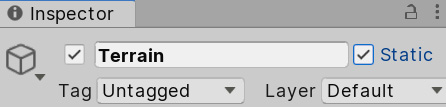
Figure 8.44 – Static checkbox
- Repeat this for every static object (this isn't necessary for lights; we will deal with those later).
Consider that you may not want every object, even if it's static, to be lightmapped, because the more objects you lightmap, the more texture size you will require. As an example, the terrain is too large and will consume most of the lightmapping's size. Usually, this is necessary, but in our case, the Spotlights are barely touching the terrain. Here, we have two options: leave the terrain as dynamic, or better, directly tell the Spotlights to not affect the terrain since one is only lit by ambient lighting and the Directional Light (which is not casting shadows). Remember that this is something we can do because of our type of scene; however, you may need to use other settings in other scenarios. You can exclude an object from both Realtime and Static lighting calculations by doing the following:
- Select the object to exclude.
- In the Inspector window, click the Layer dropdown and click on Add Layer:
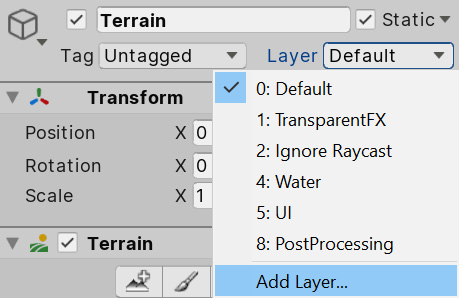
Figure 8.45 – Layer creation button
- Here, you can create a layer, which is a group of objects that's used to identify which objects are not going to be affected by lighting. In the Layers list, look for an empty space and type in any name for those kinds of objects. In my case, I will only exclude the terrain, so I have just named it Terrain:
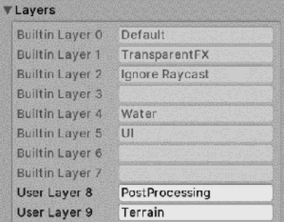
Figure 8.46 – Layers list
- Once again, select the terrain, go to the Layer dropdown, and select the layer you created in the previous step. This way, you can specify that this object belongs to that group of objects:
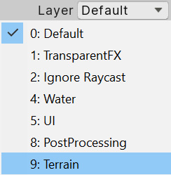
Figure 8.47 – Changing a GameObject's layer
- Select all the Spotlights lights, look for the Culling Mask in the Inspector window, click it, and uncheck the layer you created previously. This way, you can specify that those lights won't affect that group of objects:
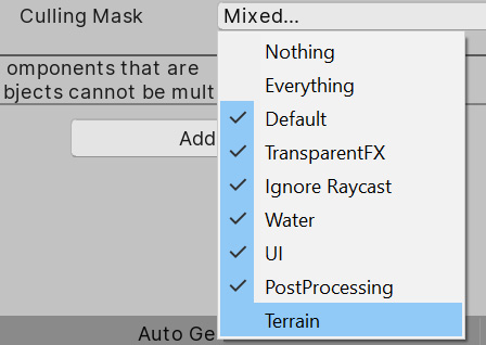
Figure 8.48 – Light Culling Mask
- Now, you can see how those selected lights are not illuminating or applying shadows to the terrain.
Now, it's time for the lights since the Static checkbox won't work for them. For them, we have the following three modes:
- Realtime: A light in Realtime mode will affect all objects, both static and dynamic, using Realtime lighting, meaning there's no precalculation. This is useful for lights that are not static, such as the player's flashlight, a lamp that is moving due to the wind, and so on.
- Baked: The opposite of Realtime, this kind of light will only affect static objects with lightmaps. This means that if the player (dynamic) moves under a baked light on the street (static), the street will look lit, but the player will still be dark and won't cast any shadows on the street. The idea is to use this on lights that won't affect any dynamic object, or on lights that are barely noticeable on them, so that we can increase performance by not calculating them.
- Mixed: This is the preferred mode if you are not sure which one to use. This kind of light will calculate lightmaps for static objects, but will also affect dynamic objects, combining its Realtime lighting with the baked one (like Realtime lights also do).
In our case, our Directional Light will only affect the terrain, and because we don't have shadows, applying lighting to it is relatively cheap in URP, so we can leave the Directional Light in Realtime so that it won't take up any lightmap texture area. Our spotlights are affecting the base, but actually, they are only applying lighting to it – we have no shadows because our base is empty. In this case, it is preferable to not calculate lightmapping whatsoever, but for learning purposes, I will add a few objects as obstacles to the base to cast some shadows and justify the use of lightmapping, as shown in the following figure:

Figure 8.49 – Adding objects to project light
Here, you can see how the original design of our level changes constantly during the development of the game, and that's something you can't avoid – bigger parts of the game will change in time. Now, we are ready to set up the Light Modes and execute the baking process, as follows:
- Select Directional Light.
- Set Render Mode in the Inspector window to Realtime (if it's not already in that mode).
- Select both Spotlights.
- Set their Render Mode to Mixed:
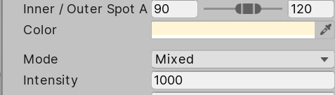
Figure 8.50 – Mixed lighting setting
- Open the Lighting Settings window (Window | Rendering | Lighting Settings).
- Click Generate Lighting, which is the same button we used previously to generate ambient lighting.
- Wait for the process to complete. You can do this by checking the progress bar at the bottom-right of the Unity Editor. Note that this process could take hours in large scenes, so be patient:

Figure 8.51 – Baking progress bar
- We want to change some of the settings of the baking process. In order to enable the controls for this, click the New Lighting Settings button. This will create an asset with lightmapping settings that can be applied to several scenes in case we want to share the same settings multiple times:

Figure 8.52 – Creating lighting settings
- Reduce the quality of lightmapping, just to make the process go faster. Just to iterate, the lighting can easily be reduced by using settings such as Lightmap Resolution, Direct, Indirect, and Environment Samples. In my case, I have those settings applied, as shown in the following figure. Note that even reducing those will take time; we have too many objects in the scene due to the modular level design:

Figure 8.53 – Scene lighting settings
- After the process has completed, you can check the bottom part of the Lighting Settings window, where you can see how many lightmaps need to be generated. We have a maximum lightmap resolution, so we probably need several of them to cover the entire scene. Also, it informs us of their size so that we can consider their impact in terms of RAM. Finally, you can check out the Baked Lightmaps section to see them:

Figure 8.54 – Generated lightmaps
- Now, based on the results, you can move objects, modify light intensities, or make whatever correction you would need in order to make the scene look the way you want and recalculate the lighting every time you need to. In my case, those settings gave me good enough results, which you can see in the following figure:

Figure 8.55 – Lightmap result
We still have plenty of small settings to touch on, but I will leave you to discover those through trial and error or by reading the Unity documentation about lightmapping at this link. Reading the Unity manual is a good source of knowledge and I recommend that you start using it – any good developer, no matter how experienced, should read the manual.
Applying static lighting to static objects
When marking objects as static in your scene, you've probably figured out that all the objects in the scene won't move, so you probably checked the static checkbox for every one. That's OK, but you should always put a dynamic object into the scene to really be sure that everything works OK – no games have totally static scenes. Try adding a capsule and moving it around to simulate our player, as shown in the following figure. If you pay attention to it, you will notice something odd – the shadows being generated by the lightmapping process are not being applied to our dynamic object:
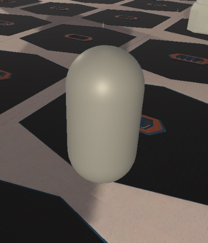
Figure 8.56 – Dynamic object under a lightmap's precalculated shadow
You may be thinking that Mixed Light Mode was supposed to affect both dynamic and static objects, and that is exactly what it's doing. The problem here is that everything related to static objects is precalculated into those lightmap textures, including the shadows they cast, and because our capsule is dynamic, it wasn't there when the precalculation process was executed. So, in this case, because the object that cast the shadow was static, its shadow won't affect any dynamic object.
Here, we have several solutions. The first would be to change the Static and Realtime mixing algorithm to make everything near the camera use Realtime lighting and prevent this problem (at least near the focus of attention of the player), which would have a big impact on performance. The alternative is to use Light Probes. When we baked information, we only did that on lightmaps, meaning that we have information on lighting just over surfaces, not in empty spaces. Because our player is traversing the empty spaces between those surfaces, we don't know exactly how the lighting would look in those spaces, such as the middle of a corridor. Light Probes are a set of points in those empty spaces where Unity also pre-calculates information, so when some dynamic object passes through it, it will sample information from it. In the following figure, you can see some Light Probes that have been applied to our scene. You will notice that the ones that are inside shadows are going to be dark, while the ones exposed to light will have a greater intensity. This effect will be applied to our dynamic objects:

Figure 8.57 – Spheres representing Light Probes
If you move your object through the scene now, it will react to the shadows, as shown in the following two images, where you can see a dynamic object being lit outside a baked shadow and being dark inside:
.jpg)
Figure 8.58 – Dynamic object receiving baked lighting from Light Probes
In order to create Light Probes, do the following:
- Create a group of Light Probes by going to GameObject | Light | Light Probe Group:
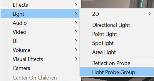
Figure 8.59 – Creating a Light Probe Group
- Fortunately, we have some guidelines on how to locate them. It is recommended to place them where the lighting changes, such as inside and outside shadow borders. However, that is pretty complicated. The simplest and recommended approach is to just drop a grid of Light Probes all over your playable area. To do that, you can simply copy and paste the Light Grid Group several times to cover the entire base:
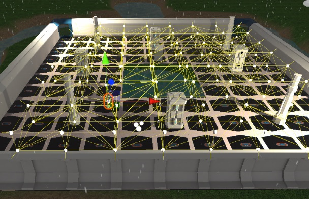
Figure 8.60 – Light Probe grid
- Another approach would be to select one group and click the Edit Light Probes button to enter Light Probe edit mode:
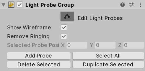
Figure 8.61 – Light Probe Group edit button
- Click the Select All button and then Duplicate Selected to duplicate all the previously existing probes.
- Using the translate gizmo, move them next to the previous ones, extending the grid in the process. Consider that the nearer the probes are, you will need more to cover the terrain, which will generate more data. However, Light Probes data is relatively cheap, so you can have lots of them.
- Repeat steps 4 to 5 until you've covered the entire area.
- Regenerate lighting with the Generate Lighting button in Lighting Settings.
With that, you have precalculated lighting on the Light Probes affecting our dynamic objects, combining both worlds to get cohesive lighting.
Summary
In this chapter, we discussed several lighting topics, such as how Unity calculates lights, shadows, how to deal with different light sources such as direct and indirect lighting, how to configure shadows, how to bake lighting to optimize performance, and how to combine dynamic and static lighting so that the lights aren't disconnected from the world they affect. This was a long chapter, but lighting deserves that. It is a complex subject that can improve the look and feel of your scene drastically, as well as reducing your performance dramatically. It requires a lot of practice and, here, we tried to summarize all the important knowledge you will need to start experimenting with it. Be patient with this topic; it is easy to get incorrect results, but you are probably just one checkbox away from solving it.
Now that we have improved all we can in the scene settings, in the next chapter, we will apply a final layer of graphic effects using the Unity Postprocessing Stack, which will apply full-screen image effects – ones that will give us that cinematic look and feel all games have nowadays.