
Chapter 12: Creating Animations with Animator, Cinemachine, and Timeline
At our current game status, we mostly have a static Scene, without considering the Shader and particle animations. In the next chapter, when we will add scripting to our game, everything will start to move according to the behavior we want. But sometimes, we need to move objects in a predetermined way, such as with cutscenes, or specific character animations, such as jumping, running, and so on. The idea of this chapter is to go over several Unity animation systems to create all the possible movements of objects we can get without scripting.
In this chapter, we will examine the following animation concepts:
- Using skeletal animations with Animator
- Creating dynamic cameras with Cinemachine
- Creating cutscenes with Timeline
By the end of this chapter, you will be able to create cutscenes to tell the history of your game or highlight specific areas of your level, as well as create dynamic cameras that are capable of giving an accurate look of your game, regardless of the situation.
Using skeletal animations with Animator
So far, we have used what are called static meshes, which are solid three-dimensional models that are not supposed to bend or animate in any way (aside from moving separately, like the doors of a car). We also have another kind of mesh, called skinned meshes, which are meshes that have the ability to be bent based on a skeleton, so they can emulate the muscle movements of the human body. We are going to explore how to integrate animated humanoid characters into our project to create the enemy and player movements.
In this section, we will examine the following skeletal mesh concepts:
- Understanding skinning
- Importing skinned meshes
- Integration using Animator Controllers
We are going to explore the concept of skinning and how it allows you to animate characters. Then, we are going to bring animated meshes into our project to finally apply animations to them. Let's start by discussing how to bring skeletal animations into our project.
Understanding skinning
In order to get an animated mesh, we need to have four pieces, starting with the mesh itself and the model that will be animated, which is created the same way as any other mesh. Then, we need the skeleton, which is a set of bones that will match the desired mesh topology, such as the arms, fingers, feet, and so on. In Figure 12.1, you can see an example of a set of bones aligned with our target mesh. You will notice that these kinds of meshes are usually modeled with the T pose, which will facilitate the animation process:
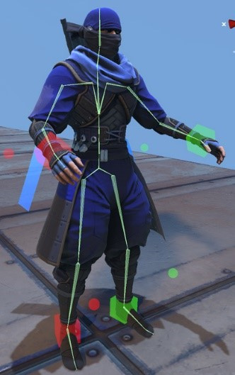
Figure 12.1 – A ninja mesh with a skeleton matching its default pose
Once the artist has created the model and its bones, the next step is to do the skinning, which is the act of associating every vertex of the model to one or more bones. In this way, when you move a bone, the associated vertexes will move with it. This is done in such a way because it is easier to animate a reduced amount of bones instead of every single vertex of the model. In the next screenshot, you will see the triangles of a mesh being painted according to the color of the bone that affects it as a way to visualize the influence of the bones. You will notice blending between colors, meaning that those vertexes are affected differently by different bones to allow the vertexes near an articulation to bend nicely. Also, the screenshot illustrates an example of a two-dimensional mesh used for two-dimensional games, but the concept is the same:

Figure 12.2 – Mesh skinning weights visually represented as colors
Finally, the last piece you need is the actual animation, which will simply consist of a blending of different poses of the meshes. The artist will create keyframes in an animation, determining which pose the model needs to have at different moments, and then the animation system will simply interpolate between them. Basically, the artist will animate the bones, and the skinning system will apply this animation to the whole mesh. You can have one or several animations, which you will later switch between according to the animation that you want to match the character's motion (such as idle, walking, falling, and so on).
In order to get the four parts, we need to get the proper assets containing them. The usual format in this scenario is Filmbox (FBX), which is the same that we have used so far to import 3D models. This format can contain every piece we need—the model, the skeleton with the skinning, and the animations—but usually, we will split the parts into several files to reutilize the pieces.
Imagine a city simulator game where we have several citizen meshes with different aspects and all of them must be animated. If we have a single FBX per citizen containing the mesh, the skinning, and the animation, it will cause each model to have its own animation, or at least a clone of the same one, repeating them. When we need to change that animation, we will need to update all the mesh citizens, which is a time-consuming process. Instead of this, we can have one FBX per citizen, containing the mesh and the bones with the proper skinning based on that mesh, as well as a separate FBX for each animation, containing the same bones that all the citizens have with the proper animation, but without the mesh. This will allow us to mix and match the citizen FBX with the animation's FBX files. You may be wondering why both the model FBX and the animation FBX must have the mesh. This is because they need to match in order to make both files compatible. In the next screenshot, you can see how the files should look:

Figure 12.3 – The animation and model FBX files of the package we will use in our project
Also, it is worth mentioning a concept called retargeting. As we said before, in order to mix a model and an animation file, we need them to have the same bone structure, which means the same amount of bones, hierarchy, and names. Sometimes, this is not possible, especially when we mix custom models created by our artist with external animation files that you can record from an actor using motion capture techniques or just by buying a Mocap library. In such cases, it is highly likely that you will encounter different bone structures between the one in the Mocap library and your character model, so here is where retargeting kicks in. This technique allows Unity to create a generic mapping between two different humanoid-only bone structures to make them compatible. In a moment, we will see how to enable this feature.
Now that we understand the basics behind skinned meshes, let's see how we can get the model's assets with bones and animations.
Importing skeletal animations
Let's start with how to import some animated models from the Asset Store, under the 3D | Characters | Humanoids section. You can also use external sites, such as Mixamo, to download them. But for now, I will stick to the Asset Store as you will have less trouble making the assets work. In my case, I have downloaded a package, as you can see in the following screenshot, that contains both models and animations.
Note that sometimes you will need to download them separately because some assets will be model- or animation-only. Also, consider that the packages used in this book might not be available at the time you're reading; in that case, you can either look for another package with similar assets (characters and animations, in this case) or download the project files from the GitHub repository of the book and copy the required files from there:
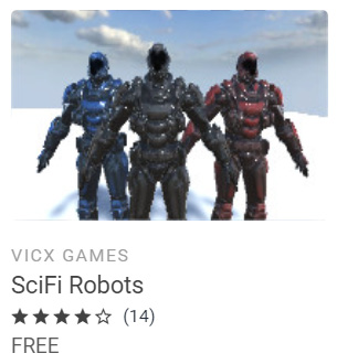
Figure 12.4 – Soldier models for our game
In my package content, I can find the animation's FBX files in the Animations folder and the single model FBX file in Model. Remember that sometimes you won't have them separated like this, and the animations may be located in the same FBX as the model, if any animations are present at all. Now that we have the required files, let's discuss how to properly configure them.
Let's start selecting the Model file and checking the Rig tab. Within this tab, you will find a setting called Animation Type, as in the following screenshot:

Figure 12.5 – The Rig properties
This property contains the following options:
- None: Mode for non-animated models; every static mesh in your game will use this mode.
- Legacy: The mode to be used in old Unity Projects and models; do not use this in new projects.
- Generic: A new animation system that can be used in all kinds of models but is commonly used in non-humanoid models, such as horses, octopuses, and so on. If you use this mode, both the model and animation FBX files must have the exact same bone names and structure, thereby reducing the possibility of combining animation from external sources.
- Humanoid: New animation systems designed to be used in humanoid models. It enables features such as retargeting and Inverse Kinematics (IK). This allows you to combine models with different bones than the animation because Unity will create a mapping between those structures and a generic one, called the avatar. Take into account that sometimes the automatic mapping can fail, and you will need to correct it manually; so, if your generic model has everything you need, I would recommend you to stick to Generic if that's the default configuration of the FBX.
In my case, the FBX files in my package have the modes set to Humanoid, so that's good, but remember, only switch to other modes if it is absolutely necessary (for example, if you need to combine different models and animations). Now that we have discussed the Rig settings, let's talk about the Animation settings.
In order to do this, select any animation FBX file and look for the Animation section of the Inspector window. You will find several settings, such as the Import Animation checkbox, which must be marked if the file has an animation (not the model files), and the Clips list, where you will find all the animations in the file. In the following screenshot, you can see the Clips list for one of our animation files:
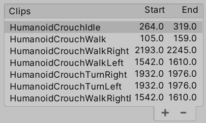
Figure 12.6 – A Clips list in the Animation settings
An FBX file with animations usually contains a single large animation track, which can contain one or several animations. Either way, by default, Unity will create a single animation based on that track, but if that track contains several animations, you will need to split them manually. In our case, our FBX contains several animations already split by the package creator, but in order to learn how to do a manual split, do the following:
- From the Clips list, select any animation that you want to recreate; in my case, I will choose HumanoidCrouchIdle.
- Take a look at the Start and End values below the animation timeline and remember them; we will use them to recreate this clip:
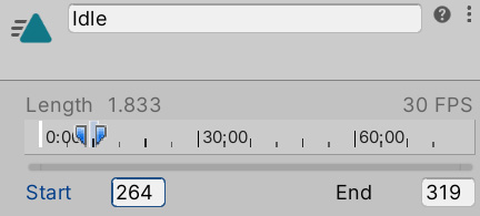
Figure 12.7 – The Clip settings
- Click on the minus button on the bottom-right part of the Clips list to delete the selected clip.
- Use the plus button to create a new clip and select it.
- Rename it to something similar to the original using the Take 001 input field. In my case, I will name it Idle.
- Set the End and Start properties with the values we needed to remember in Step 2. In my case, I have 319 for End and 264 for Start. This information usually comes from the artist, but you can just try the number that works best or simply drag the blue markers in the timeline on top of these properties.
- You can preview the clip by clicking on the bar titled for your animation (HumanoidIdle, in my case) at the very bottom of the Inspector window and click on the Play button. You will see the default Unity model, but you can see your own by dragging the model file to the preview window because it is important to check whether our models are properly configured. If the animation does not play, you will need to check whether the Animation Type setting matches the animation file:

Figure 12.8 – Animation preview
Now, open the animation file, click on the arrow, and check the sub-assets. You will see that here, there is a file titled for your animation, alongside the other animations in the clip list, which contains the cut clips. In a moment, we will play them. In the following screenshot, you can see the animations in our .fbx file:

Figure 12.9 – Generated animation clips
Now that we covered the basic configuration, let's see how to integrate animations.
Integration using Animation Controllers
When adding animations to our characters, we need to think about the flow of the animations, which means thinking about which animations must be played, when each animation must be active, and how transitions between animations should happen. In previous Unity versions, you needed to code that manually, generating complicated scripts of C# code to handle complex scenarios; but now, we have Animation Controllers.
Animation Controllers are a state machine-based asset where we can diagram the transition logic between animations with a visual editor called Animator. The idea is that each animation is a state and our model will have several of them. Only one state can be active at a time, so we need to create transitions in order to change them, which will have conditions that must be met in order to trigger the transition process. Conditions are comparisons of data about the character to be animated, such as its velocity, whether it's shooting or crouched, and so on.
So, basically, an Animation Controller or state machine is a set of animations with transition rules that will dictate which animation should be active. Let's start creating a simple Animation Controller by doing the following:
- Click the + button under the Project view, click on Animator Controller, and call it Player. Remember to locate your asset within a folder for proper organization; I will call mine Animators.
- Double-click on the asset to open the Animator window. Don't confuse this window with the Animation window; the Animation window does something different.
- Drag the Idle animation clip of your character into the Animator window. This will create a box in the Controller representing the animation that will be connected to the entry point of the Controller, indicating that the animation will be the default one because it is the first one that we dragged. If you don't have an Idle animation, I encourage you to find one. We will need at least one Idle and one walking/running animation clip:
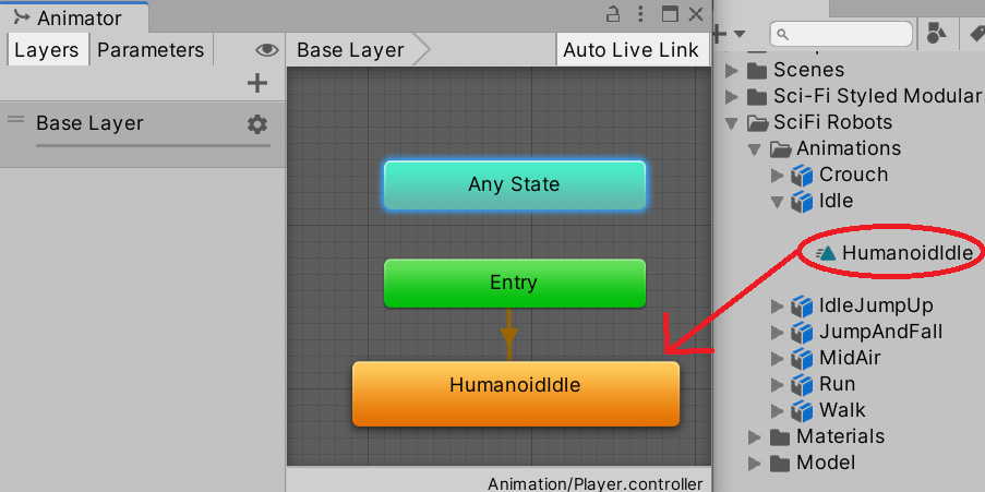
Figure 12.10 – Dragging an animation clip from an FBX asset into an Animator Controller
- Drag the running animation in the same way.
- Right-click on the Idle animation, select Create Transition, and left-click on the Run animation. This will create a transition between Idle and Run.
- Create another transition from Run to Idle in the same way:

Figure 12.11 – Transitions between two animations
Transitions must have conditions in order to prevent animations from swapping constantly, but in order to create conditions, we need data to make comparisons. We will add properties to our Controller, which will represent data used by the transitions. Later, in Part 3, we will set that data to match the current state of our object. But for now, let's create the data and test how the Controller reacts with different values. In order to create conditions based on properties, do the following:
- Click on the Parameters tab in the top-left part of the Animator window. If you don't see it, click on the crossed-eye button to display the tabs.
- Click on the + button and select Float to create a number that will represent the velocity of our character, naming it Velocity. If you missed the renaming part, just left-click on the variable and rename it:

Figure 12.12 – The Parameters tab with a float Velocity property
- Click on the Idle to Run transition (the white arrow) and look at the Conditions property in the Inspector window.
- Click on the + button at the bottom of the list, which will create a condition that will rule the transition. The default setting will take the first parameter of our animator (in this case, it is Velocity) and will set the default comparer, in this case, Greater, to a value of 0. This tells us that the transition will execute from Idle to Run if Idle is the current animation and the velocity of the Player is greater than 0. I recommend you to set a slightly higher value, such as 0.01, to prevent any float rounding errors (a common CPU issue). Also, remember that the actual value of Velocity needs to be set manually via scripting, which we will do in Part 3:
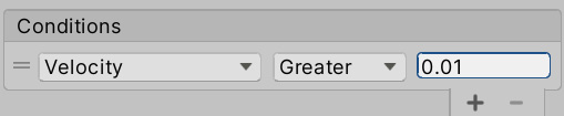
Figure 12.13 – Condition to check whether the velocity is greater than 0.01
- Do the same to the Run to Idle transition, but this time, change Greater to Less and again set the value to 0.01:

Figure 12.14 – Condition to check whether a value is less than 0.01
Now that we have our first Animator Controller set up, it's time to apply it to an object. In order to do that, we will need a series of components. First, when we have an animated character, rather than a regular Mesh Renderer, we use the Skinned Mesh Renderer. If you drag the model of the character to the scene and explore its children, you will see a component, as shown:
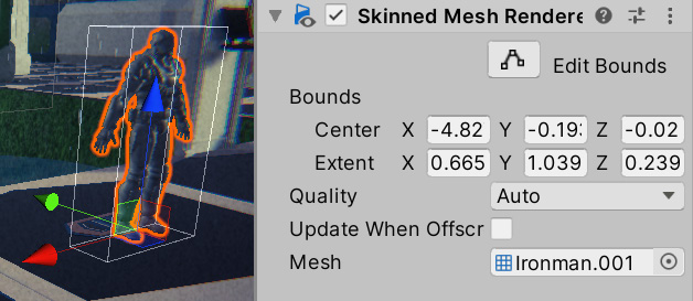
Figure 12.15 – A Skinned Mesh Renderer component
This component will be in charge of applying the bones' movements to the mesh. If you search the children of the model, you will find some bones; you can try rotating, moving, and scaling them to see the effect, as shown in the following screenshot. Consider the fact that your bone hierarchy might be different from mine if you downloaded another package from the Asset Store:

Figure 12.16 – Rotating the neckbone
The other component that we need is Animator, which is automatically added to skinned meshes at its root GameObject. This component will be in charge of applying the state machine that we created in the Animator Controller if the animation FBX files are properly configured as we mentioned earlier. In order to apply the Animator Controller, do the following:
- Drag the model of the character to the Scene if it's not already there.
- Select it and locate the Animator component in the root GameObject.
- Click on the circle to the right of the Controller property and select the Player controller we created earlier. You can also just drag it from the Project window.
- Make sure that the Avatar property is set to the avatar inside the FBX model; this will tell the animator that we will use that skeleton. You can identify the avatar asset by its icon of a person, as in the following screenshot. Usually, this property is correctly set automatically when you drag the FBX model to the Scene:
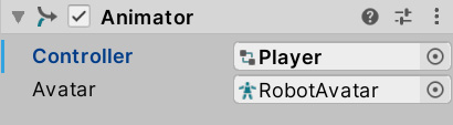
Figure 12.17 – Animator using the Player controller and the robot avatar
- Set the Camera GameObject so that it's looking at the player and play the game, and you will see the character executing its Idle animation.
- Without stopping the game, open the Animator Controller asset again by double-clicking it and selecting the character in the Hierarchy pane. By doing this, you should see the current state of the animation being played by that character, using a bar to represent the current part of the animation:
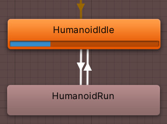
Figure 12.18 – The Animator Controller in Play mode while an object is selected, showing the current animation and its progress
- Using the Animator window, change the value of Velocity to 1.0 and see how the transition will execute:
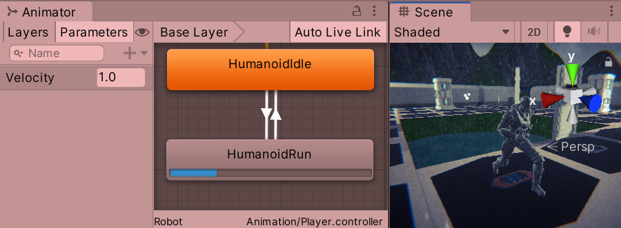
Figure 12.19 – Setting the velocity of the Controller to trigger a transition
Depending on how the Run animation was set, your character might start to move. This is caused by the root motion, a feature that will move the character based on the animation movement. Sometimes, this is useful, but due to the fact that we will fully move our character using scripting, we want that feature to be turned off. You can do that by unchecking the Apply Root Motion checkbox in the Animator component of the Character object:

Figure 12.20 – Disabled root motion
- You will also notice a delay between changing the Velocity value and the start of the animation transition. That's because, by default, Unity will wait for the original animation to end before executing a transition, but in this scenario, we don't want that. We need the transition to start immediately. In order to do this, select each transition of the Controller and in the Inspector window, uncheck the Has Exit Time checkbox:
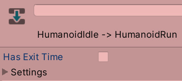
Figure 12.21 – Disabling the Has Exit Time checkbox to execute the transition immediately
You can start dragging other animations into the Controller and create complex animation logic, such as adding jumping, falling, or crouched animations. I invite you to try other parameter types, such as a Boolean, that use checkboxes instead of numbers. Also, as you develop your game further, your Controller will grow in its number of animations. To manage that, there are other features worth researching, such as Blend Trees and sub-state machines, but that's beyond the scope of this book.
Now that we understand the basics of character animations in Unity, let's discuss how to create dynamic camera animations to follow our player.
Creating dynamic cameras with Cinemachine
Cameras are a very important subject in video games. They allow the player to see their surroundings to make decisions based on what they see. The game designer usually defines how it behaves to get the exact gameplay experience they want, and that's no easy task. A lot of behaviors must be layered to get the exact feeling. Also, during cutscenes, it is important to control the path that the camera will be traversing and where the camera is looking to focus the action during those constantly moving scenes.
In this chapter, we will use the Cinemachine package to create both of the dynamic cameras that will follow the player's movements, which we will code in Part 3, and also, the cameras to be used during cutscenes.
In this section, we will examine the following Cinemachine concepts:
- Creating camera behaviors
- Creating dolly tracks
Let's start by discussing how to create a Cinemachine controlled camera and configure behaviors in it.
Creating camera behaviors
Cinemachine is a collection of different behaviors that can be used in the camera, which when properly combined can generate all kinds of common camera types in video games, including following the player from behind, first-person cameras, top-down cameras, and so on. In order to use these behaviors, we need to understand the concept of brain and virtual cameras.
In Cinemachine, we will only keep one main camera, as we have done so far, and that camera will be controlled by virtual cameras, separated GameObjects that have the previously mentioned behaviors. We can have several virtual cameras and swap between them at will, but the active virtual camera will be the only one that will control our main camera. This is useful for switching cameras at different points of the game, such as switching between our player's first-person camera. In order to control the main camera with the virtual cameras, it must have a Brain component.
To start using Cinemachine, first, we need to install it from the Package Manager, as we did previously with other packages. If you don't remember how to do this, just do the following:
- Go to Window | Package Manager.
- Ensure that the Packages option in the top-left part of the window is set to Unity Registry:

Figure 12.22 – The Packages filter mode
- Wait a moment for the left panel to populate all packages from the servers (internet is required).
- Look for the Cinemachine package from the list and select it. At the moment of writing this book, we are using Cinemachine 2.6.0.
- Click the Install button in the bottom-right corner of the screen.
Let's start creating a virtual camera to follow the character we animated previously, which will be our player hero. Do the following:
- Click Cinemachine | Create Virtual Camera. This will create a new object called CM vcam1:
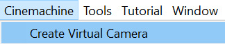
Figure 12.23 – Virtual camera creation
- If you select the main camera from the Hierarchy pane, you will also notice that a CinemachineBrain component has been automatically added to it, making our main camera follow the virtual camera. Try to move the created virtual camera, and you will see how the main camera follows it:

Figure 12.24 – The CinemachineBrain component
- Select the virtual camera and drag the character to the Follow and Look At properties of the Cinemachine virtual camera component. This will make the movement and looking behaviors use that object to do their jobs:
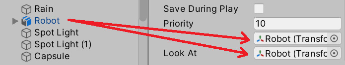
Figure 12.25 – Setting the target of our camera
- You can see how the Body property of the virtual camera is set to Transposer, which will move the camera relative to the target set at the Follow property; in our case the character. You can change the Follow Offset property and set it to the desired distance you want the camera to have from the target. In my case, I used the (0, 3, and -3) values:
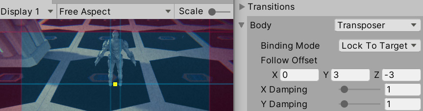
Figure 12.26 – The camera following the character from behind
- Figure 12.26 shows the Game view; you can see a small, yellow rectangle indicating the target position to look at the character, and it's currently pointing at the pivot of the character—its feet. We can apply an offset in the Tracked Object Offset property of the Aim section of the virtual camera. In my case, a value of 0, 1.5, and 0 worked well to make the camera look at the chest instead:
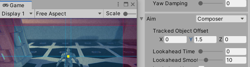
Figure 12.27 – Changing the Aim offset
As you can see, using Cinemachine is pretty simple, and in our case, the default settings were mostly enough for the kind of behavior we needed. However, if you explore the other Body and Aim modes, you will find that you can create any type of camera for any type of game. We won't cover the other modes in this book, but I strongly recommend you look at the documentation for Cinemachine to check what the other modes do. To open the documentation, do the following:
- Open the Package Manager by going to Window | Package Manger.
- Find Cinemachine in the left-hand side list. Wait a moment if it doesn't show up. Remember that you need an internet connection for it to work.
- Once Cinemachine is selected, look for the View documentation link in blue. Click on it:

Figure 12.28 – The Cinemachine documentation link
- You can explore the documentation using the navigation menu on the left:
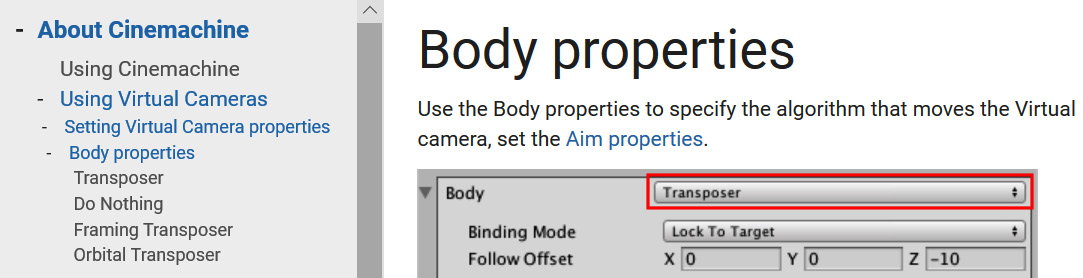
Figure 12.29 – The Cinemachine documentation
As you did with Cinemachine, you can find other packages' documentation in the same way. Now that we have achieved the basic camera behavior that we need, let's explore how we can use Cinemachine to create a camera for our intro cutscene.
Creating dolly tracks
When the player starts the level, we want a little cutscene with a pan over our scene and the base before entering the battle. This will require the camera to follow a fixed path, and that's exactly what Cinemachine's dolly camera does. It creates a path where we can attach a virtual camera so that it will follow it. We can set Cinemachine to move automatically through the track or follow a target to the closest point to the track; in our case, we will use the first option.
In order to create a dolly camera, do the following:
- Let's start creating the track with a cart, which is a little object that will move along the track, which will be the target to follow the camera. To do this, click on Cinemachine | Create Dolly Track with Cart:
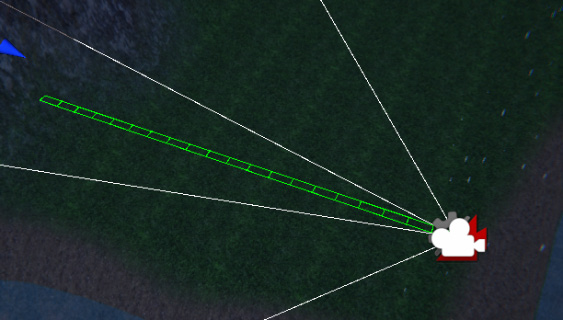
Figure 12.30 – A dolly camera with a default straight path
- If you select the DollyTrack1 object, you can see two circles with the numbers 0 and 1. These are the control points of the track. Select one of them and move it as you move other objects using the arrows of the translation gizmo.
- You can create more control points by clicking the + button at the bottom of the Waypoints list of the CinemachineSmoothPath component of the DollyTrack1 object:

Figure 12.31 – Adding a path control point
- Create as many waypoints as you need to create a path that will traverse the areas you want the camera to oversee in the intro cutscene. Remember, you can move the waypoints by clicking on them and using the translation gizmo:
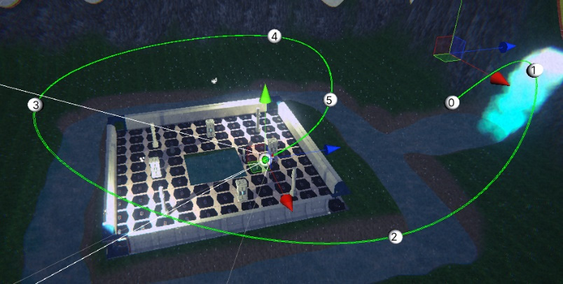
Figure 12.32 – A dolly track for our scene. It ends right behind the character
- Create a new virtual camera. If you go to the Game view after creating it, you will notice that the character camera will be active. In order to test how the new camera looks, select it and click on the Solo button in the Inspector window:
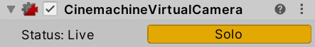
Figure 12.33 – The Solo button to temporarily enable this virtual camera while editing
- Set the Follow target this time to the DollyCart1 object that we previously created with the track.
- Set Follow Offset to 0, 0, and 0 to keep the camera in the same position as the cart.
- Set Aim to Same As Follow Target to make the camera look in the same direction as the cart, which will follow the track curves:

Figure 12.34 – Configuration to make the virtual camera follow the dolly track
- Select the DollyCart1 object and change the Position value to see how the cart moves along the track. Do this while the game window is focused and CM vcam2 is in solo mode to see how the camera will look:

Figure 12.35 – The Dolly Cart component
With the dolly track properly set, we can create our cutscene using Timeline to sequence it.
Creating cutscenes with Timeline
We have our intro camera, but that's not enough to create a cutscene. A proper cutscene is a sequence of actions happening at the exact moment that they should happen, coordinating several objects to act as intended. We can have actions such as enabling and disabling objects, switching cameras, playing sounds, moving objects, and so on. To do this, Unity offers Timeline, which is a sequencer of actions to coordinate that kind of cutscenes. We will use Timeline to create an intro cutscene for our scene, showing the level before starting the game.
In this section, we will examine the following Timeline concepts:
- Creating animation clips
- Sequencing our intro cutscene
We are going to see how to create our own animation clips in Unity to animate our GameObjects and then place them inside a cutscene to coordinate their activation using the Timeline sequencer tool. Let's start creating a camera animation to use later in Timeline.
Creating animation clips
This is actually not a Timeline-specific feature, but rather a Unity feature that works great with Timeline. When we downloaded the character, it came with animation clips that were created using external software, but you can create custom animation clips using Unity's Animation window. Don't confuse it with the Animator window, which allows us to create animation transitions that react to the game situation. This is useful to create small object-specific animations that you will coordinate later in Timeline with other objects' animations.
These animations can control any value of an object's component properties, such as the positions, colors, and so on. In our case, we want to animate the dolly track's Position property to make it go from start to finish in a given time. In order to this, do the following:
- Select the DollyCart1 object.
- Open the Animation (not Animator) window by going to Window | Animation | Animation.
- Click on the Create button at the center of the Animation window. Remember to do this while the dolly cart (not track) is selected:
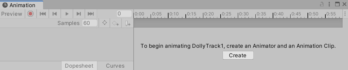
Figure 12.36 – Creating a custom animation clip
- After doing this, you will be prompted to save the animation clip somewhere. I recommend you create an Animations folder in the project (inside the Assets folder) and call it IntroDollyTrack.
If you pay attention, the dolly cart now has an Animator component with an Animator Controller created, which contains the animation we just created. As with any animation clip, you need to apply it to your object with an Animator Controller; custom animations are no exception. So, the Animation window created them for you.
Animating in this window consists of specifying the value of its properties at given moments. In our case, we want Position to have a value of 0 at the beginning of the animation at the second 0 at the timeline, and have a value of 240 at the end of the animation at second 5. I chose 240 because that's the last possible position in my cart, but that depends on the length of your dolly track. Just test which is the last possible position in yours. Also, I chose the second 5 because that's what I feel is the correct length for the animation, but feel free to change it as you wish. Now, whatever happens between the animation's 0 and 5 seconds is an interpolation of the 0 and 240 values, meaning that in 2.5 seconds, the value of Position will be 120. Animating always consists of interpolating different states of our object at different moments.
In order to do this, do the following:
- In the Animation window, click on the record button (the red circle in the top-left section). This will make Unity detect any changes in our object and save it to the animation. Remember to do this while you have selected the dolly cart.
- Set the Position setting of the dolly cart to 1 and then 0. Changing this to any value and then to 0 again will create a keyframe, which is a point in the animation that says that at 0 seconds, we want the Position value to be 0. We need to set it first to any other value if the value is already at 0. You will notice that the Position property has been added to the animation:

Figure 12.37 – The animation in Record mode after changing the Position value to 0
- Using the mouse scroll wheel, zoom out the timeline to the right of the Animation window until you see 5 seconds in the top bar:
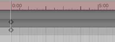
Figure 12.38 – The timeline of the Animation window showing 5 seconds
- Click on the 5 second label in the top bar of the timeline to position the playback header at that moment. This will locate the next change we do at that moment.
- Set the Position value of the dolly track to the highest value you can get; in my case, this is 240. Remember to have the Animation window in Record mode:

Figure 12.39 – Creating a keyframe with the 240 value at second 5 of the animation
- Hit the play button in the top-left section of the Animation window to see the animation playing. Remember to view it in the Game view and while CM vcam2 is in solo mode.
Now, if we hit play, the animation will start playing, but that's something we don't want. In this scenario, the idea is to give control of the cutscene to the cutscene system, Timeline, because this animation won't be the only thing that needs to be sequenced in our cutscene. One way to prevent the Animator component from automatically playing the animation we created is to create an empty animation state in the Controller and set it as the default state by doing the following:
- Search the Animator Controller that we created when we created the animation and open it. If you can't find it, just select the dolly cart and double-click on the Controller property of the Animator component on our Game Object to open the asset.
- Right-click on an empty state in the Controller and select Create State | Empty. This will create a new state in the state machine as if we created a new animation, but it is empty this time:
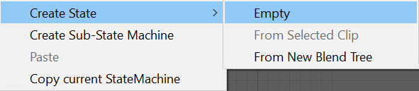
Figure 12.40 – Creating an empty state in the Animator Controller
- Right-click on New State and click on Set as Layer Default State. The state should become orange:

Figure 12.41 – Changing the default animation of the Controller to an empty state
- Now, if you hit play, no animation will play as the default state of our dolly cart is empty.
Now that we have created our camera animation, let's start creating a cutscene that switches from the intro cutscene camera to the player camera by using Timeline.
Sequencing our intro cutscene
Timeline is already installed in your project, but if you go to the Package Manager of Timeline, you may see an Update button to get the latest version if you need some of the new features. In our case, we will keep the default version included in our project (1.3.4, at the time of writing this book).
The first thing we will do is create a cutscene asset and an object in the scene responsible for playing it. To do this, follow these steps:
- Create an empty GameObject using the GameObject | Create Empty option.
- Select the empty object and call it Director.
- Go to Window | Sequencing | Timeline to open the Timeline editor.
- Click the Create button in the middle of the Timeline window while the Director object is selected to convert that object into the cutscene player (or director).
- After doing this, a window will pop up asking you to save a file. This file will be the cutscene or timeline; each cutscene will be saved in its own file. Save it in a Cutscenes folder in your project (the Assets folder).
- Now, you can see that the Director object has a Playable Director component with the Intro cutscene asset saved in the previous step set for the Playable property, meaning this cutscene will be played by the director:
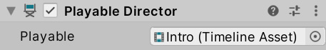
Figure 12.42 – Playable Director prepared to play the Intro Timeline asset
Now that we have the Timeline asset ready to work with, let's make it sequence actions. To start, we need to sequence two things—first, the cart position animation we did in the last step and then the camera swap between the dolly track camera (CM vcam2) and the player cameras (CM vcam1). As we said before, a cutscene is a sequence of actions executing at given moments, and in order to schedule actions, you will need tracks. In Timeline, we have different kinds of tracks, each one allowing you to execute certain actions on certain objects. We will start with the animation track.
The animation track will control which animation a specific object will play; we need one track per object to animate. In our case, we want the dolly track to play the Intro animation that we created, so let's do that doing the following:
- Create an Animation Track doing right click in the left part of the Timeline editor and clicking Animation Track:

Figure 12.43 – Creating Animation Track
- Select the Director object and check the Bindings list of the Playable Director component in the Inspector window.
- Drag the Cart object to specify that we want the animation track to control its animation:
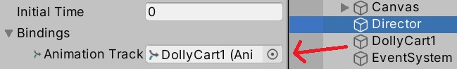
Figure 12.44 – Making the animation track control the dolly cart animation in this director
Important note:
Timeline is a generic asset that can be applied to any scene, but as the tracks control specifics objects, you need to manually bind them in every scene. In our case, we have an animation track that expects to control a single animator, so in every scene, if we want to apply this cutscene, we need to drag the specific animator to control in the Bindings list.
- Drag the Intro animation asset that we created to the animation track in the Timeline window. This will create a clip in the track showing when and for how long the animation will play. You can drag many animations that the cart can play into the track to sequence different animations at different moments; but right now, we want just that one:

Figure 12.45 – Making the animator track play the intro clip
- You can drag the animation to change the exact moment you want it to play. Drag it to the beginning of the track.
- Hit the Play button in the top-left part of the Timeline window to see it in action. You can also manually drag the white arrow in the Timeline window to view the cutscene at different moments:
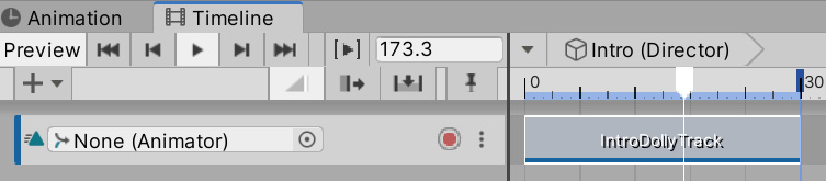
Figure 12.46 – Playing a timeline and dragging the playback header
Important note:
Remember that you don't need to use Timeline to play animations. In this case, we did it this way to control at exactly which moment we want the animation to play. You can control animators using scripting as well.
Now, we will make our Intro timeline asset tell the CinemachineBrain component (the main camera) which camera will be active during each part of the cutscene, switching to the player camera once the camera animation is over. We will create a second track—a Cinemachine track—which is specialized in making a specific CinemachineBrain component to switch between different virtual cameras. To do this, follow these steps:
- Right-click on the empty space below the animation track and click on Cinemachine Track. Note that you can install Timeline without Cinemachine, but this kind of track won't show up in that case:
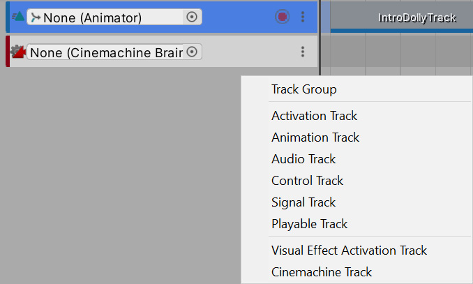
Figure 12.47 – Creating a new Cinemachine Track
- In the Playable Director component's Bindings list, drag the main camera to Cinemachine Track to make that track control which virtual camera will be the one that controls the main camera at different moments of the cutscene:

Figure 12.48 – Making the Cinemachine Track control our Scene's Main Camera
- The next step indicates which virtual camera will be active during specific moments of the timeline. To do so, our Cinemachine Track allows us to drag virtual cameras to it, which will create virtual camera clips. Drag both CM vcam2 and CM vcam1, in that order, to the Cinemachine Track:

Figure 12.49 – Dragging virtual cameras to the Cinemachine Track
- If you hit the play button or just drag the Timeline Playback header, you can see how the active virtual camera changes when the playback header reaches the second virtual camera clip. Remember to view this in the Game view.
- If you place the mouse near the ends of the clips, a resize cursor will show up. If you drag them, you can resize the clips to specify their duration. In our case, we will need to match the length of the CM vcam2 clip to the Cart animation clip and then put CM vcam1 at the end of it by dragging it so that the camera will be active when the dolly cart animation ends. In my case, they were already the same length, but just try to change it anyway to practice. Also, you can make the CM vcam1 clip be shorter; we just need that to play it for a few moments to execute the camera swap.
- You can also overlap the clips a little bit to make a smooth transition between the two cameras, instead of a hard switch, which will look odd:

Figure 12.50 – Resizing and overlapping clips to interpolate them
If you wait for the full cutscene to end, you will notice how at the very end, CM vcam2 becomes active again. You can configure how Timeline will deal with the end of the cutscene, as by default, it does nothing. This can cause different behavior according to the type of track; in our case, again giving the control to pick the virtual camera to the CinemachineBrain component, which will pick the virtual camera with the highest Priority value. We can change the Priority property of the virtual cameras to be sure that CM vcam1 (the player camera) is always the more important one, or set Wrap Mode of the Playable Director component to Hold, which will keep everything, as the last frame of the timeline specifies.
In our case, we will use the latter option to test the Timeline-specific features:
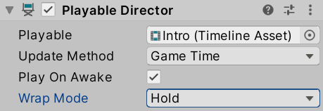
Figure 12.51 – Wrap Mode set to the Hold mode
Most of the different kinds of tracks work under the same logic; each one will control a specific aspect of a specific object using clips that will execute during a set time. I encourage you to test different tracks to see what they do, such as Activation, which enables and disables objects during the cutscene. Remember, you can check out the documentation of the Timeline package in the Package Manager.
Summary
In this chapter, we introduced the different animation systems that Unity provides for different requirements. We discussed importing character animations and controlling them with Animation Controllers. We also saw how to make cameras that can react to the game's current situation, such as the player's position, or that can used during cutscenes. Finally, we looked at Timeline and the animation system to create an intro cutscene for our game. These tools are useful for making the animators in our team work directly in Unity without the hassle of integrating external assets (except for character animations) and also preventing the programmer from creating repetitive scripts to create animations, wasting time in the process.
Now, you are able to import and create animation clips in Unity, as well as apply them to GameObjects to make them move according the clips. Also, you can place them in the Timeline sequencer to coordinate them and create cutscenes for your game. Finally, you can create dynamic cameras to use in-game or in cutscenes.
So far, we have discussed lots of Unity systems that allow us to develop different aspects of our game without coding, but sooner or later, scripting will be needed. Unity provides generic tools for generic situations, but our game's unique gameplay must usually be coded manually. In the next chapter, the first chapter of Part 3, we will start learning how to code in Unity using C#.