Drawing techniques for product design
The ability to explore large numbers of alternative concepts by externalizing thoughts on paper at the early stages of a design project is crucial. It will help to communicate your designs quickly and provide the client or fellow designer with a better impression of how a design would appear in reality.
Freehand drawing
When designers talk about drawing skills, what they most commonly mean is freehand perspective drawing ability. Fundamental to good drawing is the understanding and use of perspective technique.
There are three types of perspective drawings: one-point, two-point, and three-point (see p. 91). Each type can either be drawn in an accurate, measured way using plans and elevations of objects as guides, or drawn freehand. The understanding of perspective and an ability to draw well is vital if a designer is to gain a command of three-dimensional form and be able to accurately visualize products from his or her imagination. The quicker you are able to sketch and develop designs, the greater the number of projects you will be able to work through in a given time period and the more money you will be able to bring in to either your own business, or the design consultancy for which you work.

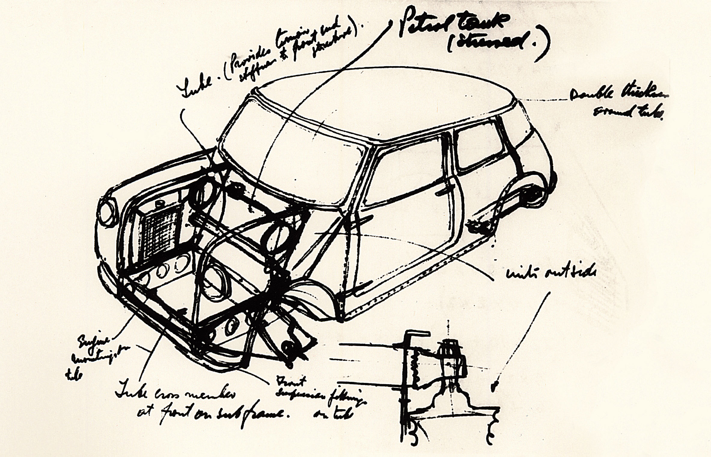
Prototype Mini project drawing, by Alec Issigonis, 1958. A renowned draftsman, this sketch shows the designer’s thinking behind the original groundbreaking Mini design, with its front-wheel drive, transverse engine, sump gearbox, small wheels, and phenomenal space efficiency that still inspires car designers and engineers today.
Concept sketching
Drawing enables designers to develop and evaluate their ideas on paper, storing concepts for later discussion, manipulation, and iterative development. The act of drawing works as a means of firming up an idea, enabling designers to wrestle with design possibilities, and attempt to give form and meaning to an idea. During the concept stage, designers have to visualize through a variety of techniques as yet non-existent product concepts.
Usually designers will start generating their ideas with a pen or pencil and paper. Most designers utilize these tools at these early stages of the design process because of the immediacy of the sketching process, the freedom provided, and the temporary nature (i.e. sketches can easily be erased, revised, and redrawn) of pencils and paper. A designer also annotates his or her sketches, with the notes acting as aide memoires while also helping identify key points so that the ideas can be communicated to members of the design team and all the stakeholders involved. Concept sketches allow one to see the designer’s mind at work. They fall into two broad categories: thematic sketches and schematic sketches.
Thematic sketches
These drawings are the initial exploratory visions of how a proposed design may look. They tend to be drawn in a willfully fluid, dynamic, and expressive manner, free from constraint. Thematic sketches should convey the product’s physical form, characteristics, and overall aesthetic. Such drawings often rely on a series of visual conventions that may need explanation to a client.
Schematic sketches
These drawings place less emphasis on the external styling or appearance of a design, and focus on defining and working within a “package”—the fixed dimensional parameters of a design, including vital data such as off-the-shelf components to be used and ergonomic parameters. Once a concept has been settled upon, the designer is able to move on to the production of presentation visuals to sell clients or investors the design. In the US he or she will then create a control drawing, detailing those aspects of the product that the designer has “control” over: it’s form, aesthetics, graphics, color, texture, finish, and so on. Today this usually takes the form of a computer-aided design (CAD) file, which is handed to an engineer or mechanical designer (or “CAD jockey”), who adds the details of interior parts to the file.
UK designers refer to a general arrangement (GA) drawing, which describes the design’s final form and the layout of its components, and acts as the key to the many working technical drawings required for manufacture and assembly. It provides information on overall dimensions and usually includes a parts list referring to other associated drawings, detailing the materials the parts are made from, surface finishes, and tolerances (dimensional accuracy required) of manufacturing. Once produced by hand using technical pens on drafting film, they are now produced using CAD.


Pito, designed by Frank O. Gehry for Alessi, 1992. Clockwise from top left: sketch, rendering, and final product. With just a few marks for the concept sketch, the essence of the final kettle design is already captured on paper during its development.
Rendering
Rendering is essentially the art of “coloring in” a sketch. Since the birth of industrial design in the 1920s, rendering has evolved into a discipline full of distinctive approaches, techniques, and conventions. The medium used in rendering is a more advanced form of the felt-tip pen, most commonly a Pantone Tria or Magic Marker. In addition to marker pens, chalk pastels in combination with talcum powder, colored pencils, and gouache paint are used to render drawings. The aim of a good rendering is to represent not only the color of a product, its material, and surface finish, but also how light is falling onto it.
Rendering is about giving an impression, rather than a true picture of reality. Provided enough information is supplied, the viewer’s mind can draw on visual experience to fill in the gaps. Rendering requires a bold approach for best results. Because it is so fast and immediate, it is best to avoid the precious approach so often taken when constructing a drawing. Sometimes young designers become overly concerned with slightly blurred edges or straying over the edge of a line, but this approach produces dull, static drawings instead of the fluid and expressive visuals that designers should aspire to and that always look more effective.
The real secret to rendering is realizing that you should be as economical as possible with your marks on paper but still manage to create an informative visual. These techniques can be applied to simple visuals or complex drawings that explain the assembly of a design, through what are known as exploded views. Being able to render convincingly is vital for the designer to be able to communicate design concepts quickly and in the presentation of concepts to clients.

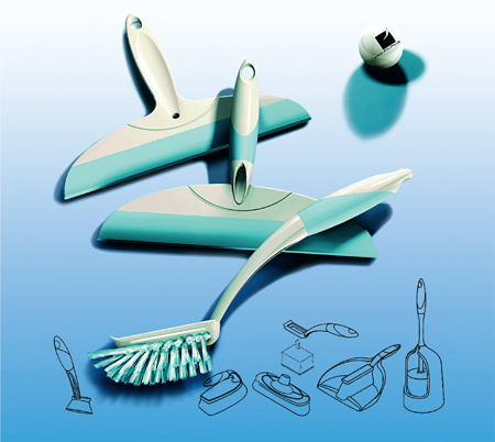
LINEA Collection, designed by pilipili for PDC Brush NV in Izegem, Belgium, 2003. Computer-rendered images of 3D models of household cleaning tools.

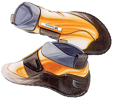
Concrete, by Jonas Hultqvist of Jonas Hultqvist Design, 2003. This is a project for Tretorn Sweden AB, a swedish shoe company with a history of innovation in rubber-made products, and these renderings show how they develop their new footwear concepts for internal and focus group evaluation.

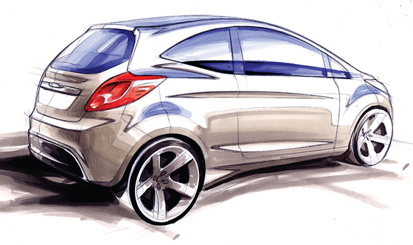
Ford Ka, 2008. This rendering of the secondgeneration model demonstrates the continued use and value of using traditional markers and pastels to quickly present design concepts.
Presentation visuals
During the concept generation phase, a product designer will often make hundreds of quick sketches while working on his or her designs for a new product. When a designer needs to present these ideas to the client and others, and communicate effectively the intentions of size, shape, scale, and materials, he or she will need to tidy up the rough sketches and present something more visually seductive. The product designer has to shift from a three-dimensional idea into a two-dimensional sketch, and then back again into a three-dimensional representation of that idea. It is here that the product designer must ensure that his or her two-dimensional flat drawing on a piece of paper conveys three-dimensional qualities and jumps out of the page at a client.
Software “Paint” packages that enable image manipulation have transformed the production of visuals in the design industry. Photoshop is the current market leader and the flagship product of Adobe Systems. It has been described as the industry standard for graphics professionals and played a large role in making the Apple Macintosh the designer’s computer of choice during the 1990s.
Although there are software packages specifically designed for two-dimensional sketching, which use styluses or graphic tablets for inputting data, most designers still draw on paper and then scan in their originals to be cleaned up and colored using Paint software. These packages enable the designer to use layers, and offer a variety of tools and filters that mimic traditional techniques, such as airbrushing, along with the ability to erase all steps. This is a method that designers in the past, with their laborious marker renderings, would undoubtedly have envied.
Drawing on computer
Drawing is a means to an end for designers, and enables them to produce physical products suitable for manufacture. Traditionally, when faced with a complex form, designers have relied on models made from styrofoam, clay, or cardboard to help them resolve their designs.
While plans, elevations, sections, and sketched isometric drawings may have been sufficient to move into three-dimensional modeling, these methods did not provide the required data to move into manufacture. Instead, this role relied on the highly developed craft skills of pattern-makers and panel beaters who interpreted the designers’ models and drawings, and as a consequence were effectively “co-designers” in bringing a design to production. These professions and the design skills they possessed have sadly faded away with the advent of three-dimensional CAD, which enables designers to sculpt, carve, and accurately dimension complex forms virtually.
Since its inception, CAD has undoubtedly enhanced the quality of presentation visuals, enabling designers to produce highly beguiling photorealistic images. The accurate modeling and animations possible have led to the establishment and expansion of specialist design disciplines and firms to sate the need for models, images, and technical data. CAD models have transformed the development process, allowing a designer to visualize his or her designs three-dimensionally without having to produce a full-size physical prototype or build a scale model, which often would take longer, and be more expensive, to produce. CAD is not, however, a replacement for physical modeling as there are still a number of important roles that physical models fulfill. Computer renderings do not capture the experiential or tactile qualities that models can convey, and can often appear to concretize a design in the development stage in the eyes of the design team or client. As the use of computer-generated graphics and special effects has entered mainstream media through film and television, photorealistic renderings have become the common parlance of design, but they lack the interpretive qualities of a hand-generated sketch or the subtlety of sculpting a form by hand.

This CAD exploded view of the Dyson BallTM technology, 2005, shows the components involved in this innovative design. It draws inspiration from the Ballbarrow that made Dyson’s name in 1974, where a sphere replaced a conventional wheel and enabled a user to steer the reinvented wheelbarrow around corners and obstacles with ease.

CAD wireframe image of Kelvin 40 concept Jet, designed by Marc Newson, commissioned and presented at Fondation Cartier, Paris, 2004. Newson famously doesn’t design on a computer, but spontaneously sketches to illustrate his ideas. Since the mid-1990s, the designs have been developed using 3D CAD software in his studio, headed by design manager Nicolas Register. However, Newson insists on seeing a physical prototype of the design before the final sign off.
In design development, CAD plays a key role in helping the designer to resolve issues such as complex arrangements of components or the form of aluminum or steel tools for plastic moldings or die-castings. CAD also helps to bring presentations to life by making designs seem more real at earlier stages of the design process.
There are two types of CAD modeler: surface modelers such as Studio Max, which were developed to satisfy the car design industry’s need for freeform design, and the solid modelers (also known as volumetric or geometric modelers) that rely on building forms from basic building blocks. Increasingly, software developers are merging the functionality of both systems to create packages suitable for designers and engineers.
Most solid modelers now enable parametric modeling, where parameters are used to define a CAD model’s dimensions or attributes. The advantage of parametric modeling is that a parameter may be modified later and the model will update to reflect the modification. This means designers no longer have to completely remodel a design when a change is made, enabling the software to become fully iterative.
Drafting, the technique of communicating technical details through a series of drawing conventions, has almost entirely been replaced by CAD. A product’s form, purpose, detailing, and specification can be developed collaboratively on screen. However, the conventions of traditional drafting remain the foundation for two-dimensional CAD drafting packages such as Autocad, which are universally used in design and manufacturing, and it is still essential that designers understand the underlying principles of traditional drawing conventions as these can help with sketches and choice of appropriate visuals. Meanwhile, CAD models are often required to be directly outputted to computer-aided manufacture (CAM) or rapid prototyping machines for purposes of prototyping or manufacture and therefore need to be highly accurate. Clients also want to be sure that the 3D CAD render they see in a presentation is what they will get once a product is actually produced.
