
Chapter 8. Implementing enterprise-quality message flows
In this chapter:
- Understanding error handling
- Using the Acegi framework
- Implementing an Apache LDAP server
- Using JAAS to secure ServiceMix
- Implementing transaction handling
Implementing message flows involves functionality such as routing, transformation, and connectivity. However, that’s not enough to implement enterprise integration solutions in real-life integration projects. You also need to be able to deal with, for example, error handling, security, and transactions. In this chapter, you’ll learn all the details.
Because message flows won’t run as expected all the time, we start this chapter with a discussion on error handling. It is essential (for the implementation of security and transactions as well) to be able to handle errors on all parts of a message flow. Because integration solutions typically deal with numerous messages, addressing errors is often difficult. A common solution is to send messages to error queues or “dead letter” queues, where ESB administrators can be alerted when an error occurs. You’ll see that implementing error-handling functionality is quite easy with Mule and ServiceMix.
Once error handling is in place, you can add security to a message flow. Error handling is a requirement when implementing security, because you encounter errors such as authentication and authorization failures. Security encompasses topics such as authentication, authorization, and message integrity. In the previous chapter, we discussed security in relation to web services, focusing on WS-Security. Because WS-Security deals with security on a message level, we focus in this chapter on security on an ESB container level. We look at the authentication and authorization of incoming messages in Mule and ServiceMix with security technologies like Lightweight Directory Access Protocol (LDAP) and Java Authentication and Authorization Service (JAAS).
In addition, we consider ways to implement transactional message flows in Mule and ServiceMix. A typical example of a transaction in a message flow is the consumption of a JMS message from a queue. The message will be consumed from the JMS queue only if the transactional processing of the message succeeds. If an error occurs, the transaction will be roll backed and the message will stay in the JMS queue. This is what was missing from the error-handling functionality that we just discussed. Although transaction handling is a complex topic, you’ll see that Mule and ServiceMix make it easy to implement transactional message flows.
By the end of this chapter, you’ll be able to implement complex message flows that take care of error handling, security, and transactions. Once you’ve experimented with the examples, you can consider yourself an integration professional!
8.1. Handling errors in your message flow
In the previous chapters you’ve seen a huge amount of functionality that can be used when implementing message flows in an open source ESB. But we’ve mainly talked about how to implement these message flows without taking into account possible errors and exceptions. When implementing message flows in real projects, error handling is an important part of the development work. In this section, we explore error handling in Mule and ServiceMix. First, let’s address the exception strategies of Mule, which provide the error-handling functionality we’re looking for.
8.1.1. Error handling with Mule
Mule features support to help you with handling errors during the runtime execution of a message flow. Errors and exceptions can occur at almost every step in the message flow, and therefore it’s important to have a fine-grained error-handling model at your disposal. For Mule, this means that you can define exception strategies to handle errors.
Two types of exception strategies are available: component and connector. The component exception strategy can be used to handle exceptions that have been thrown in Mule components. And because you’ll implement most Mule components yourself, this means that this exception strategy can be used to handle exceptions thrown by your own classes.
Connector exception strategies can be used to handle errors that are thrown by the connectors you use in your inbound and outbound endpoint definitions. For example, when an HTTP request fails in your outbound endpoint, the connector exception strategy can be used to handle this exception. Figure 8.1 shows a graphical overview of how you can use exception strategies in Mule.
Figure 8.1. Mule offers component and connector exception strategies.

Notice that we can define exception strategies on three levels: the model, the service, and the connector levels. The model and service levels can be used for component exception strategies, and the connector level can be used for the connector exception strategy. If no exception strategies are defined in a Mule configuration, the Mule container automatically applies the default exception strategies. These exception strategies log the error stack trace with Log4j and just pass the exception on. When an exception occurs in an HTTP connector, this means that the message flow will just stop processing.
For a decent error-handling mechanism, it’s therefore important to at least define an error queue or a dead letter queue to send error messages to. Listing 8.1 shows how easy the configuration of a dead letter queue is for handling component exceptions.
Listing 8.1. Configuring a dead letter queue
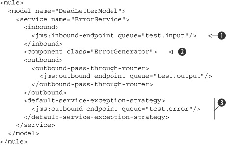
Listing 8.1 shows a simple service definition that listens for new messages on a JMS input queue
![]() . The incoming message is then passed on to the ErrorGenerator class
. The incoming message is then passed on to the ErrorGenerator class
![]() , which throws an exception during its message processing.
, which throws an exception during its message processing.
When an exception is thrown, the message isn’t passed on to the configured outbound router. If an exception strategy is configured,
as in this example
![]() , the exception is processed by this exception handler. In this case, the default exception strategy is used, which means
that the exception is passed on to the Default-ComponentExceptionStrategy class. This is the same class that handles the exception when no strategy is defined in the Mule configuration. The difference
is that we define an outbound endpoint for this exception strategy. The error message will now be sent to the defined JMS
queue.
, the exception is processed by this exception handler. In this case, the default exception strategy is used, which means
that the exception is passed on to the Default-ComponentExceptionStrategy class. This is the same class that handles the exception when no strategy is defined in the Mule configuration. The difference
is that we define an outbound endpoint for this exception strategy. The error message will now be sent to the defined JMS
queue.
The error message is a normal MuleMessage like every message that’s sent within the Mule container. The difference is that the payload or the content of the message is an ExceptionMessage. This ExceptionMessage class is a wrapper for the exception, the name of the component, the endpoint URI that caused the error, and a time-stamp. So when you want to build an error handler for an error queue like the test.error queue in listing 8.1, you’ll receive a message with this content.
Now that you’ve seen an example of a component exception strategy, let’s look at an example of a connector exception strategy. The exception handler for a connector is not that different from a component exception strategy, and you can also define an error queue with an outbound endpoint. But let’s see how a connector exception strategy is configured (listing 8.2).
Listing 8.2. Configuring a custom connector exception strategy in Mule

The exception strategy for a connector has to be defined as part of the connector configuration
![]() . This custom exception strategy class must extend the AbstractException-Listener or DefaultExceptionStrategy class. AbstractExceptionListener implements the ExceptionListener interface and can be used as a base class for custom exception strategies. DefaultExceptionStrategy implements the abstract methods of AbstractExceptionListener and can be used as a base class when you don’t want to implement a full-blown exception handler. For this example, it would
be sufficient to create a new class, which extends the DefaultExceptionStrategy and overrides the handleMessagingException or the defaultHandler method.
. This custom exception strategy class must extend the AbstractException-Listener or DefaultExceptionStrategy class. AbstractExceptionListener implements the ExceptionListener interface and can be used as a base class for custom exception strategies. DefaultExceptionStrategy implements the abstract methods of AbstractExceptionListener and can be used as a base class when you don’t want to implement a full-blown exception handler. For this example, it would
be sufficient to create a new class, which extends the DefaultExceptionStrategy and overrides the handleMessagingException or the defaultHandler method.
In addition to the outbound endpoint definition used as an error queue for the custom exception strategy defined in the routeException method of the AbstractExceptionListener class, you can inject properties via the Spring Framework as you can do with Spring beans
![]() .
.
In listing 8.2, the message flow is triggered when a JMS message arrives at the test.input queue. The message is then passed on to the outbound router, which invokes a web service over HTTP. This is, of course, an
oversimplified example, because in a real implementation you’d have to transform the JMS message to adhere to the message
format expected by the web service. To use the custom exception strategy
![]() , we have to link the outbound endpoint to the connector definition with the connector-ref attribute
, we have to link the outbound endpoint to the connector definition with the connector-ref attribute
![]() . When the HTTP call to the web service fails, the custom exception strategy is called with the exception message. The exception
will eventually be sent to an error queue, http.error, which can be used to trigger an error message flow or as a logging mechanism for error messages.
. When the HTTP call to the web service fails, the custom exception strategy is called with the exception message. The exception
will eventually be sent to an error queue, http.error, which can be used to trigger an error message flow or as a logging mechanism for error messages.
In section 8.2, we use exception strategies to catch authentication and authorization exceptions, so we’ll see some more examples later on. You now know how easy it is to configure exception strategies within Mule, so you should be able to implement error handling in your message flows as well. Next, let’s explore implementing error handling in ServiceMix.
8.1.2. Error handling in ServiceMix
You had a sneak preview of error handling in ServiceMix in chapter 5 (section 5.2), when we discussed message validation. Because we needed a way to catch validation errors in that example, we implemented a bean that caught fault messages and sent them on to an error queue. In this section, we look in greater detail into dealing with error handling in ServiceMix.
Let’s begin by discussing error handling as part of the JBI specification. As you know, the choice of a message exchange pattern is important when implementing a message flow in a JBI container such as ServiceMix. Let’s examine a typical example of error handling with an in-out message exchange (see figure 8.2).
Figure 8.2. An in-out message exchange with a fault response message. The normalized message router (NMR) ensures that the messages are sent between the binding components and service engines in the JBI container.

Figure 8.2 shows a typical request/response message flow that uses an HTTP binding component (BC). In this message flow, the incoming HTTP request is routed to a bean. In the JavaBean, an exception occurs and a fault message is returned to the NMR. Because the message exchange uses an in-out message exchange pattern, this fault message is sent back to the HTTP client via the HTTP BC.
So for a default request-response message flow, the error message is simply sent back to the requesting application. This is not always the desired behavior; in some cases the error message needs to be caught and another response message must be sent back to the client application. This involves more complex error-handling logic and custom code development.
When using an enterprise service bus, the communication style is often asynchronous (with only an incoming message) instead of synchronous. So let’s look at a typical example of an in-only message exchange with a JMS BC (see figure 8.3).
Figure 8.3. When a fault occurs in an in-only message exchange, the normalized message router doesn’t know how to route the fault message.

Notice that we use a JMS BC as a typical example of an in-only message exchange and an HTTP BC to explain an in-out message exchange. Both components can also be used with another message exchange pattern, but the common usage is shown in these figures. When an exception occurs in the bean component with an in-only message exchange, this still means that a fault message is sent to the NMR. However, the message flow will stop there because no routing path exists for the NMR to route the fault message to an endpoint. Therefore, the message flow is terminated and the exception is logged.
The one-way message flow example of figure 8.3 is rarely the desired behavior. Incoming messages should never get lost and should at least be logged for tracing and auditing purposes. Therefore, we need another component in the message flow that provides error-handling capabilities. There are several options to implement an error-handler component in ServiceMix. We already implemented a bean component error handler in chapter 5. That example, however, involves custom development, which isn’t necessary when you’re using a Camel component. Figure 8.4 provides an overview of the runtime message flow of a Camel error handler in a one-way message flow example.
Figure 8.4. A one-way message flow implementation that uses the Camel component as an error-handling mechanism for the invocation of the bean component
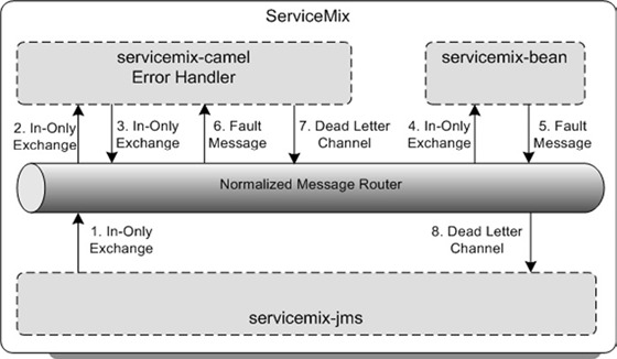
The Camel component provides a default error-handling mechanism that also includes redelivery policies to define such parameters as the maximum number of redeliveries. When a fault message is sent to the Camel component, as shown in figure 8.4, the error handler processes the fault message. The default error handler tries to redeliver the message to the bean component six times. When the message isn’t successfully consumed by the bean component after the sixth retry, the message is sent to the default dead letter channel, which is a log file. But you can also configure your own dead letter channel configuration to send the fault message to a JMS error queue (see listing 8.3).
Listing 8.3. Camel routing configuration with a custom dead letter channel

The Camel configuration can be implemented with a subclass of the RouteBuilder class. Because we use JBI services for the message flow implementation, we have to define a JBI service definition for the
Camel routing implementation
![]() . This JBI service name can now be used as a target JBI service for the JMS BC configuration.
. This JBI service name can now be used as a target JBI service for the JMS BC configuration.
In addition, we have to use the JBI service names. For example, the JBI service name for the error queue is configured as
a JMS provider in the JMS BC
![]() .
.
The message flow for the Camel component is defined in the configure method. Because the Camel component forwards the incoming message to the bean component, we can define a simple point-to-point
flow with the from and to methods. The custom error-handler definition can then be configured within this point-to-point flow
![]() . In listing 8.3, the error handler is configured as a dead letter channel which is actually a JMS queue. For this dead letter channel, we
can define redelivery policy parameters, such as the maximum number of redeliveries. The invocation of the bean component
will be retried twice, and then the message will be sent to the dead letter channel.
. In listing 8.3, the error handler is configured as a dead letter channel which is actually a JMS queue. For this dead letter channel, we
can define redelivery policy parameters, such as the maximum number of redeliveries. The invocation of the bean component
will be retried twice, and then the message will be sent to the dead letter channel.
The full example, including the JMS and Bean JBI component configurations, is available in the resources/chapter8/errorhandling directory. When you’ve started the ServiceMix container with the start target in the ch8-examples.xml Ant build file (resources/chapter8), you can deploy the error-handling example with the deploy-errorhandling target. With the Swing test client, the error-handling example can be triggered. The incoming JMS message is forwarded to the Camel component presented in listing 8.3, which will invoke the bean component and eventually send the message to the JMS error queue.
Error handling in ServiceMix is tightly coupled to the message exchange pattern used within a message flow. To be able to catch faults in a message flow, ServiceMix requires an additional JBI component to function as an error handler. It’s possible to implement an error handler in a bean component (as you saw in chapter 5), but Camel provides much more default error-handling functionality.
It’s time to move on to another important aspect of making your ESB enterprise ready: security. In the next section you’ll learn about different ways to implement security aspects such as authentication in Mule and ServiceMix. You’ll benefit from the knowledge you’ve gained about error handling to deal with authentication and authorization failures.
8.2. Securing the ESB environment
A hot topic for every IT project is security. The IT infrastructure is increasingly exposed to external systems such as the internet. But security issues don’t come only from the outside; some employees have a malicious intent while working with IT systems. So for both internal as well as external reasons, security is an important aspect. And because the ESB is a central system in an IT landscape, security is even more important when you’re implementing integration flows.
Security is a difficult topic to grasp; it deals with the identification of users of a system, but also with securing messages that are sent from one application to another to prevent somebody from changing the message content. From an ESB point of view, security can be categorized as authentication and authorization, secure transport, and integrity of the message. Authentication and authorization deals with the identification of a user (or application) and the rights this entity has. Secure transport ensures that messages can only be read by the intended recipient. Message integrity ensures that a message can’t be changed during the transport.
We now look at a number of examples showing how to implement authentication and authorization in Mule and ServiceMix. A number of handy configuration settings exist that let you easily configure an LDAP server and JAAS authentication and authorization rules in Mule and ServiceMix.
8.2.1. Authentication and authorization with Mule
The authentication and authorization model of Mule supports the Java Authentication and Authorization Service (JAAS) as well as Acegi. JAAS is the standard security framework of Java Standard Edition (SE), and Acegi is the security framework that’s part of the Spring Framework. Because the support for Acegi provides a richer set of functionality and because the JAAS framework is discussed in the ServiceMix section (8.2.2), we choose Acegi to implement the security examples for Mule.
Simple authentication with Mule and Acegi
Let’s start with a simple example. For the input of the simple authentication flow, we use command line console input, which consists of a username and password. When the console input is processed by Mule, a security filter is executed to authenticate the username and password against an in-memory list of users. The result of the authentication step is sent back to the console (see figure 8.5).
Figure 8.5. A simple example of how authentication can be implemented within Mule. A security filter will check the user credentials against an in-memory list of users.
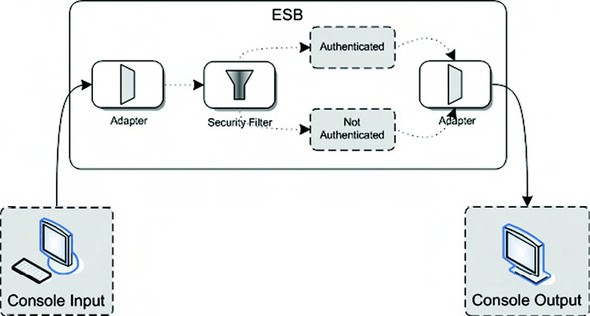
As you can see in figure 8.5, the authentication credentials are validated with a security filter. This security filter is provided with the Mule framework. Because the full Mule configuration for this example is quite large, it’s split into two parts. The first part (listing 8.4) contains the Acegi beans that are needed by the Mule container.
Listing 8.4. Part 1 of the simple authentication example showing the Acegi beans
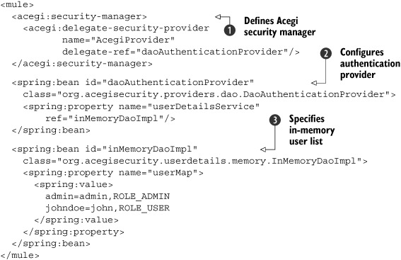
Security can be implemented in Mule by providing a security manager
![]() . The security filter (see listing 8.5 in a moment) uses the security manager configured in listing 8.4. You could configure the security manager with a number of security providers, but since we use Acegi, this is the provider
we use.
. The security filter (see listing 8.5 in a moment) uses the security manager configured in listing 8.4. You could configure the security manager with a number of security providers, but since we use Acegi, this is the provider
we use.
The integration between Mule and Acegi is achieved with the AcegiProvider-Adapter that’s configured with the delegate-security-provider element. This adapter converts the Mule authentication model into an Acegi security model and passes further authentication processing on to the delegate-ref. This delegate provides the actual authentication implementation that will be used. In this example, a database authentication provider is configured, as you can see with the daoAuthenticationProvider Spring bean, but Acegi also provides support for LDAP and JAAS, among others.
The database authentication provider of Acegi is also configured as a Spring bean
![]() . This provider is normally used to retrieve user information from a database. A JDBC implementation class, org.acegisecurity.userdetails.jdbc.JdbcDaoImpl, is available in Acegi that implements default queries that can be overridden. But to simplify the example, we use an in-memory
user list.
. This provider is normally used to retrieve user information from a database. A JDBC implementation class, org.acegisecurity.userdetails.jdbc.JdbcDaoImpl, is available in Acegi that implements default queries that can be overridden. But to simplify the example, we use an in-memory
user list.
For testing and example purposes, Acegi provides an in-memory DAO implementation
![]() . The userMap property can be used to inject a number of username/password/role combinations. In this example, we have two users, admin
and johndoe, in the administrator and user roles, respectively.
. The userMap property can be used to inject a number of username/password/role combinations. In this example, we have two users, admin
and johndoe, in the administrator and user roles, respectively.
With this simple configuration, we have created a Mule security manager that uses an Acegi in-memory user list to authenticate against. Now let’s look at the second part of the configuration (listing 8.5).
Listing 8.5. Part 2 of the simple authentication example showing the message flow

The second part contains quite a lot of interesting elements. Let’s look at the configuration in the order of the message
flow definition. When console input has been sent, the message is transformed in the outbound router with the SimpleAuthTransformer
![]() . The credentials that arrive via the console should be in the format username;password. The authentication transformer transforms that input into the message header credentials that Mule expects in its authentication
filter. The esb. chapter8.security.transformer.SimpleAuthenticationTransformer class uses the following two lines of code to set the credentials:
. The credentials that arrive via the console should be in the format username;password. The authentication transformer transforms that input into the message header credentials that Mule expects in its authentication
filter. The esb. chapter8.security.transformer.SimpleAuthenticationTransformer class uses the following two lines of code to set the credentials:
String muleCredentials = MuleCredentials.createHeader(
    username, password.toCharArray());
message.setProperty(MuleProperties.MULE_USER_PROPERTY,
    muleCredentials);
The MuleCredentials class is used to create the MULE_USER_PROPERTY header property. The message variable is a MuleMessage, which can be used to set the credentials as a property in the message header. We have to implement this credential creation ourselves because the VM connector doesn’t support authentication by default. With the HttpBasicAuthenticationFilter, Mule supports authentication without requiring you to customize the HTTP connector.
Now that the credentials have been set in the Mule message, we can authenticate the message with the security filter provided
by Mule
![]() . This security filter can only be used as an authentication filter for an inbound endpoint, so the message is forwarded to
the security.in virtual machine (VM) queue. The security filter is implemented by MuleEncryptionEndpointSecurityFilter; this class extracts the credentials from the Mule message and performs a check against the configured security manager. For
this example, this means that the username/password combination is checked against the in-memory user list (see listing 8.4).
. This security filter can only be used as an authentication filter for an inbound endpoint, so the message is forwarded to
the security.in virtual machine (VM) queue. The security filter is implemented by MuleEncryptionEndpointSecurityFilter; this class extracts the credentials from the Mule message and performs a check against the configured security manager. For
this example, this means that the username/password combination is checked against the in-memory user list (see listing 8.4).
We also have to define a strategy-ref attribute for the security filter that points to a Spring bean named keyEncryption. The keyEncryption bean defines an encryption strategy that will be used by the security filter to encrypt the credentials. However, the security filter only applies this encryption when it’s configured on an outbound endpoint. Therefore, the encryption strategy isn’t used in this example, but it must be set to let the security filter start up without errors.
When the authentication fails, the security filter throws an exception. With the default exception-handling strategy, this
means that the exception is logged and that the message flow stops immediately. However, we want to return a message to the
console indicating that authentication has failed. Therefore, we have to configure an endpoint on the exception handler for
the VM connector
![]() . This security.error VM queue is used by the default exception handler to forward the exception message without stopping the whole message flow.
By linking the inbound endpoint of the Mule service SimpleAuthService with this VM connector, we can retrieve the exception message from the error queue.
. This security.error VM queue is used by the default exception handler to forward the exception message without stopping the whole message flow.
By linking the inbound endpoint of the Mule service SimpleAuthService with this VM connector, we can retrieve the exception message from the error queue.
When the authentication succeeds, the message is passed on to the Authentication-Service. This class returns a simple message of “Has the user been authenticated? Authentication result.” The authentication result
is injected with the authenticated property
![]() . The same kind of configuration in another service definition has been implemented for the authentication failure flow, but
we leave this out to reduce the number of code lines in the listing. (The authenticated property is set to false for the authentication failure service.)
. The same kind of configuration in another service definition has been implemented for the authentication failure flow, but
we leave this out to reduce the number of code lines in the listing. (The authenticated property is set to false for the authentication failure service.)
You should now be able to test this example by executing the simpleAuth target in the ch8-examples.xml Ant script, which you can find in the resources/chapter8 directory. Then run the simpleauth.bat or simpleauth.sh script, available in the resources/chapter8/simpleauth directory, in a command console. When Mule starts, enter the credentials in the console. When you type admin;admin, the console should respond with “Has the user been authenticated? true.” And when you enter a nonexistent user, you should get a detailed exception stack trace and the message “Has the user been authenticated? false.”
In real life we don’t want to use an in-memory database to authenticate against. In the next section, we discuss the use of an LDAP server with Mule.
LDAP authentication with Mule and Acegi
Authentication and authorization information is often stored in a Lightweight Directory Access Protocol (LDAP) server. LDAP is a standardized protocol for the exchange of data across a network in a hierarchical way. The directory-based structure of LDAP is handy for categorizing user data, such as user roles and organizational information. Products like Microsoft Active Directory and Tivoli Directory Server are commonly used LDAP servers. Very good open source LDAP servers are also available, such as OpenLDAP and Apache Directory Server.
In this section we use Apache Directory Server, because it’s multiplatform and also provides a nice Eclipse-based administration tool. But does this mean that we have to implement a totally different Mule configuration than the example in the previous section? No, because we again use Acegi to provide a bridge between the Mule authentication functionality and the Apache Directory Server (see figure 8.6).
Figure 8.6. LDAP authentication implemented in Mule. Via HTTP, a request message with security context is consumed by the adapter, and the HTTP security filter validates the credentials against an LDAP server.
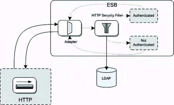
As shown in figure 8.6, the example will be implemented using an HTTP message channel. An HTTP adapter will accept HTTP requests that are expected to have credentials set in the HTTP header. Mule’s HTTP security filter will then check whether the credentials in the HTTP header are available in the LDAP server. Eventually a response is given back to the HTTP client with a message indicating whether the authentication has succeeded.
Let’s start with the installation of the Apache Directory Server. Go to the http://directory.apache.org website and download the latest ApacheDS (we use 1.5.2) and Apache Directory Studio (1.1.0) products. The installation procedure is simple and thus requires no additional explanation. The Windows version of Apache Directory Server contains an apacheds.exe file that will install the LDAP server as a Windows service. For the Linux distribution, you can start the LDAP server with the following command:
/etc/init.d/apacheds start
Now that we’ve started the LDAP server, we can look at its initial contents with the Apache Directory Studio. This is a simple but efficient Eclipse tool that you can use to create a new connection to your local LDAP server. Use the configuration shown in table 8.1 to configure the connection.
Table 8.1. Connection configuration to the Apache Directory Server
|
Connection parameter |
Parameter value |
|---|---|
| Connection name | local (or use your own name) |
| Hostname | localhost |
| Port | 10389 (or the port you configured during installation) |
| Encryption method | No encryption |
| Authentication method | Simple authentication |
| Bind DN or user | uid=admin,ou=system |
| Bind password | secret |
| Save password | yes |
Once you’ve made the connection, you should be able to access the LDAP server. The contents of the LDAP server will be similar to figure 8.7.
Figure 8.7. The initial contents of the Apache Directory Server shown in the Apache Directory Studio tool
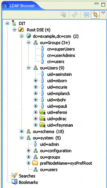
The number of groups in your LDAP server will be different than shown in figure 8.7 because we added an extra group for the example. (We discuss this with the listings in this section.) For now, it’s enough to see that we have a number of default users and groups available in the LDAP server.
Next let’s look at configuring Mule to use this LDAP server to authenticate the incoming HTTP request. We again divide the configuration into two parts; the first part (listing 8.6) contains the LDAP integration.
Listing 8.6. Part 1 of the LDAP authentication example containing the LDAP integration

To use an LDAP server as the authentication mechanism in Mule, we need to start by configuring a security manager (just as we did in the in-memory authentication example). The main difference is that here we use another authentication provider in the delegate-ref attribute.
The first part that we have to configure is the connection to the LDAP server
![]() . The Acegi framework provides a DefaultInitialDirContextFactory class that we can use to create this connection. This Acegi LDAP connection factory class needs a URI where it can find the
LDAP server as a constructor argument. The default port for the Apache Directory Server is 10389, and we can also configure
the default domain dc=example,dc=com in this URI. Then, we also need to provide a user with the managerDn property, so that the Acegi factory class can also authenticate the connection to the LDAP server.
. The Acegi framework provides a DefaultInitialDirContextFactory class that we can use to create this connection. This Acegi LDAP connection factory class needs a URI where it can find the
LDAP server as a constructor argument. The default port for the Apache Directory Server is 10389, and we can also configure
the default domain dc=example,dc=com in this URI. Then, we also need to provide a user with the managerDn property, so that the Acegi factory class can also authenticate the connection to the LDAP server.
With the LDAP connection information specified, we can configure the authentication provider
![]() that’s linked to the Mule security manager. The Acegi LdapAuthenticationProvider class needs two constructor arguments: an authentication query bean (Bind-Authenticator) and a role query bean (DefaultLdapAuthoritiesPopulator).
that’s linked to the Mule security manager. The Acegi LdapAuthenticationProvider class needs two constructor arguments: an authentication query bean (Bind-Authenticator) and a role query bean (DefaultLdapAuthoritiesPopulator).
The authentication query bean needs a connection to the LDAP server and a query to authenticate the user credentials against
![]() . As you saw in figure 8.7, the users are categorized in the LDAP organizational unit (OU) called Users. To identify a unique user in the Users domain,
we need to look for the uid attribute. Therefore, the query will look for LDAP users in the Users domain with a uid that equals the username of the provided credentials.
. As you saw in figure 8.7, the users are categorized in the LDAP organizational unit (OU) called Users. To identify a unique user in the Users domain,
we need to look for the uid attribute. Therefore, the query will look for LDAP users in the Users domain with a uid that equals the username of the provided credentials.
The role query bean also needs a connection to the LDAP server. In addition to this, we must specify an OU as a base group
to look for user roles
![]() . This group will be used by the Acegi LDAP authentication provider to look for the roles the authenticated user has been
assigned to. The last configuration parameter that the role query bean needs is the attribute that contains the role name
and the group of users belonging to that specific role. As you can see in figure 8.7, the roles have a cn attribute for the role definition, so the groupRoleAttribute property is configured with this value.
. This group will be used by the Acegi LDAP authentication provider to look for the roles the authenticated user has been
assigned to. The last configuration parameter that the role query bean needs is the attribute that contains the role name
and the group of users belonging to that specific role. As you can see in figure 8.7, the roles have a cn attribute for the role definition, so the groupRoleAttribute property is configured with this value.
Another thing we have to do to be able to run the LDAP authentication example with role information is to add a new role in the LDAP server. In figure 8.7, you can see the cn=users role; let’s add that role to your LDAP server now. Right-click on the ou=Groups attribute in the Apache Directory Studio and choose New Entry. Then, in the resulting window, choose the option “Create new entry from scratch,” and in the next window you should add the groupOfNames attribute to the selected object classes. In the next step, use the configuration information shown in figure 8.8 to define the role name.
Figure 8.8. Use this information to add a new role, named users, to the Apache Directory Server.

The last window of the role configuration is the specification of the role members via the DN editor. To add the default Albert Einstein user to the users role, specify the following entry in the drop-down field of the DN editor:
uid=aeinstein,ou=Users,dc=example,dc=com
With the addition of the users role and the membership definition, we’ve finished with the LDAP configuration. Next we can look at the second part of the LDAP Mule configuration (listing 8.7), which configures the message flow.
Listing 8.7. Part 2 of the LDAP authentication example: the message flow definition

The defined message flow will be triggered when a request message is sent to the http://localhost:8888/UserHTTPService address
![]() . It’s important to set the synchronous attribute on the HTTP inbound endpoint to true, because we want to send a response back to the HTTP client. When we don’t
specify the inbound endpoint to be synchronous, the HTTP connection will be closed after the incoming message has been received.
. It’s important to set the synchronous attribute on the HTTP inbound endpoint to true, because we want to send a response back to the HTTP client. When we don’t
specify the inbound endpoint to be synchronous, the HTTP connection will be closed after the incoming message has been received.
Because Mule provides a default filter to implement HTTP authentication, we can simply configure this filter on the inbound
endpoint
![]() . This filter will look for credentials in the HTTP header and will use the security manager (listing 8.6) to authenticate these user credentials. Notice that we have to specify a realm attribute here. This realm must be specified for the credentials in the HTTP header or they will be ignored.
. This filter will look for credentials in the HTTP header and will use the security manager (listing 8.6) to authenticate these user credentials. Notice that we have to specify a realm attribute here. This realm must be specified for the credentials in the HTTP header or they will be ignored.
Because the Mule HTTP security filter will throw an exception when a user can’t be authenticated, we must specify an outbound
endpoint for the default exception handler
![]() to be able to catch this exception and return a response message to the HTTP client. LDAPFailedService is listening on the vm://ldap.error endpoint
to be able to catch this exception and return a response message to the HTTP client. LDAPFailedService is listening on the vm://ldap.error endpoint
![]() that has the same AuthenticationService component configured as the UserHTTPService shown in listing 8.7. The only difference is that the authenticated property is set to false.
that has the same AuthenticationService component configured as the UserHTTPService shown in listing 8.7. The only difference is that the authenticated property is set to false.
With the configuration in place, we can start up Mule with the LDAP example by using the ldap target in the ch8-examples.xml Ant script in the resources/chapter8 directory. Make sure that the Apache Directory Server is running as well. When Mule has started, you can use the Swing test client to trigger the LDAP authentication example. In the Mule console, you should be able to see the LDAP connection details and the role information of the successful authentication message. The failed authentication request prints an error stack trace in the console with the root error message “Bad credentials.”
Although these authentication examples have been complex, it’s quite easy to add authorization rules to the Mule configuration once you define an authentication mechanism. In the next section, we look at an example that demonstrates how to use Acegi to configure authorization in Mule.
Authorization with Mule and Acegi
Now that we’re able to authenticate incoming requests against an in-memory database or an LDAP server, we can take it a step further and implement authorization rules. In addition to all kinds of authentication mechanisms, the Acegi framework supports authorization on Spring beans. Because Mule uses Spring as its default component container, we can easily utilize this Acegi authorization functionality.
So let’s extend the LDAP authentication example with an authorization rule on the Mule component that processes the HTTP request message. We don’t include the LDAP configuration in the authorization example; it’s exactly the same as in listing 8.7. The first part of the authorization rule configuration, shown in listing 8.8, focuses on the Acegi authorization definition.
Listing 8.8. Part 1 of the LDAP authentication example with an authorization rule

The central bean to define authorization rules with Acegi is the MethodSecurity-Interceptor
![]() . This bean needs an authentication context, an authorization mechanism, and a number of authorization rules that apply to
a specific class. The authorization rule is directly defined with the objectDefinitionSource attribute
. This bean needs an authentication context, an authorization mechanism, and a number of authorization rules that apply to
a specific class. The authorization rule is directly defined with the objectDefinitionSource attribute
![]() . This attribute can contain a list of fully qualified class and method names associated with an authorization definition.
In this case, we have just one method, onCall, that’s implemented in the AuthorizationService associated with the role users. Remember that we added the default user Albert Einstein to a new group named users in the
LDAP example. Well, this authorization definition relates to this group. Because we use a role-based authorization mechanism,
RoleVoter, the users group needs to be prefixed with ROLE_ and the group name needs to be uppercase.
. This attribute can contain a list of fully qualified class and method names associated with an authorization definition.
In this case, we have just one method, onCall, that’s implemented in the AuthorizationService associated with the role users. Remember that we added the default user Albert Einstein to a new group named users in the
LDAP example. Well, this authorization definition relates to this group. Because we use a role-based authorization mechanism,
RoleVoter, the users group needs to be prefixed with ROLE_ and the group name needs to be uppercase.
The easiest part of the authorization definition is the authentication manager
![]() , because we already defined the Acegi security provider in the in-memory and LDAP authentication examples. We can simply
configure the authentication manager to use the AcegiProvider bean defined in listing 8.6.
, because we already defined the Acegi security provider in the in-memory and LDAP authentication examples. We can simply
configure the authentication manager to use the AcegiProvider bean defined in listing 8.6.
To test the authorization rule with the credentials of the user, we define an AccessDecisionManager
![]() . We use the AffirmativeBased Acegi class to process the authorization rule voters. This means that if any of the defined voters return a granted permission,
the authorization is granted. We could’ve also used the UnanimousBased class, which only grants authorization when all defined voters are granted permission. We define only one voter here, the
RoleVoter, which checks whether the defined role is in the list of roles of the authenticated user.
. We use the AffirmativeBased Acegi class to process the authorization rule voters. This means that if any of the defined voters return a granted permission,
the authorization is granted. We could’ve also used the UnanimousBased class, which only grants authorization when all defined voters are granted permission. We define only one voter here, the
RoleVoter, which checks whether the defined role is in the list of roles of the authenticated user.
To be able to let Spring handle the authorization on the AuthorizationService
![]() , we define a proxy class
, we define a proxy class
![]() that tells Spring that if a call is made to this Spring bean it should execute the authorizationSecureComponent
that tells Spring that if a call is made to this Spring bean it should execute the authorizationSecureComponent
![]() .
.
With the proxy class defined, we can now implement the message flow that will invoke the AuthorizationService. The message flow shown in listing 8.9 is accepting HTTP requests, which are simply delegated to the Mule component.
Listing 8.9. Part 2 of the LDAP authentication example with an authorization rule

The first part of listing 8.9 shows the security manager definition we saw in the previous examples, but now with a securityMode attribute defined
![]() . This property should be set to let all threads access the authentication realm. Particularly in an asynchronous message
flow, not everything is handled by the same thread, so this is an important setting.
. This property should be set to let all threads access the authentication realm. Particularly in an asynchronous message
flow, not everything is handled by the same thread, so this is an important setting.
The authentication filter that retrieves the credentials from the HTTP header and processes the authentication against the
LDAP server is no different than the previous examples
![]() . The difference is in the Mule component that’s invoked after the HTTP request has been authenticated. The AuthorizationService defined in listing 8.8 is referenced here
. The difference is in the Mule component that’s invoked after the HTTP request has been authenticated. The AuthorizationService defined in listing 8.8 is referenced here
![]() . During runtime, the class instance of the AuthorizationService is replaced by the proxy that authorizes the method invocation to onCall.
. During runtime, the class instance of the AuthorizationService is replaced by the proxy that authorizes the method invocation to onCall.
When the authenticated user is part of the users role, a message is returned by the AuthorizationService that the user was authorized. But when the authenticated user is not part of the users role, an AccessDeniedException is thrown. To be able to process this exception, we define a component exception strategy
![]() . This can be a default exception strategy with an outbound endpoint where the exception message is sent to, but in this example
we create a custom exception strategy. The AuthorizationExceptionStrategy class extends the DefaultComponentExceptionStrategy class provided by Mule.
. This can be a default exception strategy with an outbound endpoint where the exception message is sent to, but in this example
we create a custom exception strategy. The AuthorizationExceptionStrategy class extends the DefaultComponentExceptionStrategy class provided by Mule.
The exception is simply passed on as a parameter of the defaultHandler method. In our exception strategy implementation, the AccessDeniedException is changed to a UnauthorizedException because of the HTTP status code of the response message. When the default AccessDeniedException is thrown, the status code is 501, which is an internal server error. We want to have a status code of 401, which is an authorization error and that can be realized with throwing the UnauthorizedException.
To run the authorization example, you can use the authorization target of the ch8-examples.xml Ant script in the resources/chapter8 directory. Make sure that the Apache Directory Server is also running. To send a successful and a failed authorization message, we include two test methods in the JUnit test case AuthorizationTest. The first message uses the credentials of the default Albert Einstein user that is part of the users group in the LDAP server. So this request message should receive an “authorization is granted” response message. The second message is also a valid user in the LDAP server, but this user isn’t defined as a member of the users group. Therefore, this should result in an “authorization failure” response message with an HTTP status code of 401. You can also use the Swing test client to test the authorization example.
You’ve learned to implement authentication and authorization in Mule using the Acegi framework. So when your project needs a security model, you’ll be able to guide your fellow team members to an excellent Mule security implementation. With Service-Mix, we look at an alternative way to implement authentication and authorization by using the JAAS specification.
8.2.2. Authentication and authorization with ServiceMix
Earlier you saw that integration with the Acegi framework is utilized to provide the necessary functionality to authenticate incoming requests and to define authorization rules. For ServiceMix, this functionality is provided with a Java Authorization and Authentication Service (JAAS) implementation. JAAS is the standard security framework of the Sun Java specification and is therefore a good foundation for authentication and authorization in ServiceMix.
The authentication options in ServiceMix available out of the box are pretty limited. The servicemix-http binding component provides HTTP header credentials authentication against the users defined in the ServiceMix configuration files. To authenticate against an LDAP server or a database, you must implement your own JAAS LoginModule. In this section, we first look at an example that uses the HTTP header credentials to authenticate an incoming request. Then we look at configuring authorization rules for services in the ServiceMix container.
Simple authentication with ServiceMix
To help you better grasp ServiceMix’s authentication implementation, we use a message flow that accepts HTTP requests on a specific endpoint URI. These HTTP requests will then be authenticated with the default ServiceMix JAAS login module, and the incoming message and authenticated principal will be logged in a bean component. The components that we use in this example are shown in figure 8.9.
Figure 8.9. A simple example of a message flow that will authenticate an incoming HTTP request and forward the message content to a bean component, which in turn will log the security context and message content

As you can see in figure 8.9, the example is simple and consists of just two JBI components: the HTTP binding component and the Bean service engine. The authentication of the incoming HTTP request is configured in the HTTP binding component configuration. So let’s start with a look at that configuration in listing 8.10.
Listing 8.10. HTTP endpoint configuration with authentication enabled
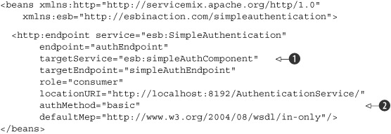
In listing 8.10, we define a target service
![]() pointing to the bean component that we discuss in listing 8.11. Also notice that the role attribute has a value of consumer; you might have expected a provider role since it’s providing a web service endpoint. But instead this says that the HTTP
endpoint is consuming HTTP request messages.
pointing to the bean component that we discuss in listing 8.11. Also notice that the role attribute has a value of consumer; you might have expected a provider role since it’s providing a web service endpoint. But instead this says that the HTTP
endpoint is consuming HTTP request messages.
For our authentication example, the important attribute is the authMethod
![]() . The only available authentication method is basic, but this can be extended to include LDAP and other authentication mechanisms.
The basic authentication implementation will retrieve the HTTP header credentials and authenticate these values against the
default JAAS login module.
. The only available authentication method is basic, but this can be extended to include LDAP and other authentication mechanisms.
The basic authentication implementation will retrieve the HTTP header credentials and authenticate these values against the
default JAAS login module.
The default JAAS login module is configured in the login.properties file in the conf directory of the ServiceMix distribution. There are two modules configured here, as you can see in the following code snippet containing the file’s contents:
servicemix-domain {
  org.apache.servicemix.jbi.security.login.PropertiesLoginModule
    sufficient
    org.apache.servicemix.security.properties.user=
        "users-passwords.properties"
    org.apache.servicemix.security.properties.group="groups.properties";

  org.apache.servicemix.jbi.security.login.CertificatesLoginModule
    sufficient
    org.apache.servicemix.security.certificates.user=
        "users-credentials.properties"
    org.apache.servicemix.security.certificates.group="groups.properties";
};
Because we use a simple username/password combination in the HTTP header of the request message for this example, only the PropertiesLoginModule is relevant. The CertificatesLoginModule is used to process X509 certificates. The PropertiesLogin-Module uses two files to configure the users who have rights for the ServiceMix container: user-passwords.properties and the groups.properties. These files are also in the conf directory, and contain the username/password values (user-passwords.properties) and the groups or role definition (groups.properties). By default, there is only one user, smx, configured that has also smx as a password value. This user is configured to be part of one group (admin).
Now that you’ve seen the JAAS implementation ServiceMix provides and you’ve implemented the HTTP endpoint configuration, we just need to implement the Simple-AuthenticationComponent. Listing 8.11 shows the JBI service component, which will retrieve the authenticated user information from the incoming JBI message.
Listing 8.11. Bean component that logs the security context and the message content

To retrieve the authenticated user information, we must invoke the getSecurity-Subject method on the incoming JBI message
![]() . This will return a javax.security.auth.Subject class instance, where we can retrieve a set of Principal objects.
. This will return a javax.security.auth.Subject class instance, where we can retrieve a set of Principal objects.
Every security aspect is represented by a different Principal object, so the username can be retrieved when we come across a UserPrincipal instance
![]() . The groups where the user is configured as a member can be retrieved when we encounter a GroupPrincipal
. The groups where the user is configured as a member can be retrieved when we encounter a GroupPrincipal
![]() .
.
The message content is logged by using a SourceTransformer to convert the incoming JBI message into a String representation
![]() . Therefore, the bean will log both the security context values and the message content of the incoming JBI message.
. Therefore, the bean will log both the security context values and the message content of the incoming JBI message.
To test the ServiceMix authentication example, you can use the service assembly provided in the resources/chapter8/simpleauth directory. First, you have to start the ServiceMix container with the start target in the ch8-examples.xml Ant file, and then you can use the deploy-simpleauth target in the same build file to build and deploy the authentication service assembly. When the example has been deployed, you can use the Swing test client to send an HTTP request message with the credentials of the smx user. When the authentication example is executed, the console of the Service-Mix container shows the log messages of the smx username and admin group and the message contents.
In addition to the authentication of an HTTP request, we can configure authorization rules in ServiceMix. In the next section you’ll learn how to add authorization to JBI services.
Implementing authorization in ServiceMix
Adding authorization in ServiceMix is simple, so we won’t go through another example but just extend the previous one with an authorization rule. The configuration of authorization rules is based on the group or role definitions defined in the groups.properties file. By default, only one group is defined: the admin group, and it has one member, smx.
The authorization rules can be configured in the security.xml file that is also in the conf directory of the ServiceMix distribution. The part that needs to be configured is the authorizationMap. In the following code snippet, an authorization rule is defined for the SimpleAuthenticationComponent bean that we implement in listing 8.11:
<sm:authorizationMap id="authorizationMap">
  <sm:authorizationEntries>
    <sm:authorizationEntry
        service="*:simpleAuthComponent"
        roles="admin" />
  </sm:authorizationEntries>
</sm:authorizationMap>
Multiple authorization entries can be defined, which link a service to a number of roles. In this example, the simpleAuthComponent JBI service name is linked to the admin role and therefore indirectly to the smx user. The asterisk states that this role definition is applicable to every JBI service with the name of simpleAuthComponent independent of the service namespace.
Before we test this configuration, add another user to the user-passwords.properties file and make this user a member of a new group named users in the group.properties file. We now have two users and only smx is authorized to invoke the bean component that’s part of our simple authentication example. So when you execute the Swing test client again, you should see the same result you got before we defined the authorization rule. But when you change the HTTP credentials in the Swing test client to the just-created user, you’ll receive an error HTTP status code from the ServiceMix container. In the ServiceMix console you’ll see an error message, which means that the bean component hasn’t been invoked due to an authorization failure.
Of course, this is a fairly simple way of configuring authorization rules, but you don’t have to do more in most circumstances. When you want to implement more complex authentication and authorization functionality in ServiceMix, doing so is not too difficult. You can easily implement your own JAAS login module that, for example, will query an LDAP server using the Acegi framework. This login module can then be configured in the login.properties file, and that’s all you have to do to authenticate against an LDAP server. With the knowledge of the JAAS implementation within Service-Mix, you’ll be able to use much more complex security models than the example shown in this section.
The remaining pieces to implementing enterprise quality message flows are transactions. We dealt with error handling in the first section of this chapter, but we didn’t address functionality to roll back database actions or consuming a JMS message from a queue in a transaction. Therefore, we explore transaction functionality in the next section so that you can implement transactional message flows.
8.3. Making your message flows transactional
The ESB is the heart of an integration solution, and therefore topics like error handling and security are important when implementing message flows. What’s missing is the implementation of transactional message flows to ensure the ACID (atomicity, consistency, isolation, and durability) principle inside the ESB.
Atomicity means that the transaction will either perform all tasks of a transaction or none. So all tasks of a transaction will be performed without any exception, or all tasks will not be performed in case of an exception in one of the transaction tasks.
Consistency means that after a transaction has been executed, all resources are in a valid state without violating integrity constraints. This means that the tasks of the transaction are either fully performed without violating any integrity constraints, or the resources are rolled back into the state before the transaction began in the case of any exception or integrity violation.
Isolation means that the tasks performed in a transaction are completely separated from other operations that run on the same resources. So an intermediate state of a transaction shouldn’t be visible to other operations or applications.
The last aspect is durability, which means that when a transaction is successful and the transaction manager has been notified, the transaction can’t be undone. This implies that the transaction result should be available after a system or hardware failure.
When using database systems, the ACID properties are commonly used to ensure the integrity of the content of a database when lots of transactions are being processed. But transactions are also important in the implementation of integration flows. Imagine that a client application sends a JMS message to a queue where a message flow is listening. The message contains an important order that needs to be processed in a database and a back-office application. The message flow will first send a JMS message to the back-office application and then insert the order into the database. If an error occurs when the order is inserted into the database, we don’t want the back-office application to receive the JMS message. If we’d started a transaction at the beginning of the message flow, all the tasks inside this flow would have been rolled back in case of a database exception at the end of the flow.
The following example deals with a special kind of transaction: an XA, or distributed, transaction. Non-XA (local) transactions only deal with a single resource. XA (global) transactions can deal with multiple resources. For distributed transactions, there is a coordinating transaction manager, which uses the Two-Phase Commit (2PC) protocol to be able to coordinate all local transactions. (To learn more about the 2PC protocol, you can look in Wikipedia [http://en.wikipedia.org/wiki/Twophase-commit_protocol] for a detailed description.) In general terms, the 2PC protocol consists of two phases: commit-request and commit. The coordinating transaction manager receives an agreement message from every resource that tries to commit the local transaction. If any agreement message informs the coordinating transaction manager that the local transaction has failed, the whole global transaction is rolled back. If all agreement messages are successful, the coordinating transaction manager instructs the resources to perform a final commit on the local transaction. Figure 8.10 shows an example of an XA transaction with a JDBC and a JCA resource.
Figure 8.10. Example of an XA transaction that involves a JDBC and a JCA resource. In this example, the JCA transaction fails and therefore the global transaction is rolled back.

The example shown in figure 8.10 describes a global transaction with a successful JDBC transaction and a failed JCA transaction. Therefore, the whole transaction is rolled back after the coordinating transaction manager receives the failed agreement message from the JCA local transaction manager. In this section, we explore non-XA transaction examples to understand the basics of transaction handling in Mule and ServiceMix. For XA transaction examples, be sure to check out our website (http://www.esbinaction.com).
To introduce the basics of transaction handling in Mule, let’s look at a local or non-XA transaction. A single resource transaction is the most common type of transaction and also easier to implement. An example of a single resource transaction is a web application that updates information in a database with a JDBC transaction. For message flows, the use of JMS transactions is common to ensure that a message is only consumed when the JMS transaction succeeds. Next we look at the implementation of a single-resource JMS transaction in a Mule configuration.
8.3.1. Implementing transactional message flows in Mule
Implementing transactions in message flow definitions with Mule is not so difficult. There are, however, a few important aspects that you must know before you can work with transactions in Mule. The first thing to notice is that transactions can only be started on inbound endpoints. So when you define an inbound endpoint for a JMS queue, you’re able to define a transaction configuration. The outbound endpoint automatically uses the transaction of the inbound endpoint if one is running. When you’re using a single-resource transaction, this means that the transaction is committed or rolled back after the message is routed to the outbound endpoint. Note that only a few transports support transactions: JMS, JDBC, and VM.
To work with transactions in Mule, we have to know how to start or join a transaction on an inbound endpoint. There are five possible transaction properties that can be set on an inbound endpoint, as shown in table 8.2.
Table 8.2. The transaction properties, which can be configured on inbound endpoints in a Mule configuration
|
Transaction property |
Description |
|---|---|
| NONE | The endpoint will not participate in any transaction. |
| ALWAYS_BEGIN | The endpoint will always start a new transaction. If a transaction already exists, an exception will be thrown. |
| BEGIN_OR_JOIN | The endpoint will start a new transaction if there is no existing transaction, or the endpoint will join the existing transaction. |
| ALWAYS_JOIN | The endpoint will always join the existing transaction. If no transaction exists, an exception will be thrown. |
| JOIN_IF_POSSIBLE | When a transaction exists, the endpoint will join the transaction. If no transaction exists, nothing will be done. |
The best way to learn how to configure transactions within a Mule message flow is to implement a simple example. So let’s start with a single-resource JMS transaction that’s configured on an inbound endpoint.
The example that we implement in this section consumes a message from a JMS queue in a single-resource transaction. When an exception occurs during the processing of the message, in, for example, the Mule component, the transaction should be rolled back and the message should not be removed from the JMS queue. This ensures that the message is only consumed from the JMS queue when the transaction has succeeded and therefore the message processing has succeeded.
But what happens with the message that isn’t consumed from the JMS queue? This message will be redelivered to the same Mule message flow to retry the transaction. To prevent the message from being redelivered over and over again when the transaction fails every time, we configure a maximum number of redeliveries. There is a maximum of six retries in a normal ActiveMQ connection. But we can also configure a different number of maximum retries in the JMS connector definition. After the maximum number of retries has been reached, the message will be sent to a dead letter queue. Let’s look at the Mule configuration of the JMS transaction definition in listing 8.12.
Listing 8.12. Mule configuration with a JMS transaction definition

To use transactions in a Mule message flow definition, we first need to define a transaction factory that Mule will use to
perform the transaction management
![]() . Mule provides a JMS transaction factory by default, and because we’re using a single-resource JMS transaction, this factory
class suits our needs.
. Mule provides a JMS transaction factory by default, and because we’re using a single-resource JMS transaction, this factory
class suits our needs.
As we’ve done in other examples using JMS endpoints, we define a JMS connector. We configure one additional attribute for
the ActiveMQ JMS connector: maxRedelivery
![]() . This attribute configures the maximum number of retries a JMS message will get when the transaction fails. When we don’t
specify a maximum number of retries, the default number of the ActiveMQ connection factory is used (6). Because we want to
reduce the overhead of messages being redelivered, we use a value of 1.
. This attribute configures the maximum number of retries a JMS message will get when the transaction fails. When we don’t
specify a maximum number of retries, the default number of the ActiveMQ connection factory is used (6). Because we want to
reduce the overhead of messages being redelivered, we use a value of 1.
The actual transaction configuration is defined at the inbound endpoint with the transaction element
![]() . We define an action value of ALWAYS_BEGIN, which means that a transaction is always started when a new message is processed from the JMS queue.
. We define an action value of ALWAYS_BEGIN, which means that a transaction is always started when a new message is processed from the JMS queue.
Because we want to test this example with both a successful and a failed transaction, we configure a component that implements this functionality. The Transaction-Service class will fail the transaction when the message content is equal to “bad transaction”; otherwise the transaction will succeed. The following code snippet shows the implementation of the TransactionService:
public class TransactionService {
  public String processMessage(String message) throws Exception {
    if(!"bad transaction".equalsIgnoreCase(message)) {
      return "transaction succeeded";
    } else {
      throw new Exception ("The transaction will fail");
    }
  }
}
When the message content is equal to “bad transaction,” the exception causes the current transaction to fail and the Mule container rolls back the running transaction, which leads to the JMS message not being consumed from the input queue.
We’ve already talked about the dead letter queue, where messages that have reached the maximum number of deliveries are sent. But where can we find this dead letter queue? The dead letter queue is configured in the JMS provider—in our case, ActiveMQ. In the ActiveMQ configuration file activemq.xml, which you can find in the conf directory of the ActiveMQ distribution, you can configure a policy definition that defines the dead letter queue. The following code snippet shows a policy definition that we can use for our JMS transaction example:
<destinationPolicy>
  <policyMap>
    <policyEntries>
      <policyEntry queue=">">
        <deadLetterStrategy>
          <individualDeadLetterStrategy queuePrefix="DLQ." />
        </deadLetterStrategy>
      </policyEntry>
    </policyEntries>
  </policyMap>
</destinationPolicy>
Notice that in the default activemq.xml file, there’s already an example destination-Policy defined. Just overwrite this default destinationPolicy with the one we defined in the code snippet. This code snippet shows a policy entry with a dead letter strategy for all queues (the > notation). For every queue, the dead letter queue will have the same name with a prefix of DLQ. So the dead letter queue name of the transaction.in queue from code listing 8.12 will be DLQ.transaction.in.
With the Mule and ActiveMQ configuration in place, we should now be able to the test the whole example with the TransactionTest JUnit test, which will test both a successful and a failed transaction. To deploy the example to the Mule container, you can use the transaction target in the ch8-examples.xml Ant build script. When you run the JUnit test, you’ll see that a failed transaction will eventually result in a message to the dead letter queue DLQ.transaction.in. You can also use the Swing test client to test the transaction example.
This wraps up our discussion of how to implement transactional message flows in Mule. ServiceMix doesn’t make use of the transactional properties shown in table 8.2 to configure transactions. We look at a new framework called Jencks to provide the transactional functionality in ServiceMix.
8.3.2. Implementing transactional message flows in ServiceMix
The support for transactions in ServiceMix is based on the Java Connector Architecture (JCA) flow implementation in combination with the JMS binding component. By default, ServiceMix uses the Staged Event-Driven Architecture (SEDA) flow implementation to process a message flow. This is also the model that Mule uses by default. But in addition to the SEDA flow model, ServiceMix provides a JMS and JCA model implementation. The differences between these models involve the quality of service support.
The SEDA model is the standard flow implementation that provides support for synchronous and asynchronous messaging. The JMS model adds support for clustering and persistency to the SEDA functionality. And the JCA model only supports asynchronous messaging, but it does provide clustering, persistency, and transactional capabilities. In this section, we focus on the JCA model due to its support for transactional message flows.
To illustrate the implementation of a transactional message flow in ServiceMix, we use an example similar to the Mule example in which we consume a JMS message and forward it to a bean component. The bean component will roll back the transaction if the message content is “bad transaction.” Due to a problem with implementing transactions in a service assembly (namespace conflict with the ActiveMQ Resource Adapter), we implement this example with a stand-alone ServiceMix configuration. This means that we don’t implement a full-service assembly, but we configure the message flow in one file that we also use to start up ServiceMix.
The ServiceMix configuration that we need to define consists of three parts. The first part (listing 8.13) defines the JMS consumer endpoint and the bean component. The second part configures the ActiveMQ broker that we use. The third part configures the transaction manager, the connection manager, and other resources.
Listing 8.13. Part 1 of the transactional message flow with the JMS and bean endpoints

A stand-alone ServiceMix configuration includes a container definition with the container element. Because we want all message exchanges to be transactional, we define the autoEnlistInTransaction attribute
![]() . The container will use the transactionManager bean to manage the transactions
. The container will use the transactionManager bean to manage the transactions
![]() . This transaction manager is defined in listing 8.14. Notice that there are two flow models defined for the container definition: a SEDA and a JCA flow. For the transactional
exchange, the JCA flow will be used by the ServiceMix container.
. This transaction manager is defined in listing 8.14. Notice that there are two flow models defined for the container definition: a SEDA and a JCA flow. For the transactional
exchange, the JCA flow will be used by the ServiceMix container.
The JMS consumer is defined with some extra attributes, which make the JMS consumer transactional
![]() . The JCA message consumer processor is used, and the connection factory, resource adapter, and bootstrap context are configured.
The attribute values refer to the bean definitions (listing 8.14). The connection factory is configured with an XA transaction and therefore the JMS consumer will be transactional.
. The JCA message consumer processor is used, and the connection factory, resource adapter, and bootstrap context are configured.
The attribute values refer to the bean definitions (listing 8.14). The connection factory is configured with an XA transaction and therefore the JMS consumer will be transactional.
Besides the JMS consumer, we define the bean component, which will process the incoming JMS message. The bean component is implemented with a simple Spring bean, which will roll back the transaction if the message content is equal to “bad transaction.”
The message flow definition is quite simple, as you saw in listing 8.13. The transactional behavior is implemented in the second part of the transactional message flow example. The configuration shown in listing 8.14 uses the Jencks framework to provide a transactional connection factory and manager.
Listing 8.14. Part 2 of the transactional message flow with the connection definition

Listing 8.14 uses the Jencks framework and the ActiveMQ Resource Adapter (RA). These managers are already configured in ServiceMix by default, so we can import the tx.xml and jndi.xml file. We also have to import the security.xml file and define the servicemix.properties file, because the configuration in these files is used in jndi.xml.
The resource adapter definition specifies the JMS connection used to connect to the ActiveMQ broker
![]() . In the serverURL definition of the JMS connection, we can also specify the redelivery policy to be used. In our example, we specify a maximum
number of redeliveries that will be processed before the JMS message will be sent to the configured dead letter queue. The
configuration of the dead letter queue is defined in the ActiveMQ broker configuration that we discuss in listing 8.15.
. In the serverURL definition of the JMS connection, we can also specify the redelivery policy to be used. In our example, we specify a maximum
number of redeliveries that will be processed before the JMS message will be sent to the configured dead letter queue. The
configuration of the dead letter queue is defined in the ActiveMQ broker configuration that we discuss in listing 8.15.
The connection factory used in the JMS consumer definition in listing 8.14 indirectly uses the resource adapter definition
![]() . The Jencks connection factory uses the managed connection factory defined with the ActiveMQ RA framework, which uses the
resource adapter definition. The ActiveMQ connection is managed by the Jencks connection manager (which we discuss in a moment).
. The Jencks connection factory uses the managed connection factory defined with the ActiveMQ RA framework, which uses the
resource adapter definition. The ActiveMQ connection is managed by the Jencks connection manager (which we discuss in a moment).
The one part remaining is the ActiveMQ broker configuration. Because we use the stand-alone ServiceMix configuration, ServiceMix won’t be started with the configuration specified in the conf directory of the ServiceMix distribution. Therefore, the ActiveMQ broker won’t be started without a broker configuration in our transactional message flow definition. Listing 8.15 shows part 3 of the transactional message flow example.
Listing 8.15. Part 3 of the transactional message flow with ActiveMQ broker definition
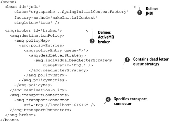
Besides the ActiveMQ broker definition, we need to configure the JNDI bean to be able to start the stand-alone ServiceMix
container correctly
![]() .
.
The ActiveMQ broker configuration starts with the broker element
![]() , which is also referenced in the ServiceMix container configuration in listing 8.13. The broker configuration is similar to the activemq.xml file content in the conf directory of the ServiceMix distribution.
This ActiveMQ configuration example is kept simple, but you can extend this configuration with, say, a persistency configuration.
, which is also referenced in the ServiceMix container configuration in listing 8.13. The broker configuration is similar to the activemq.xml file content in the conf directory of the ServiceMix distribution.
This ActiveMQ configuration example is kept simple, but you can extend this configuration with, say, a persistency configuration.
Because we want to show a successful and a failed transaction, we include a dead letter queue strategy configuration
![]() . A failed transaction causes the JMS message to be redelivered to the JMS consumer again. After the message has been redelivered
two times, the message will be sent to a dead letter queue (according to the maximum redeliveries setting in listing 8.14). With this dead letter strategy, we specify that every queue has a corresponding dead letter queue with the same queue name
prefixed by the DLQ queue prefix.
. A failed transaction causes the JMS message to be redelivered to the JMS consumer again. After the message has been redelivered
two times, the message will be sent to a dead letter queue (according to the maximum redeliveries setting in listing 8.14). With this dead letter strategy, we specify that every queue has a corresponding dead letter queue with the same queue name
prefixed by the DLQ queue prefix.
The last part of the ActiveMQ broker configuration defines the transport connector that will be used for the ActiveMQ broker
![]() . Because we don’t have specific needs for the transactional message flow implementation, we use the default TCP transport
connector.
. Because we don’t have specific needs for the transactional message flow implementation, we use the default TCP transport
connector.
To test the transactional message flow configuration, you can use the servicemix.xml file available in the resources/chapter8/transaction-single/servicemix directory. To start the example, first execute the deploy-transaction target in the ch8-examples.xml Ant build file. This Ant target copies the TransactionComponent class in a transaction-example.jar file to the lib directory of the ServiceMix distribution. Furthermore, the Ant target extracts the libraries of the JMS BC, the Bean SE and a ServiceMix shared JBI component to the lib directory of ServiceMix. Because we run this example with a static configuration, we need these libraries in the lib directory of ServiceMix. To start up the ServiceMix container with the transaction example, you can use the following command script:
Windows:
%SERVICEMIX_HOME%/bin/servicemix.bat servicemix/servicemix.xml
Unix:
$SERVICEMIX_HOME/bin/servicemix.sh servicemix/servicemix.xml
When the ServiceMix container is started, you can use the Swing test client to send a message that will result in a successful transaction (with a started message content); any other message content will cause the transaction to roll back.
8.4. Summary
In this chapter you learned how to implement enterprise-quality message flows that are suited for real-life integration projects. Mule provides a number of exception strategies designed to handle errors at various points of a message flow. With the default and custom exception strategies, you can implement a fine-grained error-handling solution to meet your needs. ServiceMix doesn’t provide a lot of error-handling capabilities besides the default MEP implementation. For in-out message exchanges, this means that fault messages are returned to the client application, but for in-only message exchanges this results in an exception that will stop the processing of the message flow. But with the addition of the Camel framework, errors can be easily managed in ServiceMix.
We also looked at how to implement security in your message flow. You saw that Mule nicely integrates with Acegi and therefore can leverage all the functionality that Acegi provides for authentication and authorization. Notice that Mule can also use JAAS to implement authentication and authorization functionality. It’s quite easy to use authentication and authorization with an LDAP server. ServiceMix relies on JAAS for its authentication and authorization capabilities. The out-of-the-box functionality uses files to define users and groups or roles. You can easily implement an HTTP message flow with authentication and authorization capabilities.
We also showed you how to use JMS transactions in both Mule and ServiceMix message flows. You are now able to implement a transactional message flow with a JMS consumer and a bean component in both Mule and ServiceMix.
With the knowledge gained while reading this chapter, you’re ready to start with the implementation of larger examples or case studies. Until now we’ve shown the functionality of open source ESBs with reasonably short examples, but in real life you’ll be confronted with more complex situations. Therefore, we’ll implement case studies that meet the complexity of real-life projects. In chapter 9 we discuss the full lifecycle of an integration project, from design to deployment. We use the Enterprise Integration patterns of Hohpe and Woolf to be able to create simple design models that provide much insight into the integration solution. You are just a few pages away from learning about a lightweight and fun way to implement integration solution.