Chapter 8. DSL Packaging and Deployment
So far, we’ve developed a series of abstract syntax models, diagrams, and model transformations. After creating a collection of domain-specific language (DSL)-related artifacts, a Toolsmith needs to test and deploy them to a Practitioner’s workbench. In this chapter, we explore polishing items, packaging, and deployment options for these artifacts.
Although this book does not cover the topic, it should become obvious that much of the code you create to deploy DSLs could be generated from yet another DSL defined to model the aspects of deployment (not to mention building and packaging aspects). Feature definition, user interface plug-in, transformation invocation actions, and so on are all potential targets for a set of code-generation templates and corresponding models. When it comes to product lines, the information captured to select variation points and options for generating a set of plug-ins that represent a product are ideally captured in models and leveraged in this manner.
8.1 Deployment Preparation
Before deployment, you must tie up all loose ends. Up to this point, we’ve been developing our collection of requirements DSLs in a development workspace and testing in a runtime instance with all plug-ins. Let’s look at a number of checklist items to make sure our DSLs are generated consistently, in preparation for feature and product definition.
8.1.1 Artwork
The most impactful thing we can do at this point is add icons and other artwork to the diagram, edit, and editor plug-ins we’ve generated. The default generated icons do little to convey meaning, so we can replace them with ones that do—or just remove them altogether. Remember, just because we can add icons doesn’t mean we should.
I’m not a graphic artist, so let’s look for another source of icons. Thousands of icons ship with Eclipse, so we can try to reuse these, although I don’t recommend this for a real product. Before plug-ins were bundled in .jar files, it was simple to see all the icons that shipped with Eclipse. It’s still easy to do with a simple Ant script that extracts all *.gif images from each of the **/*.jar files in the plug-ins directory. Start with a complete install of all Eclipse projects, and then prepare to scroll through thousands of icons in your file browser.
After collecting some candidate icons, we begin to replace those found in our generated plug-in projects. This is most easily accomplished by simply renaming your new icons to match the names found in the /icons/full/obj16/ directory (or similar directory). Most diagram element icons are found in their corresponding *.model.edit plug-in, and the Diagram Wizard icon is found in the *.diagram plug-in. In the case of our Requirements editor, we need to replace the image in its EMF-generated *.editor plug-in. This gets us close, but some missing ones still will require path information to be entered into our models. It’s a good idea to back up the plug-in icon directories at this point, to avoid losing them upon regeneration.
Reference-based links in our diagrams are missing icons because they do not correspond to a domain model class element, as is the case with our Mindmap subtopic link. To specify the icon to use for the subtopic link, we can open the mindmap.gmftool model and navigate to our Subtopic Creation Tool. The tooling model wizard adds a large and small Default Image element to each creation tool, which normally points to the corresponding *.edit plug-in icon. We can delete these children from our Subtopic tool and create a new Small Icon Bundle Image. For the Bundle property, we can point to our org.eclipse.mindmap.model.edit plug-in and specify icons/full/obj16/Subtopic.gif for the Path property. Of course, we need to add this image to the *.edit plug-in because it was not provided. After this, we can recreate the mindmap.gmfgen model from the mindmap.gmfmap model and regenerate the Mindmap diagram. You’ll find the new icon used in the palette, which just leaves updating the remainder of the tooling models for similar cases.
You won’t go this far in the sample projects, but consider adding several other artwork items to your Eclipse-based product. Welcome pages, splash images, about dialog images, and more are all possibilities. Look to the branding topic in the Eclipse help system to find out more information on providing additional polish to your application.
8.1.2 Developing a User Interface Plug-In
We’ve tested our diagrams in the runtime workbench and our transformations in the development workbench using dynamic instance models. Now we can create an org.eclipse.requirements.ui plug-in that will give us a place to define a Requirements perspective, a project wizard, and the actions and object contributions we need to allow Practitioners to invoke them on their artifacts.
Wizard and Perspective
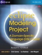
Using the New → Plug-in Project wizard, create an empty org.eclipse.requirements.ui plug-in in your workspace. In the Extensions page of the plug-in manifest editor, create a new contribution to the org.eclipse.ui.newWizards extension-point. Add a category to this contribution with an ID of org.eclipse.requirements.wizards.category. We use this ID later to unite our generated editor wizards under a common category in the New dialog. Now add the wizard element and name it Requirements Project Wizard with an ID of org.eclipse.requirements.ui.wizards.id. Complete the rest of the contribution to match the following—note that it specifies a Requirements perspective that we define next.
Using the helper in the editor, or by manually entering into the plugin.xml tab itself, contribute the following to the org.eclipse.ui.perspectives and perspectiveExtensions extension-points.

We’ve specified a RequirementsProjectWizard and a Requirements-Perspective in our manifest that we need to implement. The implementations for each class are not covered here, but are provided in the sample projects. Consult the Eclipse help system for additional information on wizards and perspectives; their details fall outside the scope of this book. The important information required is the wizard category ID that we can use with our generator models in Section 8.1.1, “Generation Models.”
Preferences
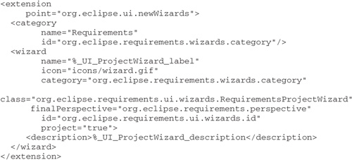
Our generated diagram preferences are each given their own root in the Preferences dialog, but we want them all to fall under a general Requirements category that will eventually contain more general preferences. To provide a common category each diagram can leverage, we’ll define a contribution to the org.eclipse.ui.preferencePages extension-point as follows.
We can use the Quick Fix to have a default implementation provided for our RequirementsGeneralPreferencePage class, with the important item currently being the creation of the preference category ID.
Actions
We now have a new perspective and project type for our Requirements product, along with its four editors and corresponding creation wizard. But we don’t have a way for the Practitioner to invoke the various transformations defined by the Toolsmith on each of the instance models that will be created. For this, we can provide action contributions to invoke the QVT Operational Mapping Language (QVTO) and Xpand templates on the various artifacts.
The sample projects contain actions to invoke each of our transformations, although we can improve these a bit. At the time of this writing, QVTO scripts are not yet available to be invoked by the Modeling Workflow Engine. The chaining of transformations is a common use case that we could work into our Java code, although we prefer to define it in a workflow. Furthermore, the current action to invoke a QVTO transformation simply uses the standard launch configuration in a dialog. The most awkward part of the process is that QVTO expects the root element of the file we invoke the action upon to be its input model. In the case of diagrams that are persisted in the same file as the domain model, this means simply picking the proper element within the file using the dialog. Still, it could be all done without user intervention, beyond selecting the input model and specifying the output location.

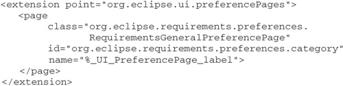
This is the action code to invoke the mindmap2requirements transformation:


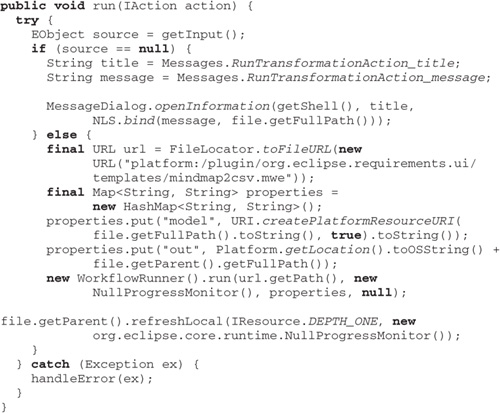
The action used to invoke a workflow for Model-to-Text Transformation (M2T) is largely the same. The following run() method is an example of how the two differ.
8.1.3 Generation Models
Let’s revisit each of our generation models, to examine the options we might have overlooked during development and leverage our new UI plug-in.
We’ve seen that GMF can persist models and diagrams in either separate files or just one. For our application, we don’t need several diagrams on a single large model instance, so we’ll set the Same File for Diagram and Model property in the Gen Editor Generator element to true for all *.gmfgen models. Also in this element is the Copyright Text property, which we populate with the appropriate statement. Likewise, in each EMF *.genmodel file, we enter the statement in its Copyright Text property of the root element. Note that copyright statements are output only on initial generation, forcing a delete and regeneration of our existing code. We don’t necessarily need to do this for our samples because they contain modified code that would need to be preserved and restored after regeneration.
In the Gen Plugin element for each diagram, we set the Name property and Provider appropriately—in this case, a friendly name for each plug-in and Eclipse.org for the provider. We also set Printing Enabled to true because it’s not enabled by default. For the Version property, we leave the default 1.0.0.qualifier value because the qualifier suffix will be replaced by a time stamp during export and, eventually, during our headless PDE build.
By default, Graphical Modeling Framework (GMF) places its generated new diagram wizards in the Examples category. We want each of our requirements editors to fall under our new requirements category, so we can modify the diagram .gmfgen models to specify org.eclipse.requirements.wizards.category for the Gen Diagram element’s Creation Wizard Category ID property, found in the Editor category. Eclipse Modeling Framework (EMF), on the other hand, places its generated creation wizards in its own Example EMF Model Creation Wizards category with the ID org.eclipse.emf.ecore.wizard.category.ID. Unfortunately, the EMF genmodel provides only a Boolean property either to generate a wizard or not, with no property to specify the category it should fall under. We don’t expect to change it often, and because EMF does not overwrite plug-in manifest files upon regeneration, we can make the change in the generated org.eclipse.requirements.model.editor/plugin.xml file. Delete the nested category element from the *.newWizards contribution and change the wizard element’s category attribute to org.eclipse.requirements.wizards.category.
We created a general preference category for our Requirements product that we now need to leverage in our generated diagram preferences. Unfortunately, the Gen Standard Preference Page element in the GMF generator model does not enable us to specify the parent category. We can produce a decorator model and custom templates to provide a generated approach, or we can simply add to each generated plug-in manifest the org.eclipse.requirements.preferences.category ID as the root page’s category. After doing so, we see each diagram preferences under a common Requirements group, as shown in Figure 8-1.
Finally, not all string values can be adjusted in the generator model. This forces us to make final polish tweaks to the message.properties file in our generated diagram. For example, our color modeling diagram is called dnc Diagram in our new diagram wizard. Many of the default namings come from the underlying domain model—in this case, our dnc package. After using these and some other polishing items, we’re ready to specify a product definition and export it for testing and use.
Figure 8-1 Requirements preferences

8.2 Defining a Product
Using the Product Definition Wizard and associated Help content, we can configure a requirements.product to use for deploying our product for multiple platforms. We first configure a minimal launch configuration that includes only those required and use it to configure the product itself. Be careful when selecting required plug-ins: The PDE’s Add Required Plug-ins feature does not always detect all runtime requirements.
We need to download and install the RCP delta pack into our target, to ensure that we have the different platform launch files available. When this is complete, we can build our product bundles from the Product Definition editor and test on the required platforms.
Another option to building a product is to look at Amalgam’s release engineering builder, which comes as another example in the DSL Toolkit. The DSL Toolkit itself is built using this method, which begins by defining a build model to account for the parameters required to generate build scripts from a related product model. This model-driven build approach is in its beginning stages, so I do not discuss this in detail at this point. The PDE’s build templates could someday be Xpand templates, and the entire build process could be driven by a simple configuration model for each project or component.
8.2.1 Deploying Source
One of the reasons I chose to use a Plug-in Project type for our DSLs will now become apparent. As you know, the Plug-ins view in Eclipse lets you import any plug-in into your workspace. If the plug-in was packaged with source code, you can import the plug-in into your workspace in a condition to continue development. We can apply the same concept to working with DSLs. If we properly configure our DSL projects for deployment, clients can import the source of the deployed DSL into their workspace; modify the domain model, templates, diagram definition, and so on; and regenerate the plug-ins to provide an update.
8.3 Summary
In this chapter, we touched upon the most basic packaging elements to consider when creating a product for your DSL. Many additional enhancements and usability issues will need to be resolved, though fall outside the scope of this book. This concludes the hands-on portion of the book.