Chapter 12
Networks and Communications
To guard against the baneful influence exerted by strangers is therefore an elementary dictate of savage prudence. Hence before strangers are allowed to enter a district, or at least before they are permitted to mingle freely with the inhabitants, certain ceremonies are often performed by the natives of the country for the purpose of disarming the strangers of their magical powers, or of disinfecting, so to speak, the tainted atmosphere by which they are supposed to be surrounded.
—The Golden Bough, Sir James George Frazer
Learning Objectives
After studying this chapter, you should be able to:
List and define the key functions that a network management system should include.
Give an overview of a network management system and explain each of its key components.
Explain the role of firewalls as part of a computer and network security strategy.
List the key characteristics of firewalls.
Understand the security considerations for various aspects of network management.
Understand the security considerations for various aspects of electronic communication.
Present an overview of network and communications best practices.
This chapter provides a survey of security and security management issues related to two broad and related topics: networks and electronic communications. The chapter begins with an overview of network management concepts. Following this are sections covering firewalls and virtual private networks. With this background, the chapter then addresses the specific security concerns involved with network management. Next, the chapter examines electronic communications in the enterprise environment, including email, instant messaging, voice over IP networks, and telephony and conferencing.
12.1 Network Management Concepts
This section provides an overview of network management. Let’s begin by looking at the requirements for network management. This will provide an idea of the scope of the task to be accomplished. To manage a network, it is fundamental to know something about the current status and behavior of that network.
Effective management requires a network management system that includes a comprehensive set of data gathering and control tools and that is integrated with the network hardware and software. Let’s look at the general architecture of a network management system.
Network Management Functions
Table 12.1 lists key functions of network management, as suggested by the International Organization for Standardization (ISO) in ISO 7498-4, Open Systems Interconnection—Basic Reference Model—Part 4: Management Framework. A much more detailed description of these network management functions is contained in ITU-T (International Telecommunication Union Telecommunication Standardization Sector) M.3400, Telecommunications Management Functions. These categories provide a useful way of organizing this discussion of requirements.
TABLE 12.1 ISO Management Functional Areas
Category |
Description |
|---|---|
Fault management |
The facilities that enable the detection, isolation, and correction of abnormal operation of the Open Systems Interconnection (OSI) environment |
Accounting management |
The facilities that enable charges to be established for the use of managed objects and costs to be identified for the use of those managed objects |
Configuration management |
The facilities that exercise control over, identify, collect data from, and provide data to managed objects for the purpose of assisting in providing for continuous operation of interconnection services |
Performance management |
The facilities needed to evaluate the behavior of managed objects and the effectiveness of communication activities |
Security management |
The aspects of security essential to operate OSI network management correctly and to protect managed objects |
Fault Management
To maintain proper operation of a complex network, make sure that systems as a whole, as well as each essential component individually, are in proper working order. When a fault occurs, it is important to do the following as rapidly as possible:
Determine exactly where the fault is
Isolate the rest of the network from the failure so it continues to function without interference
Reconfigure or modify the network in such a way as to minimize the impact of operation without the failed component or components
Repair or replace the failed components to restore the network to its initial state
Central to the definition of fault management is the fundamental concept of a fault, as distinguished from an error. A fault is an abnormal condition that causes a device or system component to fail to perform in a required manner and that requires management attention (or action) for repair. A fault is usually indicated by failure to operate correctly or by excessive errors. For example, if a communications line is physically cut, no signals get through. Or a crimp in the cable can cause wild distortions so that there is a persistently high bit error rate. Certain errors (for example, a single bit error on a communication line) can occur occasionally and are not normally considered to be faults. It is usually possible to compensate for errors using the error control mechanisms of the various protocols.
Users expect fast and reliable problem resolution. Most end users tolerate occasional outages. When these infrequent outages do occur, however, users generally expect to receive immediate notification and expect the problem be corrected almost immediately. Providing such a level of fault resolution requires very rapid and reliable fault detection and diagnostic management functions. The impact and duration of faults are also minimized by the use of redundant components and alternate communication routes, to give the network a degree of fault tolerance. An organization should make sure the fault management capability is redundant to increase network reliability.
Users expect to be kept informed of the network status, including both scheduled and unscheduled disruptive maintenance. Users expect reassurance of correct network operation through mechanisms that use confidence tests or that analyze dumps, logs, alerts, or statistics. After correcting a fault and restoring a system to its full operational state, the fault management service must ensure that the problem is truly resolved and that no new problems are introduced. This requirement is called problem tracking and control.
To satisfy requirements, fault management generally includes functions to do the following:
Maintain and examine error logs
Accept and act upon error detection notifications
Trace and identify faults
Carry out sequences of diagnostic tests
Correct faults
As with other areas of network management, fault management should have minimal effect on network performance.
Accounting Management
In many enterprise networks, individual divisions or cost centers, or even individual project accounts, are charged for the use of network services. These are internal accounting procedures rather than actual cash transfers, but they are important to the participating users nevertheless. Furthermore, even if no such internal charging is employed, a network manager needs to be able to track the use of network resources by user or user class for a number of reasons, including the following:
A user or group of users may abuse their access privileges and burden the network at the expense of other users.
Users can make inefficient use of the network, and the network manager can assist in changing procedures to improve performance.
The network manager is in a better position to plan for network growth if user activity is known in sufficient detail.
A network manager must specify the kinds of accounting information to be recorded at various nodes, the desired interval between successive transmissions of the recorded information to higher-level management nodes, and the algorithms used in calculating the charging.
To limit access to accounting information, the accounting facility must provide the capability to verify users’ authorization to access and manipulate that information.
To satisfy requirements, accounting management generally includes functions to do the following:
Inform users of costs incurred or resources consumed
Enable accounting limits to be set and tariff schedules to be associated with the use of resources
Enable costs to be combined where multiple resources are invoked to achieve a given communication objective
Configuration Management
Modern data communication networks are composed of individual components and logical subsystems (for example, the device driver in an operating system) that are configured to perform many different applications. The same device, for example, can be configured to act either as a router or as an end system node or both. Once it is decided how a device is to be used, the configuration manager chooses the appropriate software and set of attributes and values (for example, a transport layer retransmission timer) for that device.
Configuration management is concerned with initializing a network and gracefully shutting down part or all of the network. It is also concerned with maintaining, adding, and updating the relationships among components and the status of components during network operation.
Startup and shutdown operations on a network are part of configuration management. It is often desirable for these operations on certain components to be performed unattended (for example, starting up or shutting down a network interface unit). A network manager needs to be able to identify initially the components that comprise the network and to define the desired connectivity of those components. Those who regularly configure a network with the same or a similar set of resource attributes need ways to define and modify default attributes and to load those predefined sets of attributes into the specified network components. A network manager needs to be able to change the connectivity of network components when users’ needs change. Reconfiguration of a network is often desired in response to performance evaluation or in support of network upgrade, fault recovery, or security checks.
Users often need to, or want to, be informed of the status of network resources and components. Therefore, when changes in configuration occur, the network or system manager should notify users of these changes. The network or system manager should also generate configuration reports either on some routine periodic basis or in response to a request for such a report. Before reconfiguration, users often want to inquire about the upcoming status of resources and their attributes.
Network managers usually want only authorized users (operators) to manage and control network operation (for example, software distribution and updating).
To satisfy requirements, configuration management generally includes functions to do the following:
Set the parameters that control the routine operation of the system
Associate names with managed objects and sets of managed objects
Initialize and close down managed objects
Collect information on demand about the current condition of the system
Obtain announcements of significant changes in the condition of the system
Change the configuration of the system
Performance Management
Modern data communications networks are composed of many and varied components, which must intercommunicate and share data and resources. In some cases, it is critical to the effectiveness of an application that the communication over the network be within certain performance limits. Performance management of a computer network comprises two broad functional categories: monitoring and controlling. Monitoring is the function that tracks activities on the network. The controlling function enables performance management to make adjustments to improve network performance. Some of the performance issues of concern to a network manager are as follows:
What is the level of capacity utilization?
Is there excessive traffic?
Has throughput been reduced to unacceptable levels?
Are there bottlenecks?
Is response time increasing?
To deal with these concerns, a network manager must focus on some initial set of resources to be monitored to assess performance levels. This includes associating appropriate metrics and values with relevant network resources as indicators of different levels of performance. For example, what count of retransmissions on a transport connection is considered to be a performance problem requiring attention? Performance management, therefore, must monitor many resources to provide information in determining network operating level. By collecting this information, analyzing it, and then using the resultant analysis as feedback to the prescribed set of values, a network manager becomes more and more adept at recognizing situations that indicate present or impending performance degradation.
Before using a network for a particular application, a user may want to know such things as the average and worst-case response times and the reliability of network services. Thus, performance must be known in sufficient detail to respond to specific user queries. End users expect network services to be managed in such a way as to afford their applications consistently good response time.
Network managers need performance statistics to help them plan, manage, and maintain large networks. Performance statistics are used to recognize potential bottlenecks before they cause problems to end users. They also enable network managers to take appropriate corrective action. This action either takes the form of changing routing tables to balance or redistribute traffic load during times of peak use or when a bottleneck is identified by a rapidly growing load in one area. Over the long term, capacity planning based on such performance information indicates the proper decisions to make, for example, with regard to expansion of lines in that area.
To satisfy requirements, performance management generally includes functions to do the following:
Gather statistical information
Maintain and examine logs of system state histories
Determine system performance under natural and artificial conditions
Alter system modes of operation for the purpose of conducting performance management activities
Security Management
Security management is concerned with generating, distributing, and storing encryption keys. Passwords and other authorization or access control information must be maintained and distributed. Security management is also concerned with monitoring and controlling access to computer networks and access to all or part of the network management information obtained from the network nodes. Logs are an important security tool, and therefore security management is very much involved with the collection, storage, and examination of audit records and security logs, as well as with the enabling and disabling of these logging facilities.
Security management provides facilities for protection of network resources and user information. Network security facilities should be available for authorized users only. Users want to know that the proper security policies are in force and effective and that the management of security facilities is itself secure.
The purpose of security management is to support the application of security policies by means of functions that include the following:
The creation, deletion, and control of security services and mechanisms
The distribution of security-related information
The reporting of security-related events
Network Management Systems
A large network cannot be put together and managed by human effort alone. The complexity of such a system dictates the use of automated network management tools. The urgency of the need for such tools is increased, and the difficulty of supplying such tools is also increased, if the network includes equipment from multiple vendors. Moreover, the increasing decentralization of network services, as exemplified by the increasing importance of workstations and client/server computing, makes coherent and coordinated network management increasingly difficult. In such complex information systems, many significant network assets are dispersed far from network management personnel.
Components of a Network Management System
A network management system is a collection of tools for network monitoring and control that is integrated in the following senses:
A single operator interface with a powerful but user-friendly set of commands for performing most or all network management tasks
A minimal amount of separate equipment, as most of the hardware and software required for network management is incorporated into the existing user equipment
A network management system consists of incremental hardware and software additions implemented among existing network components. The software used in accomplishing the network management tasks resides in the host computers and communications processors (for example, front-end processors, terminal cluster controllers, switches, routers). A network management system is designed to view the entire network as a unified architecture, with addresses and labels assigned to each point and the specific attributes of each element and link known to the system. The active elements of the network provide regular feedback of status information to the network control center. In this context, the term element refers to network devices and end systems attached to the network.
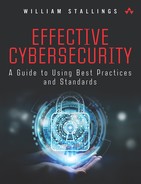
Figure 12.1 suggests the principal components of a network management system. Each network node contains a collection of software devoted to the network management task, referred to in the diagram as a network management entity (NME).
Each NME performs the following tasks:
Collects statistics on communications and network-related activities
Stores statistics locally
Responds to commands from the network control center, including commands to do the following:
Transmit collected statistics to the network control center
Change a parameter (for example, a timer used in a transport protocol)
Provide status information (for example, parameter values, active links)
Generate artificial traffic to perform a test
Sends messages to the NCC when local conditions undergo significant changes
At least one host in the network is designated as the network control host, or manager. In addition to the NME software, the network control host includes a collection of software called the network management application (NMA). The NMA includes an operator interface to allow an authorized user to manage the network. The NMA responds to user commands by displaying information and/or by issuing commands to NMEs throughout the network. This communication is carried out using an application-level network management protocol that employs the communications architecture in the same fashion as any other distributed application.
Every other node in the network that is part of the network management system includes an NME and, for purposes of network management, is referred to as an agent. Agents include end systems that support user applications as well as nodes that provide a communications service, such as front-end processors, cluster controllers, bridges, and routers.
As depicted in Figure 12.1, the network control host communicates with and controls the NMEs in other systems. For maintaining high availability of the network management function, two or more network control hosts are used. In normal operation, one of the hosts is actively used for control, while the others are idle or simply collecting statistics. If the primary network control host fails, the backup system is used.
Distributed Network Management Systems
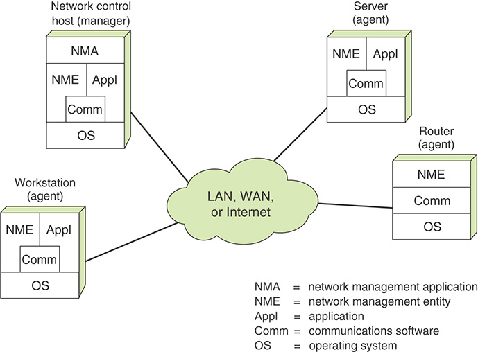
In a traditional centralized network management scheme, one host in the configuration has the role of a network management station; there can be one or two other management stations in a backup role. The remainder of the devices on the network contain agent software and a local database to allow monitoring and control from the management station. As networks grow in size and traffic load, such a centralized system is unworkable. Too much burden is placed on the management station, and there is too much traffic, with reports from every single agent having to wend their way across the entire network to headquarters. In such circumstances, a decentralized, distributed approach works best (see the example in Figure 12.2). In a decentralized network management scheme, there can be multiple top-level management stations, which are referred to as management servers. Each such server can directly manage a portion of the total pool of agents. However, for many of the agents, the management server delegates responsibility to an intermediate manager. The intermediate manager plays the role of manager to monitor and control the agents under its responsibility. It also plays an agent role to provide information and accept control from a higher-level management server. This type of arrangement spreads the processing burden and reduces total network traffic.
Network Management Architecture
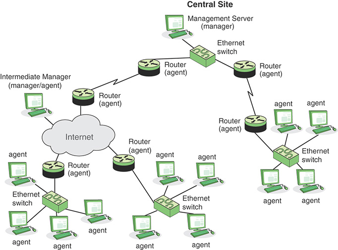
Cisco has developed a hierarchical network management architecture [CISC07] based on ITU M.3400, as shown in Figure 12.3.
The element management layer provides an interface to the network devices and communications links in order to monitor and control them. This layer captures events and fault occurrences through a combination of direct polling and unsolicited notification by network elements. Management function modules provide interfaces to specific elements, allowing elements from different manufacturers to be incorporated under a single network management system.
The network management layer (NML) provides a level of abstraction that does not depend on the details of specific elements. In terms of event management, this layer takes input from multiple elements (which in reality can be different applications), correlates the information received from the various sources (also referred to as root-cause analysis), and identifies the event that occurred. The NML provides a level of abstraction above the element management layer in that operations personnel are not “weeding” through potentially hundreds of unreachable or node down alerts but instead are focusing on the actual event, such as failure of an area-border router. Thus, this layer performs a filtering function, only providing a more aggregated view of the network through a common database across all five functions as well as a trouble ticketing facility.
The service management layer is responsible for adding intelligence and automation to filtered events, event correlation, and communication between databases and incident management systems. The goal is to move traditional network management environments and the operations personnel from element management (managing individual alerts) to network management (managing network events) to service management (managing identified problems).
12.2 Firewalls
The firewall is an important complement to host-based security services such as intrusion detection systems. Typically, a firewall is inserted between the premises network and the Internet to establish a controlled link and to erect an outer security wall or perimeter. The aim of this perimeter is to protect the premises network from Internet-based attacks and to provide a single choke point where security and auditing are imposed. Firewalls are also deployed internally in an enterprise network to segregate portions of the network.
A firewall provides an additional layer of defense, insulating internal systems from external networks or other parts of the internal network. This follows the classic military doctrine of “defense in depth,” which is applicable to IT security.
Firewall Characteristics
“Network Firewalls” [BELL94] lists the following design goals for a firewall:
All traffic from inside to outside, and vice versa, must pass through the firewall. This is achieved by physically blocking all access to the local network except via the firewall. Various configurations are possible, as explained later in this chapter.
Only authorized traffic, as defined by the local security policy, is allowed to pass. Various types of firewalls are used, and they implement various types of security policies, as explained later in this chapter.
The firewall itself is immune to penetration. This implies the use of a hardened system with a secured operating system. Trusted computer systems are suitable for hosting a firewall and often required in government applications.
In general terms, firewalls use four techniques that to control access and enforce the site’s security policy. Originally, firewalls focused primarily on service control, but they have since evolved to provide all four techniques:
Service control: Determines the types of Internet services that can be accessed—inbound or outbound. The firewall can filter traffic on the basis of IP address, protocol, or port number; provide proxy software that receives and interprets each service request before passing it on; or host the server software itself, such as a web or mail service.
Direction control: Determines the direction in which particular service requests are initiated and allowed to flow through the firewall.
User control: Controls access to a service according to which user is attempting to access it. This feature is typically applied to users inside the firewall perimeter (local users). It can also be applied to incoming traffic from external users, though this requires some form of secure authentication technology, such as that provided in IP Security (IPsec).
Behavior control: Controls how particular services are used. For example, the firewall can filter email to eliminate spam or enable external access to only a portion of the information on a local web server.
Before proceeding to the details of firewall types and configurations, let’s consider the capabilities that are within the scope of a firewall:
A firewall defines a single choke point that keeps unauthorized users out of the protected network, prohibits potentially vulnerable services from entering or leaving the network, and provides protection against various kinds of IP spoofing and routing attacks. The use of a single choke point simplifies security management because security capabilities are consolidated on a single system or set of systems.
A firewall provides a location for monitoring security-related events. Audits and alarms are implemented on the firewall system.
A firewall is a convenient platform for several Internet functions that are not security related. These include a network address translator, which maps local addresses to Internet addresses, and a network management function, which audits or logs Internet usage.
A firewall serves as a platform for implementing virtual private networks (as discussed in the following section).
Firewalls have limitations, including the following:
A firewall cannot protect against attacks that bypass the firewall. Internal systems can have dial-out capability to connect to an ISP. An internal LAN can support a modem pool that provides dial-in capability for traveling employees and telecommuters.
A firewall does not fully protect against internal threats, such as disgruntled employees or employees who unwittingly cooperate with external attackers.
An improperly secured wireless LAN can be accessed from outside the organization. An internal firewall that separates portions of an enterprise network does not guard against wireless communications between local systems on different sides of the internal firewall.
A laptop, PDA, or portable storage device can be used and infected outside the corporate network and then attached and used internally.
Types of Firewalls
A firewall acts as a packet filter. It operates as a positive filter, allowing only packets that meet specific criteria, or as a negative filter, rejecting any packet that meets certain criteria. Depending on the type, a firewall can examine one or more protocol headers in each packet, the payload of each packet, or the pattern generated by a sequence of packets. This section looks at the principal types of firewalls, shown in Figure 12.4.
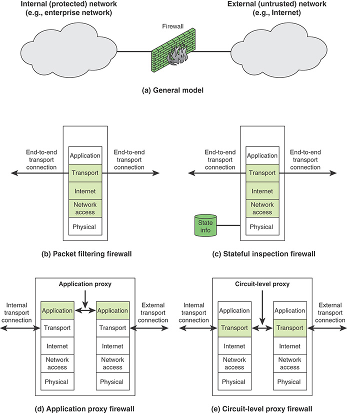
Packet Filtering Firewall
A packet filtering firewall applies a set of rules to each incoming and outgoing Internet Protocol (IP) packet and then forwards or discards the packet (see Figure 12.4b). This type of firewall is typically configured to filter packets going in both directions (from and to the internal network).
Filtering rules are based on information contained in a network packet:
Source IP address: The IP address of the system that originated the IP packet (for example, 192.178.1.1)
Destination IP address: The IP address of the system the IP packet is trying to reach (for example, 192.168.1.2)
Source and destination transport-level addresses: The transport-level (for example, Transmission Control Protocol [TCP] or User Datagram Protocol [UDP]) port number, which defines applications such as Simple Network Management Protocol (SNMP) or Telnet
IP protocol field: The transport protocol
Interface: For a firewall with three or more ports, which interface of the firewall the packet came from or which interface of the firewall the packet is destined for
A packet filter is typically set up as a list of rules, based on matches to fields in the IP or TCP header. If there is a match to one of the rules, that rule is invoked to determine whether to forward or discard the packet. If there is no match to any rule, then a default action is taken. Two default policies are possible:
Default = discard: That which is not expressly permitted is prohibited.
Default = forward: That which is not expressly prohibited is permitted.
The default = discard policy is the more conservative of the two. Initially, everything is blocked, and services are added on a case-by-case basis. This policy is more visible to users, who are more likely to see the firewall as a hindrance. However, this is the policy likely to be preferred by businesses and government organizations. Further, visibility to users diminishes as rules are created. The default = forward policy increases ease of use for end users but provides reduced security; the security administrator must, in essence, react to each new security threat as it becomes known. This policy is used by generally more open organizations, such as universities.
Table 12.2 gives some examples of packet filtering rule sets. In each set, the rules are applied top to bottom. The * in a field is a wildcard designator that matches everything. Assume that the default = discard policy is in force with all these rule sets.
TABLE 12.2 Packet-Filtering Example
Rule Set A |
||||||
action |
ourhost |
port |
theirhost |
port |
comment |
|
block |
* |
* |
SPIGOT |
* |
we don’t trust these people |
|
allow |
OUR-GW |
25 |
* |
* |
connection to our SMTP port |
|
Rule Set B |
||||||
action |
ourhost |
port |
theirhost |
Port |
comment |
|
allow |
* |
* |
* |
25 |
connection to their SMTP port |
|
Rule Set C |
||||||
action |
src |
port |
dest |
port |
flags |
comment |
allow |
{our hosts} |
* |
* |
25 |
|
our packets to their SMTP port |
allow |
* |
25 |
* |
* |
ACK |
their replies |
Rule Set D |
||||||
action |
src |
port |
dest |
port |
flags |
comment |
allow |
{our hosts} |
* |
* |
* |
|
our outgoing calls |
allow |
* |
* |
* |
* |
ACK |
replies to our calls |
allow |
* |
* |
* |
>1024 |
traffic to nonservers |
|
Rule Set E |
||||||
action |
ourhost |
port |
theirhost |
Port |
comment |
|
block |
* |
* |
* |
* |
default |
|
The rule sets can be described as follows:
Rule set A: Inbound mail is allowed (port 25 is for Simple Mail Transfer Protocol [SMTP] incoming), but only to a gateway host. However, packets from a particular external host, SPIGOT, are blocked because that host has a history of sending massive files in email messages.
Rule set B: This rule set is intended to specify that any inside host can send mail to the outside. A TCP packet with destination port 25 is routed to the SMTP server on the destination machine. The problem with this rule is that the use of port 25 for SMTP receipt is only a default; an outside machine can be configured to have some other application linked to port 25. As this rule is written, an attacker can gain access to internal machines by sending packets with TCP source port number 25.
Rule set C: This rule set achieves the intended result that was not achieved in C. The rules take advantage of a feature of TCP connections. Once a connection is set up, the ACK flag of a TCP segment is set to acknowledge segments sent from the other side. Thus, this rule set states that it allows IP packets where the source IP address is one of a list of designated internal hosts and the destination TCP port number is 25. It also allows incoming packets with source port number 25 that include the ACK flag in the TCP segment. Note that you explicitly designate source and destination systems to define these rules.
Rule set D: This rule set is one approach to handling File Transfer Protocol (FTP) connections. With FTP, two TCP connections are used: a control connection to set up the file transfer and a data connection for the actual file transfer. The data connection uses a different port number that is dynamically assigned for the transfer. Most servers, and hence most attack targets, use low-numbered ports; most outgoing calls tend to use a higher-numbered port, typically above 1023. Thus, this rule set allows:
Packets that originate internally
Reply packets to a connection initiated by an internal machine
Packets destined for a high-numbered port on an internal machine
This scheme requires that the systems be configured so that only the appropriate port numbers are in use.
Rule set E: This is an explicit statement of the default policy. All rule sets include this rule implicitly as the last rule.
Rule set D points out the difficulty in dealing with applications at the packet filtering level. Another way to deal with FTP and similar applications is either to use stateful packet filters or an application-level gateway, both described subsequently in this section.
One advantage of a packet filtering firewall is its simplicity. Also, packet filters typically are transparent to users and are very fast. However, packet filters have the following weaknesses:
Because packet filtering firewalls do not examine upper-layer data, they cannot prevent attacks that employ application-specific vulnerabilities or functions. For example, if a packet filtering firewall cannot block specific application commands and if a packet filtering firewall allows a given application, all functions available within that application are permitted.
Because of the limited information available to the firewall, the logging functionality present in packet filtering firewalls is limited. Packet filter logs normally contain the same information used to make access control decisions (source address, destination address, and traffic type).
Most packet filtering firewalls do not support advanced user authentication schemes. Once again, this limitation is mostly due to the lack of upper-layer functionality in the firewall.
Packet filtering firewalls are generally vulnerable to attacks and exploits that take advantage of problems within the TCP/IP specification and protocol stack, such as network layer address spoofing. Many packet filtering firewalls cannot detect a network packet in which the OSI Layer 3 addressing information was altered. Spoofing attacks are generally employed by intruders to bypass the security controls implemented in a firewall platform.
Finally, due to the small number of variables used in access control decisions, packet filtering firewalls are susceptible to security breaches caused by improper configurations. In other words, it is easy to accidentally configure a packet filtering firewall to allow traffic types, sources, and destinations that should be denied based on an organization’s information security policy.
Some of the attacks made on packet filtering firewalls and the appropriate countermeasures are as follows:
IP address spoofing: The intruder transmits packets from the outside with a source IP address field containing an address of an internal host. The attacker hopes that the use of a spoofed address allows penetration of systems that employ simple source address security, in which packets from specific trusted internal hosts are accepted. The countermeasure is to discard packets with an inside source address if the packet arrives on an external interface. In fact, this countermeasure is often implemented at the router external to the firewall.
Source routing attacks: The source station specifies the route for a packet to take as it crosses the Internet, in the hopes that this bypasses security measures that do not analyze the source routing information. The countermeasure is to discard all packets that use this option.
Tiny fragment attacks: The intruder uses the IP fragmentation option to create extremely small fragments and force the TCP header information into a separate packet fragment. This attack is designed to circumvent filtering rules that depend on TCP header information. Typically, a packet filter makes a filtering decision on the first fragment of a packet. All subsequent fragments of that packet are filtered out solely because they are part of the packet whose first fragment was rejected. The attacker hopes that the filtering firewall examines only the first fragment and that the remaining fragments are passed through. A tiny fragment attack is defeated by enforcing a rule that the first fragment of a packet must contain a predefined minimum amount of the transport header. If the first fragment is rejected, the filter remembers the packet and discards all subsequent fragments.
Stateful Inspection Firewalls
A traditional packet filter makes filtering decisions on an individual packet basis and does not take into consideration any higher-layer context. To understand what is meant by context and why a traditional packet filter is limited with regard to context, a little background is needed. Most standardized applications that run on top of TCP follow a client/server model. For example, for the SMTP, email is transmitted from a client system to a server system. The client system generates new email messages, typically from user input. The server system accepts incoming email messages and places them in the appropriate user mailboxes. SMTP operates by setting up a TCP connection between client and server, in which the TCP server port number, which identifies the SMTP server application, is 25. The TCP port number for the SMTP client is a number between 1024 and 65535 that is generated by the SMTP client.
In general, when an application that uses TCP creates a session with a remote host, it creates a TCP connection in which the TCP port number for the remote (server) application is a number less than 1024 and the TCP port number for the local (client) application is a number between 1024 and 65535. The numbers less than 1024 are the “well-known” port numbers and are assigned permanently to particular applications (for example, 25 for server SMTP). The numbers between 1024 and 65535 are generated dynamically and have temporary significance only for the lifetime of a TCP connection.
A simple packet filtering firewall must permit inbound network traffic on all these high-numbered ports for TCP-based traffic to occur. This creates a vulnerability that can be exploited by unauthorized users.
A stateful inspection packet firewall tightens up the rules for TCP traffic by creating a directory of outbound TCP connections, as shown in Table 12.3. There is an entry for each currently established connection. The packet filter now allows incoming traffic to high-numbered ports only for those packets that fit the profile of one of the entries in this directory.
TABLE 12.3 Stateful Firewall Connection State Table Example
Source Address |
Source Port |
Destination Address |
Destination Port |
Connection State |
|---|---|---|---|---|
192.168.1.100 |
1030 |
210.22.88.29 |
80 |
Established |
192.168.1.102 |
1031 |
216.32.42.123 |
80 |
Established |
192.168.1.101 |
1033 |
173.66.32.122 |
25 |
Established |
192.168.1.106 |
1035 |
177.231.32.12 |
79 |
Established |
223.43.21.231 |
1990 |
192.168.1.6 |
80 |
Established |
219.22.123.32 |
2112 |
192.168.1.6 |
80 |
Established |
210.98.212.18 |
3321 |
192.168.1.6 |
80 |
Established |
24.102.32.23 |
1025 |
192.168.1.6 |
80 |
Established |
223.21.22.12 |
1046 |
192.168.1.6 |
80 |
Established |
A stateful packet inspection firewall reviews the same packet information as a packet filtering firewall but also records information about TCP connections (refer to Figure 12.4c). Some stateful firewalls also keep track of TCP sequence numbers to prevent attacks that depend on the sequence number, such as session hijacking. Some even inspect limited amounts of application data for some well-known protocols, such as FTP, instant messaging (IM), and Session Initiation Protocol (SIP) commands, in order to identify and track related connections.
Application-Level Gateway
An application-level gateway, also called an application proxy, acts as a relay of application-level traffic (refer to Figure 12.4d). The user contacts the gateway by using a TCP/IP application, such as Telnet or FTP, and the gateway asks the user for the name of the remote host to be accessed. When the user responds and provides a valid user ID and authentication information, the gateway contacts the application on the remote host and relays TCP segments containing the application data between the two endpoints. If the gateway does not implement the proxy code for a specific application, the service is not supported and is not forwarded across the firewall. Further, the gateway can be configured to support only specific features of an application that the network administrator considers acceptable, while denying all other features.
Application-level gateways are more secure than packet filters. Rather than try to deal with the numerous possible combinations that are allowed and forbidden at the TCP and IP levels, the application-level gateway only needs to scrutinize a few allowable applications. In addition, it is easy to log and audit all incoming traffic at the application level.
A prime disadvantage of this type of gateway is the additional processing overhead on each connection. In effect, there are two spliced connections between the end users, and the gateway, which is at the splice point, must examine and forward all traffic in both directions.
Circuit-Level Gateway
A fourth type of firewall is the circuit-level gateway, or circuit-level proxy (refer to Figure 12.4e). This is either a standalone system or a specialized function performed by an application-level gateway for certain applications. As with an application gateway, a circuit-level gateway does not permit an end-to-end TCP connection; rather, the gateway sets up two TCP connections, one between itself and a TCP user on an inner host and one between itself and a TCP user on an outside host. Once the two connections are established, the gateway typically relays TCP segments from one connection to the other without examining the contents. The security function consists of determining which connections are allowed.
A typical use of circuit-level gateways is a situation in which the system administrator trusts the internal users. The gateway is configured to support application-level or proxy service on inbound connections and circuit-level functions for outbound connections. In this configuration, the gateway incurs the processing overhead of examining incoming application data for forbidden functions but does not incur that overhead on outgoing data.
Next-Generation Firewalls
Next-generation firewalls, which are implemented in either software or hardware, are capable of detecting and blocking complicated attacks by enforcing security measures at the protocol, port, and application levels. The difference between a standard firewall and a next-generation firewall is that the latter performs more in-depth inspection and in smarter ways. Next-generation firewalls also provide additional features such as Active Directory integration support, SSH (Secure Shell) and SSL (Secure Sockets Layer) inspection, and malware filtering based on reputation.
The common functionalities present in traditional firewalls—such as state inspection, virtual private networking, and packet filtering—are also present in next-generation firewalls. Next-generation firewalls are more capable of detecting application-specific attacks than standard firewalls and thus can prevent more malicious intrusions. Such a firewall does a full-packet inspection by checking the signatures and payload of packets for any anomalies or malware.
DMZ Networks
As shown in Figure 12.5, a firewall may be an internal or external firewall. An external firewall is placed at the edge of a local or enterprise network, just inside the boundary router that connects to the Internet or some wide area network (WAN). One or more internal firewalls protect the bulk of the enterprise network. Between these two types of firewalls are one or more networked devices in a region referred to as a DMZ (demilitarized zone) network. Systems that are externally accessible but need some protections are usually located on DMZ networks. Typically, the systems in the DMZ require or invite external connectivity, such as a corporate website, an email server, or a DNS (Domain Name System) server.
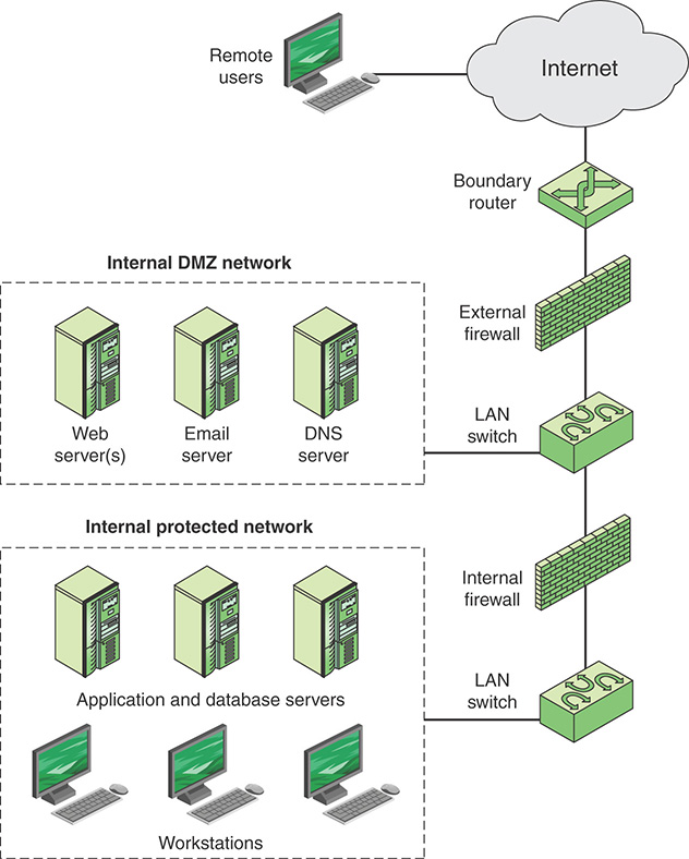
An external firewall provides a measure of access control and protection for the DMZ systems consistent with their need for external connectivity. An external firewall also provides a basic level of protection for the remainder of the enterprise network. In this type of configuration, internal firewalls serve three purposes:
An internal firewall adds more stringent filtering capability, compared to the external firewall, in order to protect enterprise servers and workstations from external attack.
An internal firewall provides two-way protection with respect to the DMZ. First, the internal firewall protects the remainder of the network from attacks launched from DMZ systems. Such attacks might originate from worms, rootkits, bots, or other malware lodged in a DMZ system. Second, an internal firewall protects the DMZ systems from attack from the internal protected network.
Multiple internal firewalls are used to protect portions of the internal network from each other. For example, firewalls are configured so that internal servers are protected from internal workstations and vice versa. A common practice is to place the DMZ on a different network interface on the external firewall from that used to access the internal networks.
The Modern IT Perimeter
Traditionally, the enterprise network perimeter was defined by the physical interface between network devices, such as routers, and external networks, such as the Internet and private WANs. For today’s enterprise, the perimeter is better defined by each node on the network and not the network itself. Key elements that break traditional network perimeter security are the following:
Wireless access points (APs): Wi-Fi APs that are either unknowingly or maliciously deployed inside the enterprise network enable mobile devices on the premises or near the premises to gain access to resources on the enterprise network.
Mobile devices: Mobile devices create a host of security issues, many of which are addressed in Chapter 7, “Physical Asset Management.” One issue specifically related to perimeter control is the ability of a mobile device to connect to the Internet via the cellular network. This makes it possible for a computer in the enterprise network to connect to the mobile device and through that device to the Internet, without going through perimeter firewalls.
An IBM red paper [BUEC09] suggests that the following elements should comprise network perimeter defense in a wireless environment:
The ability to globally enforce host-based security software deployed to the mobile systems known to access the enterprise network
Scanning for, discovering, and blocking unknown devices
Monitoring traffic patterns, communications, and transmitted data to discover how the enterprise network is being used and to uncover unwanted or threatening traffic from mobile devices
12.3 Virtual Private Networks and IP Security
This section introduces the concept of virtual private networks and examines IPsec, a common security mechanism used with VPNs.
Virtual Private Networks
A virtual private network (VPN) is a private network that is configured within a public network (a carrier’s network or the Internet) in order to take advantage of the economies of scale and management facilities of large networks. VPNs are widely used by enterprises to create wide area networks that span large geographic areas, to provide site-to-site connections to branch offices, and to allow mobile users to dial up their company LANs. From the point of view of the provider, the pubic network facility is shared by many customers, and the traffic of each customer is segregated from other traffic. Traffic designated as VPN traffic can only go from a VPN source to a destination in the same VPN. It is often the case that encryption and authentication facilities are provided for the VPN.
In today’s distributed computing environment, the VPN offers an attractive solution to network managers. In essence, a VPN consists of a set of computers that interconnect by means of a relatively insecure network and that make use of encryption and special protocols to provide security. At each corporate site, workstations, servers, and databases are linked by one or more LANs. The LANs are under the control of the network manager and are configured and tuned for cost-effective performance. The Internet or some other public network is used to interconnect sites, providing a cost savings over the use of a private network and offloading the WAN management task to the public network provider. That same public network provides an access path for telecommuters and other mobile employees to log on to corporate systems from remote sites.
But the manager faces a fundamental requirement: security. Use of a public network exposes corporate traffic to eavesdropping and provides an entry point for unauthorized users. To counter this problem, the manager can choose from a variety of encryption and authentication packages and products. Proprietary solutions raise a number of problems. First, how secure is the solution? If proprietary encryption or authentication schemes are used, there may be little reassurance in the technical literature about the level of security provided. Second is the question of compatibility. No manager wants to be limited in the choice of workstations, servers, routers, firewalls, and so on by a need for compatibility with the security facility. This is the motivation for the IPsec set of Internet standards.
IPsec
IPsec is a set of Internet standards that augment both versions of IP that are in current use (IPv4 and IPv6) with security features. The principal feature of IPsec is that it encrypts and/or authenticates all traffic at the IP level. Thus, all distributed applications—including remote logon, client/server, email, file transfer, web access, and so on—are secured.
IPsec provides three main facilities: an authentication-only function referred to as Authentication Header (AH), a combined authentication/encryption function called Encapsulating Security Payload (ESP), and a key exchange function. For VPNs, both authentication and encryption are generally desired because it is important both to (1) ensure that unauthorized users do not penetrate the virtual private network and (2) ensure that eavesdroppers on the Internet cannot read messages sent over the VPN. Because both features are generally desirable, most implementations are likely to use ESP rather than AH. The key exchange function allows for manual exchange of keys as well as an automated scheme.
Figure 12.6a shows a simplified packet format for an IPsec option known as tunnel mode, using ESP and a key exchange function. Figure 12.6b shows a typical IPsec usage scenario. An organization maintains local area networks (LANs) at dispersed locations. Insecure IP traffic is conducted on each LAN. For traffic offsite, through some sort of private or public WAN, IPsec protocols are used. These protocols operate in networking devices, such as a router or firewall, that connect each LAN to the outside world. The IPsec networking device typically encrypts and compresses all traffic going into the WAN and decrypts and decompresses traffic coming from the WAN; these operations are transparent to workstations and servers on the LAN. Secure transmission is also possible with individual users who dial in to the WAN. Such user workstations must implement the IPsec protocols to provide security.
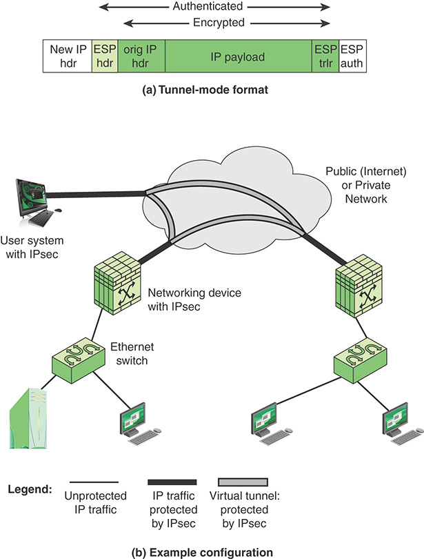
Tunnel mode provides protection to the entire IP packet. To achieve this, after the AH or ESP fields are added to the IP packet, the entire packet, including the security fields, is treated as the payload of new outer IP packet, with a new outer IP header. The entire original, inner, packet travels through a tunnel from one point of an IP network to another; no routers along the way are able to examine the inner IP header. Because the original packet is encapsulated, the new, larger packet can have totally different source and destination addresses, which increases the security. Tunnel mode is used when one or both ends of a security association (SA) are a security gateway, such as a firewall or router that implements IPsec. With tunnel mode, a number of hosts on networks behind firewalls can engage in secure communications without IPsec being implemented. The unprotected packets generated by such hosts are tunneled through external networks by tunnel mode SAs set up by the IPsec software in the firewall or secure router at the boundary of the local network.
Here is an example of how tunnel mode IPsec operates. Host A on a network generates an IP packet with the destination address of host B on another network. This packet is routed from the originating host to a firewall or secure router at the boundary of host A’s network. The firewall filters all outgoing packets to determine the need for IPsec processing. If this packet from host A to host B requires IPsec, the firewall performs IPsec processing and encapsulates the packet with an outer IP header. The source IP address of this outer IP packet is this firewall, and the destination address can be a firewall that forms the boundary to B’s local network. This packet is now routed to B’s firewall, with intermediate routers examining only the outer IP header. At B’s firewall, the outer IP header is stripped off, and the inner packet is delivered to B.
Firewall-Based VPNs
Figure 12.7 shows a typical scenario of IPsec usage. An organization maintains LANs at dispersed locations. Insecure IP traffic is conducted on each LAN. For traffic offsite, through some sort of private or public WAN, IPsec protocols are used. These protocols operate in networking devices, such as a router or firewall, that connect each LAN to the outside world. The IPsec networking device typically encrypts and compresses all traffic going into the WAN and decrypts and decompresses traffic coming from the WAN; authentication can also be provided. These operations are transparent to workstations and servers on the LAN. Secure transmission is also possible with individual users who dial in to the WAN. Such user workstations must implement the IPsec protocols to provide security. They must also implement high levels of host security, as they are directly connected to the wider Internet, which makes them an attractive target for attackers attempting to access the corporate network.
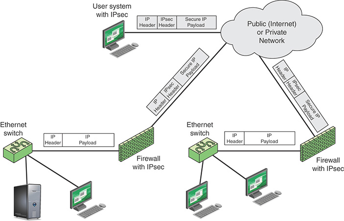
A logical means of implementing IPsec is in a firewall, as shown in Figure 12.8. If IPsec is implemented in a separate box behind (internal to) the firewall, then VPN traffic passing through the firewall in both directions is encrypted. In this case, the firewall is unable to perform its filtering function or other security functions, such as access control, logging, or scanning for viruses. IPsec can be implemented in the boundary router, outside the firewall. However, this device is likely to be less secure than the firewall and thus less desirable as an IPsec platform.
12.4 Security Considerations for Network Management
This section addresses the network management topics defined in the Information Security Forum’s (ISF’s) Standard of Good Practice for Information Security (SGP).
Network Device Configuration
The principal security objective related to network device configuration is to ensure that the configuration of network devices is accurate and does not compromise the security of the network.
The SGP recommends that policies and procedures for device configuration cover:
Security architecture principles
Standard security management practices
Device configuration
Restriction of access to network devices
Vulnerability and patch management
Changes to routing tables and settings in network devices
Regular review of network device configuration and setup
Configuring network devices is a complex undertaking. As vendors build more features into their routers, switches, firewalls, and application delivery controllers, the command-line syntax required to configure those devices becomes increasingly loaded with options and syntactic choices. Web-based graphical user interfaces (GUIs) are often available as an alternative to a command-line interface (CLI), but they can be slow to navigate. Web GUIs also have a way of obfuscating functions by hiding them in unlikely pages, making accessing them require an annoying series of clicks.
Analyses by numerous IT experts have time and again revealed that the most common cause of network outages is faulty configuration changes [BANK14]. Even minor errors in configuration changes to the devices in production carry the risk of causing network outage. Therefore, skilled network administrators spend a significant part of their time configuring devices. They may find it hard to concentrate on strategic network engineering and administration tasks.
Most configuration changes are repetitive, labor-intensive tasks, such as changing passwords and access control lists. A number of tools and vendor offerings can automate repeatable and complex tasks related to device configuration, reducing the chance of human error. A Zoho Corp. white paper [BALA15] outlines the following important characteristics of automated network device configuration management tools:
Multivendor device support: A tool should support all device types from all popular vendors.
Discovery capability for device addition: A network can have thousands of network devices, and it is labor intensive to add each device manually. A tool should allow for discovering the devices in the network and automatically adding them, in addition to other device addition options.
Communication protocols: A tool should support a wide range of protocols for establishing communication with the device and transferring configuration files.
Secure storage: A tool should store configuration data in encrypted form, protected against intrusion.
Inventory: A tool should provide an informative inventory of the devices being managed. It should provide various details, such as serial numbers, interface details, chassis details, port configurations, IP addresses, and hardware properties of the devices.
Configuration operations and schedules: A tool should provide simple, intuitive options in the GUI to carry out various configuration operations, such as retrieving, viewing, editing, and uploading configurations back to the device. It should include options to schedule the operations for automatic execution.
Configuration versioning: A tool should associate a version number with the configuration of each device, incremented with each change.
Baseline configuration: A tool should have a provision for labeling the trusted configuration version of each device as a baseline version to enable administrators to roll back a configuration to the baseline version in the event of a network outage.
Access control: A tool should include an attribute-based or role-based access control scheme, as described in Chapter 14, “Technical Security Management,” to provide security when multiple users have access to configuration tools.
Approval mechanism: The security policies of many enterprises require certain types of changes carried out by certain levels of users to be reserved for review and approval by top administrators prior to the deployment of the changes.
Physical Network Management
Physical network management is one aspect of physical security, a topic explored in some detail in Chapter 16, “Local Environment Management.” This section first lists some important aspects of physical network management and then introduces the TIA-492 infrastructure standard.
Network Aspects
Three aspects of physical network management are mentioned here:
Telecommunication cables: Telecommunication cables both within a site and providing external access to a site need to be physically protected. This includes using armored conduit, locking inspection/termination points, and avoiding routes through publicly accessible areas.
Network access points: It is important to store network access points in secure environments and make sure they are subject to physical security policies.
Network documentation: It is important to clearly document network configuration and functionality.
TIA-492
The Telecommunications Industry Association (TIA) standard TIA-492, Telecommunications Infrastructure Standard for Data Centers, specifies the minimum requirements for telecommunications infrastructure of data centers.
The standard specifies function areas and helps define equipment placement based on the standard hierarchical design for regular commercial spaces. This architecture anticipates growth and helps create an environment where applications and servers can be added and upgraded with minimal downtime. This standardized approach supports high availability and a uniform environment for implementing security measures. TIA-942 specifies that a data center should include functional areas, as shown in Figure 12.8.
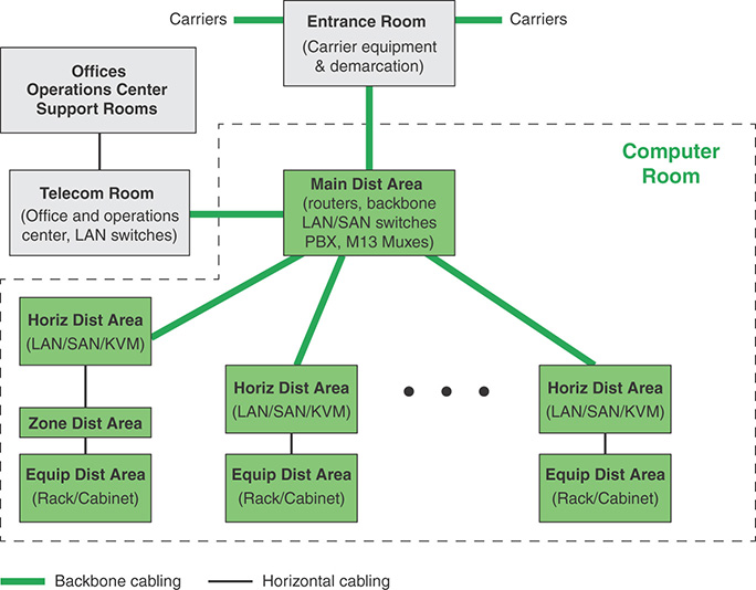
The functional areas are as follows:
Computer room: This is the portion of the data center that houses data processing equipment.
Entrance room: One or more entrance rooms house external network access provider equipment and provide the interface between the computer room equipment and the enterprise cabling systems. Physical separation of the entrance room from the computer room provides better security.
Main distribution area: This centrally located area houses the main cross-connect as well as core routers and switches for LAN and SAN (storage area network) infrastructures.
Horizontal distribution area (HDA): The HAD serves as the distribution point for horizontal cabling and houses cross-connects and active equipment for distributing cable to the equipment distribution area.
Equipment distribution area (EDA): The EDA is the location of equipment cabinets and racks, with horizontal cables terminating with patch panels.
Zone distribution area (ZDA): The ZDA is an optional interconnection point in the horizontal cabling between the HDA and EDA. The ZDA acts as a consolidation point for reconfiguration flexibility or for housing freestanding equipment such as mainframes.
An important part of TIA-942 that is especially relevant for computer security is the concept of tiered reliability. The standard defines four tiers, as shown in Table 12.4. For each of the four tiers, TIA-942 describes detailed architectural, security, electrical, mechanical, and telecommunications recommendations such that the higher the tier, the higher the availability.
TABLE 12.4 Data Center Tiers Defined in TIA-942
Tier |
System Design |
Availability/Annual Downtime |
|---|---|---|
1 |
|
99.671%/28.8 hours |
2 |
|
99.741%/22.0 hours |
3 |
|
99.982%/1.6 hours |
4 |
|
99.995%/0.4 hours |
Wireless Access
The security aspects of network management for wireless access have the objective of ensuring that only authorized individuals and computing devices gain wireless access to networks and minimizing the risk of wireless transmissions being monitored, intercepted or modified.
Dennis Kennedy’s article “Best Practices for Wireless Network Security” provides a useful list of risks associated with wireless access and mitigation techniques including the following:
Insufficient policies, training, and awareness: As with other areas, wireless security controls must include policies and user awareness training specifically for wireless access. These include procedures regarding uses of wireless devices and an understanding of relevant risks.
Access constraints: A wireless access point transmits, at regular intervals, a signal containing is Service Set Identifier (SSID). This unique SSID identifies the access point and is used to announce that the access point is active. Because SSIDs are transmitted unencrypted, an unauthorized use could exploit the SSID to attempt an attack or intrusion. Countermeasures include the following:
Enable device security features.
Change default settings, such as default SSIDs set by the manufacturer.
Use static IP addresses for wireless access points. This avoids the use of the Dynamic Host Configuration Protocol (DHCP), which automatically provides an IP address to anyone attempting to gain access to your wireless network. again Static IP addresses make unauthorized penetration more difficult.
Track employees who have WLANs at home or at a remote site. Require that wireless networks be placed behind the main routed interface so the institution can shut them off if necessary. If WLANs are being used at home, require specific security configurations, including encryption and VPN tunneling.
Rogue access points: Rogue access points are APs that users install without coordinating with IT. Access controls, encryption, and authentication procedures enable IT to maintain control.
Traffic analysis and eavesdropping: To counter this threat, it is necessary to use a strong user authentication technique and to encrypt all traffic.
Insufficient network performance: Poor performance is due to an imbalance in the use of access points, insufficient capacity planning, or a denial of service attack. The following steps can mitigate this risk.
Continually monitor network performance and investigate any anomalies immediately.
Segment the access point’s coverage areas to reduce the number of people using each access point.
Apply a traffic-shaping solution to allow administrators to proactively manage traffic rather than react to irregularities.
Hacker attacks: Hackers attempt to gain unauthorized access over wireless networks. Intrusion detection systems, anti-virus software, and firewalls are mitigation techniques.
Physical security deficiencies: This is in the domain of physical security. Subject Both the network devices and mobile devices to physical security policies and procedures.
Employ VPNs as an additional security control.
External Network Connections
The principal security objective with respect to external network connections is to prevent unauthorized external users from gaining access to information systems and networks. The SGP includes the following guidelines:
Restrict external network traffic to only specified parts of information systems and networks and defined entry points.
Verify the sources of external connections.
Limit access to devices that meet minimum security configuration requirements.
Restrict access to only specific enterprise applications.
Use firewalls to enforce security policies.
Use a VPN for devices.
Firewalls
The security management of firewalls requires a clearly defined firewall policy that is compatible with an overall security policy and a plan for the implementation and operation of the organization’s firewalls. The following subsections examine these two topics.
Firewall Policy
National Institute of Standards and Technology (NIST) SP 800-41, Guidelines on Firewalls and Firewall Policy, defines a firewall policy as a description of how an organization’s firewalls should handle inbound and outbound network traffic for specific IP addresses and address ranges, protocols, applications, and content types, based on the organization’s information security policies. SP 800-41 makes the following recommendations with respect to setting firewall policies:
Base an organization’s firewall policy on a comprehensive risk analysis.
Base firewall policies on blocking all inbound and outbound traffic, with exceptions made for desired traffic.
Take into account the source and destination of the traffic in addition to the content.
By default, block many types of IPv4 traffic, such as traffic with invalid or private addresses.
Have policies for handling incoming and outgoing IPv6 traffic.
Determine which applications in the organization send traffic into or out of its network and make firewall policies to block traffic for other applications.
Firewall Planning and Implementation
With respect to planning and implementation, SP 800-41 offers the following advice on the phases involved:
Plan: The first phase of the process involves identifying all requirements for an organization to consider when determining what firewall to implement to enforce the organization’s security policy.
Configure: The second phase involves all facets of configuring the firewall platform. This includes installing hardware and software as well as setting up rules for the system.
Test: The next phase involves implementing and testing a prototype of the designed solution in a lab or test environment. The primary goals of testing are to evaluate the functionality, performance, scalability, and security of the solution and to identify any issues—such as interoperability—with components.
Deploy: When testing is complete and all issues are resolved, the next phase focuses on deployment of the firewall into the enterprise.
Manage: After the firewall has been deployed, it is managed throughout its life cycle, including component maintenance and support for operational issues. This life cycle process is repeated when enhancements or significant changes need to be incorporated into the solution.
Remote Maintenance
Remote maintenance refers to maintenance activities conducted by individuals who are external to an information system’s security perimeter. Remote maintenance is a convenience to the enterprise; in some environments it is a necessity, as an Internet of Things (IoT) deployment or an industrial control system. The principal security objective in this area is to prevent unauthorized access to critical systems and networks through the misuse of remote maintenance facilities.
The U.S. Department of Homeland Security has compiled a list of requirements for remote maintenance of industrial control system [DHS11], but this list has general applicability to IT systems as well. The requirements for an organization are as follows:
Authorize, monitor, and control remotely executed maintenance and diagnostic activities.
Allow the use of remote maintenance and diagnostic tools only as consistent with organizational policy and documented in the security plan for the system.
Maintain records for remote maintenance and diagnostic activities.
Terminate all sessions and remote connections when remote maintenance is completed.
If password-based authentication is used to accomplish remote maintenance, change passwords following each remote maintenance session.
Audit remote maintenance and diagnostic sessions and ensure that designated organizational personnel review the maintenance records of the remote sessions.
Document the installation and use of remote maintenance and diagnostic links.
Require that remote maintenance or diagnostic services be performed from a system that implements a level of security at least as high as that implemented on the system being serviced or remove the component to be serviced from the system and, prior to remote maintenance or diagnostic services, sanitize the component (for example, clearing of set points, embedded network addresses and embedded security validation information). After the service is performed and the component is returned to the facility, the organization should check or reinstall the authorized firmware code as specified by the configuration management plan and reset all authorized embedded configuration settings. Do this before reconnecting the component to the system to remove potentially malicious software that was added via “new” firmware.
Require that remote maintenance sessions be protected by a strong authenticator tightly bound to the user.
Require that maintenance personnel notify the system administrator when remote maintenance is planned (that is, date/time).
Require that a designated organizational official with specific security/system knowledge approve the remote maintenance.
Implement cryptographic mechanisms to protect the integrity and confidentiality of remote maintenance and diagnostic communications.
Employ remote disconnect verification at the termination of remote maintenance and diagnostic sessions.
12.5 Electronic Communications
Often the focus of enterprise security is protecting stored information and server facilities, as well as client/server communication from the wide variety of threats on the landscape. It is important not to overlook security related to electronic communications that may not involve server or database access but that is between individuals. This section looks at four types of electronic communications that need to be protected.
It is useful to have a basic grasp of the Internet mail architecture, as defined in RFC 5598, Internet Mail Architecture. At its most fundamental level, the Internet mail architecture consists of a user world, in the form of message user agents (MUAs), and a transfer world, in the form of the Message Handling System (MHS), which is composed of message transfer agents (MTAs). The MHS accepts a message from one user and delivers it to one or more other users, creating a virtual MUA-to-MUA exchange environment. This architecture involves three types of interoperability. One is directly between users: Messages must be formatted by the MUA on behalf of the message author so that the message are displayed to the message recipient by the destination MUA. There are also interoperability requirements between the MUA and the MHS—first when a message is posted from an MUA to the MHS and later when it is delivered from the MHS to the destination MUA. Interoperability is required among the MTA components along the transfer path through the MHS.
Figure 12.9 illustrates the key components of the Internet mail architecture.
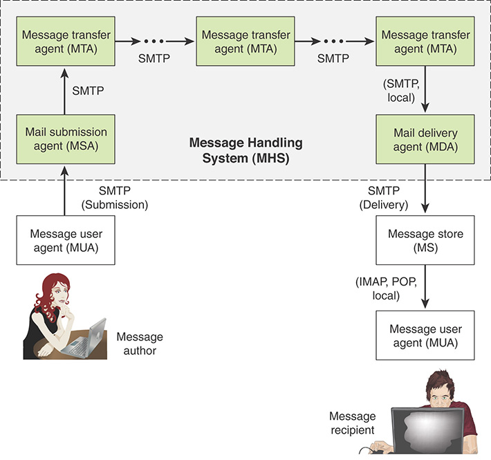
The key components include the following:
Message user agent (MUA): The MUA operates on behalf of user actors and user applications. It is their representative within the email service. Typically, this function is housed in the user’s computer and is referred to as a client email program or a local network email server. The author MUA formats a message and performs initial submission into the MHS via a MSA. The recipient MUA processes received mail for storage and/or display to the recipient user.
Mail submission agent (MSA): The MSA accepts the message submitted by an MUA and enforces the policies of the hosting domain and the requirements of Internet standards. This function is either located together with the MUA or as a separate functional model. In the latter case, Simple Mail Transfer Protocol (SMTP) is used between the MUA and the MSA.
Message transfer agent (MTA): The MTA relays mail for one application-level hop. It is like a packet switch or an IP router in that its job is to make routing assessments and to move the message closer to the recipients. Relaying is performed by a sequence of MTAs until the message reaches a destination MDA. An MTA also adds trace information to the message header. SMTP is used between MTAs and between an MTA and an MSA or MDA.
Mail delivery agent (MDA): The MDA is responsible for transferring the message from the MHS to the MS, using SMTP.
Message store (MS): The MUA employs a long-term MS, located on a remote server or on the same machine as the MUA. Typically, an MS retrieves messages from a remote MS using POP (Post Office Protocol) or IMAP (Internet Message Access Protocol).
Trustworthy Email Standards
For both organizations and individuals, email is pervasive and vulnerable to a wide range of security threats. In general terms, email security threats are classified as follows:
Authenticity-related threats: Can result in unauthorized access to an enterprise’s email system. Another threat in this category is deception, in which case the purported author isn’t the actual author.
Integrity-related threats: Can result in unauthorized modification of email content.
Confidentiality-related threats: Can result in unauthorized disclosure of sensitive information.
Availability-related threats: Can prevent end users from being able to send or receive email.
To assist in addressing these threat categories, the National Institute of Standards and Technology (NIST) issued SP 800-177, Trustworthy Email, which provides recommendations and guidelines for enhancing trust in email. The document is both a survey of available standardized protocols and a set of recommendations for using these protocols to counter security threats to email usage. The following protocols and standards are described in and recommended by SP 800-177:
STARTTLS: This SMTP security extension enables an SMTP client and server to negotiate the use of Transport Layer Security (TLS) to provide private, authenticated communication across the Internet.
S/MIME: S/MIME provides authentication, integrity, non-repudiation (via digital signatures) and confidentiality (via encryption) of the message body carried in SMTP messages.
DNS-based Authentication of Named Entities (DANE): DANE is designed to overcome problems in a certification authority (CA) system by providing an alternative channel for authenticating public keys based on DNSSEC (DNS Security Extensions), with the result that the same trust relationships used to certify IP addresses are used to certify servers operating on those addresses.
Sender Policy Framework (SPF): SPF enables a domain owner to specify the IP addresses of MTAs that are authorized to send mail on its behalf. SPF uses DNS to allow domain owners to create records that associate the domain name with a specific IP address range of authorized MTAs. It is a simple matter for receivers to check the SPF TXT record in DNS to confirm that the purported sender of a message is permitted to use that source address and reject mail that does not come from an authorized IP address.
DomainKeys Identified Mail (DKIM): DKIM enables an email actor (author or operator) to affix a domain name to the message reliably, using cryptographic techniques, so that filtering engines develop an accurate reputation for the domain. The MTA is able to sign selected headers and the body of a message. This validates the source domain of the mail and provides message body integrity.
Domain-based Message Authentication, Reporting and Conformance (DMARC): DMARC publishes a requirement for the author domain name to be authenticated by DKIM and/or SPF, for that domain’s owner to request recipient handling of non-authenticated mail using that domain, and a reporting mechanism from recipients back to domain owners. DMARC lets senders know the proportionate effectiveness of their SPF and DKIM policies and signals to receivers what action should be taken in various individual and bulk attack scenarios.
An examination of these standards is beyond the scope of this book. For a detailed discussion, see Stallings’s article “Comprehensive Internet Email Security” [STAL16]. A security manager must be aware of these standards and determine whether they should be required for email software products and services.
Another useful NIST document is SP 800-45, Guidelines on Electronic Mail Security, which complements SP 800-177. SP 800-45 recommends security practices for designing, implementing, and operating email systems on public and private networks. SP 800-177 focuses on the required Internet protocols and the use of digital signatures and encryption.
Acceptable Use Policy for Email
Many organizations provide email accounts for their employees that enable email to be sent and received within the organization as well as via the Internet. For such employees, it is recommended that an acceptable use policy be defined and agreed to by the employees. (See Section 4.3 for a general discussion of acceptable use policies.) As an example, an email acceptable use policy may include the following:
Acceptable behavior: Use of email by employees is permitted and encouraged where such use supports the goals and objectives of the business.
Unacceptable behavior: The following behavior by an employee is considered unacceptable:
Use of company communications systems to set up personal businesses or send chain letters
Forwarding of company confidential messages to external locations
Distributing, disseminating, or storing images, text, or materials that are considered indecent, pornographic, obscene, or illegal
Distributing, disseminating, or storing images, text, or materials that are considered discriminatory, offensive or abusive, in that the context is a personal attack, sexist or racist, or considered harassment
Accessing copyrighted information in a way that violates the copyright
Breaking into the company’s or another organization’s system or unauthorized use of a password/mailbox
Broadcasting unsolicited personal views on social, political, religious, or other non-business-related matters
Transmitting unsolicited commercial or advertising material
Undertaking deliberate activities that waste staff effort or networked resources
Introducing any form of computer virus or malware into the corporate network
Monitoring: The organization accepts that the use of email is a valuable business tool. However, misuse of this facility can have a negative impact on employee productivity and the reputation of the business. In addition, all of the company’s email resources are provided for business purposes. Therefore, the company maintains the right to examine any systems and inspect any data recorded in those systems. In order to ensure compliance with this policy, the company also reserves the right to use monitoring software in order to check up on the use and content of emails. Such monitoring is for legitimate purposes only and is undertaken in accordance with a procedure agreed with employees.
Sanctions: Where it is believed that an employee failed to comply with this policy, he or she faces the company’s disciplinary procedure. An employee who has breached the policy faces a disciplinary penalty ranging from a verbal warning to dismissal. The actual penalty applied depends on factors such as the seriousness of the breach and the employee’s disciplinary record.
Agreement: All company employees, contractors, or temporary staff who are granted the right to use the company’s email services are required to sign this agreement, confirming their understanding and acceptance of the policy.
Security Policy for Email
In addition to an acceptable use policy, an organization needs a security policy for email that specifies how email is to be handled, transmitted, and stored. ISO 27002, Code of Practice for Information Security Controls, includes the following considerations for protecting email:
Protecting messages from unauthorized access, modification, or denial of service commensurate with the classification scheme adopted by the organization
Ensuring correct addressing and transportation of the message
Ensuring reliability and availability of the service
Considering legal factors, such as requirements for electronic signatures
Obtaining approval prior to using external public services such as instant messaging, social networking, or file sharing
Specifying stronger levels of authentication to control access from publicly accessible networks
Instant Messaging
IM is a communications service in which short messages appear in pop-up screens as soon as they are received, thereby commanding the recipient’s immediate attention. IM uses a shared software client between or among two or more people using personal computers, smartphones, or other devices. The communication is done over a network, often the Internet, and can include advanced modes with live voice or video. File transfers are also sometimes allowed but are limited in size. Most IM services offer presence information that indicates whether a user is online and available to send and receive messages. These services also provide buddy lists, which are groups of people the user has selected for frequent access, as well as group-based chat services. Enterprise IM provides real-time message passing within private and public networks.
Although included in the online chat category of technologies, IM differs in that the communicating parties are selected from the buddy list, and users are typically alerted when someone on their list is online. In contrast, online chat allows communication in a multiuser environment among users who are usually anonymous.
IM also differs from text messaging. The primary difference is that text messaging is a cellular phone service that is typically limited to 160 characters, whereas instant messaging is usually a computer session with a longer message size. After a text message is transmitted, the session is essentially ended even though the recipient can respond and keep the back-and-forth going all day. When an instant messaging session is started, it remains connected until the session is ended by one of the parties.
Acceptable Use Policy for IM
A template for an instant messaging acceptable use policy developed by InfoTech includes the following rules that comprise the policy:
Supported IM Solution: [Company Name] has selected [name IM solution] as its sole provider of corporate IM services. Non-sanctioned IM services could affect network security, so the corporate firewall has been configured to block them. Free IM services commonly used within the consumer market are NOT approved or supported by the IT department.
Instant Messaging Usage & Security Policy https://www.infotech.com/research/instant-messaging-usage-and-security-policy
Acceptable Use: IM services are to be used for business communications and for the purpose of fulfilling job duties, in accordance with corporate goals and objectives. Use of IM communications in this manner between [Company Name] employees and project teams is permitted and encouraged. It is expected that all employees will communicate professionally with colleagues, keeping in mind that foul language and slang terms are not allowed. [Note: If IT allows external IM communications with business partners or clients, these can be referred to here. However, this should only be done with added security features provided by IM security vendors.]
Confidentiality: The transmission of sensitive corporate information through IM for business purposes is not permitted. Truly sensitive communications should be conducted through encrypted email or in-person meetings. Employees are prohibited from sending client lists, personal information, credit card information, trade secrets, and other proprietary information through the corporate IM service. In addition, it is prohibited to discuss legal advice or questions through IM with corporate lawyers, as this can violate the attorney-client privilege.
File Sharing: Though many IM services support the transmission of files, this feature has been blocked for IM at [Company Name]. [Note: Although InfoTech recommends the banning of file sharing altogether, if advanced network-based security controls are in place, this section can be modified to include that file sharing is permitted and that all files will be automatically scanned for viruses and monitored by IT.]
Personal Use: Limited personal use of corporate IM services to communicate internally with colleagues at [Company Name] regarding non-work-related matters is permitted during designated work breaks and lunch hours only. Even during allotted personal IM usage periods, employees may not use the service for unsolicited mass mailings, non-[Company Name] commercial activity, operation of a privately owned business, solicitation of funds, dissemination of political causes, or promotion of religious/personal beliefs to others.
Compliance: IM use at [Company Name] will comply with, all [Company Name] policies, all [Company Name] contracts and all applicable laws.
Privacy: IM conversations and messages created on the corporate IM service and transmitted through corporate systems will be considered the property of [Company Name]. [Company Name] reserves the right to monitor, inspect, copy, review, store, and audit IM usage and messages generated by or for the enterprise. [Company Name] is also obligated to disclose IM messages and conversations when ordered to do so by auditors, courts, and law enforcement, with or without the employee’s consent. Given these factors, employees do not have a reasonable expectation of privacy when using corporate IM services.
Security Policy for IM
IM is often poorly supervised, even though it introduces various risks to enterprise networks. Threats include IM-borne viruses, worms, spam over IM (SPIM), malware and phishing attacks, accidental or deliberate data leakage, inappropriate use, and regulatory noncompliance. A primary type of IM attack is to trick potential victims into installing a malicious program. IM-based attacks need some form of user interaction in order to launch, and attackers make use of social engineering to entice them to break security procedures or ignore common sense. These attacks usually exploit people’s innate curiosity or natural desire to help. They also try to appeal to vanity or authority and other triggers, such as greed, fear, anger, or moral duty.
Thus, if an enterprise is going to enable employees to use IM, a corporate IM security policy is essential, and it needs to be backed up by user awareness training and an acceptable use policy.
Two basic approaches enable an enterprise to maintain security over IM. Both approaches limit employees to the use of the enterprise-mandated IM facility and further limit the group of employees that can use IM. One approach is to host an enterprise IM server in-house. This enables the enterprise to enforce its IM policies through traffic analysis and reporting, message keyword searches, and message archiving. The enterprise can also implement end-to-end encryption and user authentication, as well as configure content and URL filters and allow the controlled use of many collaboration features, such as integrated live voice, video, and data.
The enterprise may also opt for a cloud service, which means there is no need to install additional hardware or software. All IM messages sent to or from the enterprise network are routed through the cloud service, where they are scanned for viruses, worms, and malicious URLs. Messages are also matched against enterprise content control and acceptable IM use policies: Messages that are malicious or suspicious or that violate policies are automatically blocked. Also, all messages are logged and can be sent to the enterprise’s existing archiving solution to satisfy legal discovery requirements and other relevant regulations. This type of service makes enterprise-grade control of IM accessible to organizations of all sizes.
Voice over IP (VoIP) Networks
VoIP has become increasingly prevalent in organizations of all sizes. In essence, VoIP involves the transmission of speech across IP-based network. VoIP works by encoding voice information into a digital format, which is carried across IP networks in discrete packets. VoIP has two main advantages over traditional telephony:
A VoIP system is usually cheaper to operate than an equivalent telephone system with a PBX and conventional telephone network service. There are several reasons for this. Whereas traditional telephone networks allocate dedicated circuits for voice communications using circuit switching, VoIP uses packet switching, allowing the sharing of transmission capacity. Further, packetized voice transmission fits well in the framework of the TCP/IP protocol suite, enabling the use of application- and transport-level protocols to support communications.
VoIP readily integrates with other services, such as combining web access with telephone features through a single PC or terminal.
VoIP Signaling
Before voice is transferred using VoIP, a call must be placed. In a traditional phone network, the caller enters the digits of the called number. The telephone number is processed by the provider’s signaling system to ring the called number. With VoIP, the calling user (program or individual) supplies the phone number of a URI (universal resource indicator, a form of URL), which then triggers a set of protocol interactions and results in the placement of the call.
The heart of the call placement process for VoIP is the Session Initiation Protocol (SIP), defined in RFC 3261, which is an application-level control protocol for setting up, modifying, and terminating real-time sessions between participants over an IP data network. SIP supports not only VoIP but also many multimedia applications. Associated with SIP is Session Description Protocol (SDP), defined in RFC 4566. SIP is used to invite one or more participants to a session, and the SDP-encoded body of a SIP message contains information about what media encodings (for example, voice, video) the parties can and will use. Once this information is exchanged and acknowledged, all participants are aware of the participants’ IP addresses, available transmission capacity, and media type. Then data transmission begins, using an appropriate transport protocol. Typically, Real-Time Transport Protocol (RTP) is used. Throughout the session, participants can make changes to session parameters, such as new media types or new parties to the session, using SIP messages.
An alternative to the use of SIP is ITU-T H.323. The H.323 protocol has been available for several years, and carriers made a significant investment to build out many large, H.323-based networks. SIP is growing in popularity due to its ability to easily combine voice and Internet-based services. SIP interoperability and coexistence with H.323 is very important to maximize the return on current investments and to support new deployments that might use SIP as an alternative packet telephony signaling protocol.
VoIP Processing
In a VoIP system, when a called party responds, a logical connection is established between the two parties (or more parties, for a conference call), and voice data can be exchanged in both directions. Figure 12.10 illustrates the basic flow of voice data in one direction in a VoIP system. On the sending side, the analog voice signal is first converted into a digital bit stream and then segmented into packets. The packetization is performed, typically, by RTP. This protocol includes mechanisms for labeling the packets so that they can be reassembled in the proper order at the receiving end, plus a buffering function to smooth out reception and deliver the voice data in a continuous flow. The RTP packets are then transmitted across the Internet or a private intranet using User Datagram Protocol (UDP) and IP.
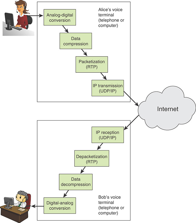
At the receiving end, the process is reversed. The packet payloads are reassembled by RTP and put into the proper order. The data are then decompressed, and the digitized voice is processed by a digital-to-analog converter to produce analog signals for the receiver’s telephone or headset speaker.
VoIP Context
Ultimately, VoIP using IP-based networks may replace the public circuit-switched networks in use today. But for the foreseeable future, VoIP must coexist with the existing telephony infrastructure. Figure 12.11 shows some of the key elements involved in the coexistence of these older and newer technologies.
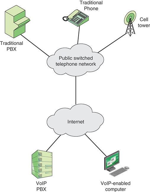
The deployment of the VoIP infrastructure is accompanied by a variety of end-user products, including the following:
Traditional telephone handset: These corded or cordless units function much like traditional telephones but are VoIP capable. They typically have many additional features, making use of a screen, and providing capabilities similar to those of smartphones.
Conferencing units: These provide the same basic service as conventional conference calling phone systems and also allow users to coordinate other data communications services, such as text, graphics, video, and whiteboarding.
Mobile units: Smartphones and other cellphones with VoIP capability can tie directly into a VoIP network without needing to go through any kind of gateway system.
Softphone: The term softphone refers to software operating on a PC that implements VoIP. Typically, the PC is configured with a headset or with a telephone that makes use of a USB connection to the PC.
A wide variety of infrastructure equipment has been developed to support VoIP. There are two noteworthy types:
IP PBX: The IP PBX is designed to support digital and analog phones and connect to IP-based networks using VoIP, as well as provide a connection to the public switched telephone network using traditional technology, if needed.
Media gateway: The media gateway connects different physical networks in order to provide end-to-end connectivity. An important type of media gateway connects a VoIP network to a circuit-switched telephone network, providing the necessary conversion and signaling.
The VoIP environment continues to evolve, and a large number of products are being developed for providers, businesses, and residential/personal users.
VoIP Threats
As VoIP becomes mainstream, a number of security issues must be understood and addressed. Key areas of concern are as follows:
VoIP traffic travels through the Internet. It is possible that a hacker could use a packet sniffer to listen to unencrypted VoIP traffic. The solution lies in setting up a VPN between the endpoints, but doing so also introduces additional complications.
Many older firewalls may not recognize VoIP packets. In addition, some intrusion detection systems may try to inspect voice packets, thereby introducing delay and jitter. Bypassing the traffic inspection rules in the firewall may create additional vulnerability.
Many older VoIP phones may require security patches for their software. Such patches are seldom applied as many administrators are not even aware that phone software needs to be patched. Some VoIP phones are set up to apply patches directly without even asking for authentication. Such phones can be very vulnerable to hackers.
Phones also inherit the security flaws of the operating systems they use.
Systems used out of the box may have default passwords and open ports that need to be managed and secured. In many cases, this is ignored.
DoS attacks can be launched against a VoIP phone system, just as they can be launched against other computer applications.
The following are some specific threats to the use of VoIP:
Spam over Internet telephone (SPIT): Unsolicited bulk messages may be broadcast over VoIP to phones connected to the Internet. Although marketers already use voicemail for commercial messages, IP telephony makes a more effective channel because the sender can send messages in bulk instead of dialing each number separately.
Eavesdropping: Interception of control packets enables an adversary to listen in on an unsecured VoIP call.
Theft of service: This type of attack involves capturing access codes, allowing the adversary to get into the VoIP provider network and then use the facility.
Man-in-the middle attack: This type of attack involves an adversary inserting as a relay point between two ends of a VoIP call. In addition to eavesdropping, the adversary could divert a call to a third party or generate simulated voice content to create misleading impressions or cause operational errors.
VoIP Security Measures
A number of security measures can be taken to protect VoIP traffic, including the following:
Encryption: It is a good practice to encrypt all voice connections.
VPNs: VPNs create segregated broadcast domains within the IP network infrastructure. By creating VPNs for voice, organizations provide an additional layer of protection that can potentially insulate voice communications from DoS attacks and other risks.
Port administration: SIP applications tend to open multiple ports on network devices, creating additional exposure to hackers. Therefore, IT staff need to implement firewalls and other security administration tools that discover and close unnecessarily opened ports—and rigorously authenticate devices attempting to use those ports.
Real-time antivirus scanner: An organization should scan the VoIP server continuously.
Application-layer firewall: This protects assets associated with the VoIP server, such as a database devoted to logging calls or even recording the calls.
Device authentication: Any user device that attempts to use the VoIP service should be authenticated.
User authentication: Individual users should be authenticated to limit specific users or groups of users to specific VoIP services.
Telephony and Conferencing
The security objective with respect to telephony and conferencing is to prevent and detect unauthorized use or misuse of telephony and conferencing facilities. This is achieved with a combination of physical and logical controls. The SGP recommends that there should be policies that cover the following:
Use of the organization’s telephones
Moves and changes of telephone users
Registration and authentication of users with access to voicemail
Protection of voicemail systems against unauthorized access (for example, by use of password protection)
The use and setup of web-based conferencing facilities (including teleconferencing, videoconferencing, and online web-based collaboration)
12.6 Networks and Communications Best Practices
The SGP breaks down best practices in the networks and communication category into 2 areas and 10 topics and provides detailed checklists for each topic. The areas and topics are as follows:
Network management: The objectives of this area are to (1) design physical, wireless, and voice networks to be reliable and resilient; prevent unauthorized access; encrypt connections; and detect suspicious traffic and (2) configure network devices (including routers, firewalls, and wireless access points) to function as required and to prevent unauthorized or incorrect updates.
Network device configuration: Lists the key practices to ensure that network devices (including routers, switches, and firewalls) are configured to function as required and to prevent unauthorized or incorrect updates.
Physical network management: Addresses issues related to the physical protection of network devices and communications links.
Wireless access: Provides a policy checklist for managing wireless access.
External network connections: Provides a policy checklist for managing and protecting external network connections.
Firewalls: Details the types of firewalls to be used and provides guidelines for firewall security policy.
Remote maintenance: Lists measures to protect remote maintenance facilities from misuse.
Electronic communications: The objectives of this area are to protect electronic communication systems by setting policy for their use; configuring security settings; and hardening the supporting technical infrastructure. Four topics are covered: email, instant messaging, VoIP, and telephone/conferencing. For each of these topics, the SGP provides checklists of policies and procedures to secure against misuse.
12.7 Key Terms and Review Questions
Key Terms
After completing this chapter, you should be able to define the following terms.
message submission agent (MSA)
stateful inspection firewall
Review Questions
Answers to the Review Questions can be found online in Appendix C, “Answers to Review Questions.” Go to informit.com/title/9780134772806.
1. According to ISO 7498-4, what are the key functions of network management?
2. What are some of the key tasks performed by a network management entity?
3. How is a distributed network management system organized?
4. Explain the network management architecture defined by Cisco.
5. Name all the techniques that firewalls use to control access to a site and enforce the site’s security policy.
6. What are some common types of firewalls?
7. What are some of the weaknesses of packet filters?
8. What are some of the important characteristics of automated network device configuration management tools?
9. According to TIA-942, which functional areas are included in a data center?
10. What are some of the key risks associated with wireless access?
11. According to SP 800-41, how are firewall planning and implementation phases defined?
12. In general, how can you classify email security threats?
13. According to ISO 27002, how can an organization protect email?
14. Describe two types of infrastructure equipment that support VoIP.
15. What are some of the principal threats to VoIP usage?
16. How does the Standards Customer Council define the key components of a cloud service agreement (CSA)?
12.8 References
BALA15: Balasubramanian, V., Conquering the Operational Challenges of Network Change & Configuration Management Through Automation. Zoho Corp. white paper, 2015. https://www.manageengine.com/network-configuration-manager/network-configuration-management-overview.html
BANK14: Banks, E., “Automating Network Device Configuration.” Network World, July 2014.
BELL94: Bellovin, S., and Cheswick, W. “Network Firewalls.” IEEE Communications Magazine, September 1994.
BEUC09: Buecker, A., Andreas, P., & Paisley, S., Understanding IT Perimeter Security. IBM red paper REDP-4397-00, November 2009.
CISC07: Cisco Systems, Cisco Advanced Services Network Management Systems Architectural Leading Practice. White Paper C07-400447-00, September 2007. https://www.cisco.com/en/US/technologies/tk869/tk769/technologies_white_paper0900aecd806bfb4c.pdf
DHS11: U.S. Department of Homeland Security. Catalog of Control Systems Security: Recommendations for Standards Developers. Industrial Control Systems Cyber Emergency Response Team (ICS-CERT) Report, April 2011.
KENN03: Kennedy, S., “Best Practices for Wireless Network Security.” ComputerWorld, November 23, 2003.
STAL16: Stallings, W., “Comprehensive Internet Email Security.” Internet Protocol Journal, November 2016. Available at http://williamstallings.com/Papers/