Plans and Elevations
Two major documents form the basis of studio production planning – the staging plan/floor plan and scenic elevations.
The studio plan
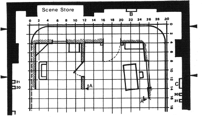
The empty studio plan is a standard scale drawing of the entire studio–typically to a metric scale of 1:50; i.e. 2 cm = 1 m. (Formerly ¼ in to 1 ft scale was used.) Printed on tracing paper, it may show such features as:
• The location of storage areas, and service areas (makeup, changing rooms, etc.).
• All entrances/exits, scenic loading bay, stairways, access points, etc.
• The staging area within which scenery can be erected,
• The 1 m/3 ft wide safety lane (fire lane) around the studio.
• The positions of various general supplies; e.g. gas, water, power.
• The positions of all outlets/technical supplies for camera, sound, lighting.
• The location of overhead lighting support systems (battens, rails, etc.).
• The position of the cyclorama support rails.
• Data on heights, weight-carrying capacities, sizes, etc.
How the studion plan is used
From the studio plan, major reference documents are derived;
• The staging plan (floor plan, ground plan, setting plan). The set designer/scenic designer draws scale outlines of settings (‘sets’) on the studio plan. In a complex production, sets drawn on individual tracing overlays are readjusted for optimum camera, lighting and sound access.
• Furniture/props plan. This is a detailed plan of a setting, showing where furniture, decorations, drapes, are to be placed.
• The camera plan (production plan). The director draws on a copy of the staging plan, the numbered positions of all cameras and sound booms, perhaps with indications of camera cable routes. This camera plan is used at the production planning meeting when the director explains the envisioned camera treatment.
The camera plan is also used by the camera crew and sound crew, before and during rehearsal, to guide them in positioning their equipment
• The lighting plot may be drawn on a copy of the camera plan, or on a separate tracing overlay. Lighting fitting symbols are drawn in their required ‘rigged positions’, with details of power supply channels, accessories, color media, etc.
Elevations
Elevations show side-on views of ail scenery to the same scale as the staging plan. They give details of all vertical structures’ construction and finish (walls, staircases, etc.). Used primarily by construction workshops, and the crew setting up the scenery, they help all. members of the team to imagine what the actual scenery will look like when erected.

The staging plan
Scale outlines of settings are drawn on the studio plan.

Elevations
These show details of all vertical structures. The sizes, style, finish of walls, together with details of special features, are included (c, d, f, j).
