
7
Geothermal energy
Tubagus Ahmad Fauzi Soelaiman Mechanical Engineering Department, Faculty of Mechanical and Aerospace Engineering, Thermodynamics Laboratory, Engineering Centre for Industry, Institut Teknologi Bandung, Bandung, Indonesia
Abstract
This chapter describes geothermal energy from its definition to use as a form of energy. Direct as well as indirect uses of the geothermal energy are covered in detail to give an overall view. Different types of geothermal power plants are described in detail. As a high intensity renewable energy that is available continuously, but cannot be exported, geothermal energy must be considered as an energy source in areas where they are available.
Keywords
geothermal energy
direct use
indirect use
geothermal power plant
7.1. Introduction
The term “geothermal energy” is derived from the Greek words “ge,” which means earth, “therme,” which means heat, and “energos,” which means active or working [1]. Therefore, geothermal energy can be considered as the active heat energy from within the earth.
Geothermal energy is considered renewable if its demand does not surpass its supply. Among other renewable energies (solar, wind, bio, hydro, and ocean/marine), geothermal is desirable since it has a high energy density, unlike wind energy, for example; and it is available continuously unlike solar energy, for example. But unlike fossil fuels such as oil, gas, and coal, geothermal energy cannot be exported or transported over long distances. It must be used in situ to use its heat directly or to produce electricity.
Geothermal energy is mostly available in areas close to the Ring Of Fire, where Earth’s tectonic plates meet. Therefore, the map in Figure 7.1 can be used to determine with relatively high probability the locations of geothermal energy sources. These locations, while benefiting from the availability of geothermal energy, must also endure the risk of volcanic eruptions.

Geologically, geothermal energy may manifest itself in forms of: volcanoes, lava flows, geysers (hot springs that spew water into the air intermittently), fumaroles (small holes that release dry steam or wet steam), hot/warm springs (springs that release hot/warm water), hot/warm pools (pools with a higher temperature than the surroundings, which indicate that a geothermal heat source is present under the surface), hot lakes (hot pools with larger surface area), mud pools (pools of hot mud, usually with CO2 bubbling from the ground), steaming grounds (grounds that release steam), warm grounds (grounds with higher temperature than the surroundings), and silica sinters (silvery silica condensation that create silica sinter terraces or sinter platforms) [3,4]. These manifestations reveal that geothermal energy is available and may be tapped from below the ground.
Figure 7.2 shows a typical geothermal field that can be found on Earth. From the center of the Earth, the nearest magma to the surface is shown in Figure 7.2. It solidifies into igneous rock or impermeable rock, also known as volcanic rock, if found at the surface. The magma heats the igneous rock by conduction, which in turn heats ground water by convection in a water reservoir and permeable rock. This reservoir is capped by an impermeable cap rock on top. The rock may have fissures to vent the heated reservoir. The vent may be formed naturally as geysers, fumaroles, or hot springs; or it may be purposely tapped by using a production well for a geothermal power plant. The cooled fluid can be returned to earth using a reinjection well.

Figure 7.2 A typical geothermal field.
Steam originating from the magma itself is called magmatic steam, while that from ground water heated by the magma is called meteoritic steam [4].
The geothermal source described earlier produces steam. But not all sources produce steam. Some produce warm water, while others produce no water at all, just hot dry rocks (HDRs). According to the energy sources, geothermal sources are usually divided into hydrothermal, geopressured, and petrothermal [4].
Hydrothermal systems are those with water heated by the hot rock. If water is heated to create mostly vapor, then it is called vapor-dominated system. But if a majority of the water is still liquid, then it is called a liquid-dominated system [4].
Geopressured systems are those having water trapped in much deeper underground reservoirs, about 2000–9000 m, with low temperature (about 160°C) and high pressure (about >1000 bar). It has a high salinity of about 4–10% and is highly saturated with natural gas, mostly methane that can be recovered for electric generation. This methane can be combusted to produce electricity, while the heat of the water can also be used to produce electricity [4].
Petrothermal systems are those without naturally occurring water. The heat source is in the form of an HDR. Heat can be extracted by pumping water into the cracked HDR. The steam produced can then be used to produce electricity [4].
7.2. Geothermal energy uses and types
The possible uses of geothermal energy can be found, but are not limited to, as shown in a Lindal diagram. The diagram has been modified from the original version in 1973 [5] into several forms such as the one shown in Figure 7.3 [6]. From the diagram, it can be shown that low temperature of a heat source or a reservoir can be used for domestic hot water, greenhouses, copper processing, soil warming, fish farming, etc. In the meantime, high temperature reservoirs can be used to produce electricity by using steam turbines and generators in power plants. This electricity can be easily transmitted using transmission lines to consumers.

When geothermal energy is used as heat for bathing, house heating, cultivating plantations, etc., it is known as the direct use of geothermal energy. But when geothermal energy is converted into electricity through a thermodynamic process/cycle, then it is known as the indirect use of geothermal energy.
7.2.1. Direct use of geothermal energy
Direct use of geothermal energy by making use of the heat directly, is the oldest and most common use of geothermal energy. People have been bathing for hundreds of years in naturally occurring ponds or lakes that are heated by geothermal sources. By directing the hot water/steam/brine, geothermal energy has also been used directly for space heating, district heating, snow melting, road deicing, agricultural heating/drying, etc., especially in cold countries. Several examples of direct use of geothermal energy are presented in Section 7.2.1.1.
7.2.1.1. Space or object heating
Space or object heating by using geothermal energy is the most obvious use. By directing the steam, water, or brine from a geothermal energy source to a space or an object, the temperature of the space or object can be increased and/or maintained. The heat can be directly obtained from geothermal fluids, or these geothermal fluids can heat another fluid such as water, or air to heat the space or object. When using additional fluids, the system may be more complex but the temperature can be usually controlled more precisely and easily. Furthermore, by using additional fluid, some parts of the system can avoid the undesirable properties of geothermal fluid, such as its corrosiveness.
An example of the use of geothermal energy in a district heating system in Reykjavik, Iceland, is shown in Figure 7.4. Three production wells are used to supply the houses with 80°C fluid. The cooled fluid leaves at 35°C to the drains.

Figure 7.4 An example of direct use of geothermal energy in a district heating system in Reykjavik, Iceland. Adapted from Ref. [6].
To extract heat from the ground, a piping system can be utilized in several loop configurations as shown in Figure 7.5 [7]. If ground space is available, a horizontal loop configuration can be used by digging low cost trenches in the ground deep enough to obtain a constant temperature. In case ground space is limited, the piping can be in a vertical loop configuration by drilling wells into the ground. If a pond is available nearby, the piping loops can be submerged below the surface of the pond, reducing the cost of digging. Lastly, if underground water is available, the warm water can be pumped up to heat up the system and then the cooled water can be released into a pond.

Figure 7.5 Several configurations of the piping system for geothermal warming. Adapted from Ref. [7].
In agriculture, it has been known that certain plants grow rapidly in certain surrounding temperatures. Examples for lettuce, tomato, and cucumber are shown in Figure 7.6 [6]. Of course, other variables are also important such as the type of soil, amount of light, CO2 concentration, humidity of air and soil, and air movement. By adjusting these variables in a controlled enclosure, one can grow agricultural products optimally in any season or in any weather condition, giving better food security.

Figure 7.6 Effect of temperature on the growth of lettuce, tomato, and cucumber. Adapted from Ref. [6].
Geothermal heat can be used to heat these and other agricultural products in greenhouses, at the optimum temperature for best growth. Several possible piping and ducting systems that can be used in greenhouses are shown in Figure 7.7 for natural as well as forced air movements. Additional examples of direct uses of geothermal energy for agricultural products, such as coconut drying, coffee drying, cocoa drying, palm sugar production, and mushroom production, can also be found in Soelaiman [8].

Figure 7.7 Examples of using piping/ducting systems for geothermal heating in greenhouses.
Heating installations with natural air movement (natural convection): (a) aerial pipe heating; (b) bench heating; (c) low-position heating pipes for aerial heating; and (d) soil heating. Heating installations with forced air movement (forced convection): (e) lateral position; (f) aerial fan; (g) high-position ducts; and (h) low-position ducts. Adapted from Ref. [6].
Heating installations with natural air movement (natural convection): (a) aerial pipe heating; (b) bench heating; (c) low-position heating pipes for aerial heating; and (d) soil heating. Heating installations with forced air movement (forced convection): (e) lateral position; (f) aerial fan; (g) high-position ducts; and (h) low-position ducts. Adapted from Ref. [6].
For farm animals and aquatic species, temperature of the surroundings can also affect the growth rate. Figure 7.8 shows the percentage growth rates of several farm animals and aquatic species. The aquatic species that are typically raised in controlled temperatures are carp, catfish, bass, tilapia, mullet, eel, salmon, sturgeon, shrimp, lobster, crayfish, crab, oyster, clam, scallop, mussel, abalone, etc. [6]. Geothermal heat can of course be used to obtain the optimum growth temperature of the farm or pond with similar installations as shown in Figure 7.5.

7.2.1.2. Geothermal heat pump
A heat pump is a device that takes heat from a cold source and releases the heat into a hot sink. The working operation of a heat pump is in the reverse order of refrigeration cycle. In fact, an air conditioning system can be used as a heat pump, just by placing the condenser in the cold source and the evaporator in a hot sink. But rather than physically moving the units, a special valve can be used to reverse the direction of a refrigeration cycle into a heat pump cycle. An example of a heat pump to warm domestic water and a space with the possible use of a geothermal heat source can be seen in Figure 7.9. The heat pump can be used to heat a space with less energy by using reduced electrical energy to run the refrigerant compressor rather than directly heating the space by electricity.

Figure 7.9 Heat pump heating water and air for domestic use.
A heat pump can be used to extract heat from the outside of a house into the inside. But during the winter season where the temperature of the outside air is very low, the heat pump has to work harder due to the large temperature difference. In the meantime, the temperature of the soil a few meters below the ground usually remains constant at about 13°C (55°F). Therefore, rather than taking heat from the cold outside air, the heat pump can take the heat from the warmer ground, which will reduce the amount of power needed to heat the house. A schematic diagram of the use of a heat pump for geothermal heating is shown in Figure 7.10 [9].

7.2.1.3. Geothermal cooling
In the summer season where the temperature of air is high (25–40°C) and the temperature of the subsoil is low (about 13°C), water or air can be injected or blown into the ground, cooled, and then resurface into a space or an object to be cooled by a heat exchanger. The loop installation may be similar to the ones in Figure 7.5, but for cooling. This is a type of ground cooling that takes advantage of the cooler subsoil compared to the outside air temperature.
Geothermal energy can also be used as the heat source of an absorption refrigeration cycle. An example of the absorption cycle is shown in Figure 7.11 where ammonia(NH3) is used as the refrigerant and water (H2O) as the absorber. Alternatively, water (H2O) can be used as the refrigerant and lithium bromide (LiBr) as the absorber. In Figure 7.11, geothermal heat is used to heat the generator while the evaporator is cooling the space or the object to be cooled. Compared to a vapor refrigeration, which uses a compressor, absorption refrigeration is less costly to operate since it uses a pump. A comprehensive explanation of how an absorption refrigeration system works is beyond the scope of this book. Please refer thermodynamics or refrigeration system books for further information.
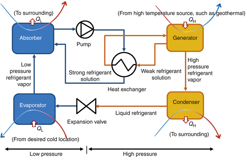
Figure 7.11 Absorption refrigeration cycle that can use geothermal energy as a heat source.
7.2.1.4. Calculations for direct use of geothermal energy
The calculations for direct use of geothermal energy usually involves the sizing and material selection of heat exchangers, ducting systems, pipes, pumps, and fans. This is also beyond the scope of this book. Please refer heat transfer and equipment sizing books for the proper calculation methods. The log mean temperature difference method is usually used to size the equipment, given the states of the working fluids. Alternatively, the number of transfer units-ɛ method is usually used to calculate whether the size of equipment can transfer the amount of heat as required.
7.2.2. Indirect use of geothermal energy
As stated earlier, the indirect use of geothermal energy usually refers to electricity generation by using heat from the geothermal source. Basically, this geothermal power plant is similar to steam power plants, but it uses earth as the natural boiler. The first engine used at Larderello, Italy in 1904 to produce electricity from geothermal steam was invented by Prince Piero Ginori Conti [6]. Section 7.2.2.1 analyzes the geothermal power plant from its simplest form to more complex systems.
7.2.2.1. The simplest geothermal power plant
In its simplest form, the steam extracted from the geothermal well can be directly expanded in a turbine, which turns a generator to produce electricity. The process flow diagram (PFD) and the process diagram on the T–s diagram of this geothermal power plant are shown in Figure 7.12. Drawing the process on h–s and P–h diagrams should also be exercised.
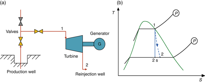
Figure 7.12 The simplest form of a geothermal power plant.
(a) Schematic of the PFD. (b) T–s process diagram.
(a) Schematic of the PFD. (b) T–s process diagram.
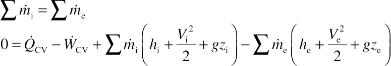
To analyze the process that occurs on the working fluid, mass and energy conservation laws on a control volume (CV) are needed, which can be found in many thermodynamic books, such as by Moran and Shapiro [10]. They can be written as:

In a steady-state condition, the fluid states do not depend on time, therefore: dmCV/dt = 0 and dECV/dt = 0. Then:
Applying these equations into a turbine and by assuming that there is no mass leakage on the turbine, the mass conservation law can be written as:
Assuming the turbine is adiabatic (no heat loss), and the changes of kinetic and potential energies are negligible, then the energy conservation law on the turbine can be written as:
If the isentropic efficiency (ηi) of the turbine is known from a test, then the real work produced from the turbine can be written as:
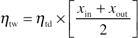
The isentropic efficiency of a dry turbine (ηtd) is usually taken as 85%. But in the case of a geothermal power plant, it is almost certain that the condition of the steam exiting the turbine is at a two-phase region. According to Bauman in DiPippo [11], the Baumann rule states that 1% average moisture causes approximately 1% drop in turbine efficiency. Another way to approximate the efficiency of a wet turbine (ηtw) is to use the following equation [11]:
This simplest form of geothermal power plant is seldom utilized since the low quality of steam and presence of impurities within the steam may not be suitable for direct feeding into a turbine. In practice, a separator usually has to be used to dry the steam from water droplets and remove the impurities from within the steam near the well or in a header that receives steam from several wells. Assuming that there is no mass leakage in the separator (brine and solids released during blowdown under the separator are negligible), the separator is adiabatic due to the good insulator, and change of kinetic and potential energies can be neglected, then the process in the separator can be considered at constant enthalpy (isenthalpic). Therefore, the mass and energy conservation laws can be written as:

If the separator continuously releases liquid or brine, then the separator also separates the liquid from the dry steam at the pressure of the separator. Therefore, the process in the separator will consist of an isenthalpic pressure drop and a constant pressure (isobaric) steam and liquid separation. The PFD and process diagram of the simplest geothermal power plant with this type of separator can be seen in Figure 7.13.

Figure 7.13 Schematic and process diagrams of the simplest geothermal power plant with a separator.
Example 7.1
Solution
Following the isenthalpic, isobaric, and isentropic lines, the h–s and P–h diagrams of the simplest geothermal power plant with a separator can be seen in Figure 7.14.

Figure 7.14 The h–s and P–h diagrams of the simplest geothermal power plant with a separator.
Example 7.2
After the valves of the production well, steam enters a separator at flow rate ( ) = 400 t/h, P = 12 bar (absolute), and x = 70%. If the drop of pressure in the separator is 2 bar, and the isentropic efficiency of the dry turbine is 85%, calculate the power produced by the turbine if the steam is expanded into 1 atm and 0.6 atm. Discuss the results.
Solution
The schematic and T–−s diagram of the cycle would be similar to those in Figure 7.13.
Mass flow rate () is 400 t/h or 400 t/h × (1000 kg/t) × (1 h/3600 s) = 111.11 kg/s.
At P = 12 bar and x = 70%, h1 can be calculated as h1 = hf + x (hg – hf). The thermodynamics properties can be found in any steam table or steam calculator. For this example, the steam calculator can be found at http://www.peacesoftware.de/einigewerte/calc_dampf.php5. Entering P = 12 bar (absolute) on the menu “Calculation of thermodynamic properties of saturated steam,” and by pressing enter or clicking on the menu “Compute,” the properties of thermodynamic properties are calculated.
Calculating h1 = hf + x × (hg – hf) = 798.49 + (0.70) × (2787.77 − 798.49)) = 2188.186 kJ/kg.
Assuming the drop of pressure occurs at isenthalpic pressure, then h2 = h1 = 2188.186 kJ/kg.
Calculating the quality at 2: x2 = (h2 – hf)/(hg – hf) = (21.88.186 – 792.68)/(2777.12 – 762.68) = 0.7032, or 70.32%. There is a slight increase of quality compared to point 1.
Entering 10 bar at “Calculation of thermodynamic properties of saturated steam” of the online steam calculator, the properties in saturation lines can be found. Calculate s2 at 10 bar: s2 = sf + x × (sg – sf) = 2.1384 + 0.7032 × (6.5849 − 2.1384) = 5.2651788 kJ/kgK.
Point 3s has the same entropy value as point 2, since the ideal process is considered isentropic. Therefore, s3s = s2 = 5.2651788 kJ/kgK. Then steam quality of this point can be calculated as: x3s = (s3s – sf)/(sg – sf) = (5.2651788 – 1.067)/(7.35438 – 1.3067) = 0.6545(65.45%).
Searching the saturated thermodynamics properties at the exit of the turbine at 1 atm (1.01325 bar), then by entering 1.01325 as the pressure, and using the obtained saturated properties, we can calculate h3s = hf + x(hg – hf) = 418.9907 + 0.6545(2675.53 – 418.99) = 1895.896 kJ/kg.
Therefore, assuming the isentropic efficiency of the turbine as 85%, then the power of the turbine is:  = × (ηiT)(h2 – h3s) = 111.11 kg/s × (0.85)(2188.186 – 1895.896) = 27604.85 kJ/kg s = 27 MW.
If somehow the outlet of the turbine can be vacuumed into 0.6 atm (0.61 bar), then, using the properties at 0.61 bar:
Note that by reducing the outlet of the pressure from 1 atm to 0.6 atm, there will be an increase of the power of the turbine by 6 MW or 22%, from 27 MW to 33 MW. Modern geothermal power plants mostly use a condenser to reduce the exit pressure of the turbine in order to increase the power of the turbine and also the cycle’s efficiency at the same time. Vacuuming the condenser is usually obtained by using a jet steam ejector or a liquid ring vacuum pump (LRVP).
According to the state of the supplied steam for the turbine, there are several types of geothermal power plants that are available, namely:
1. Direct dry steam geothermal power plant
2. Single flash steam geothermal power plant
3. Double and multiflash steam geothermal power plant
4. Binary or organic Rankine cycle (OCR) geothermal power plant
5. Kalina cycle
6. Total flow devices
7. Hybrid systems
8. HDR
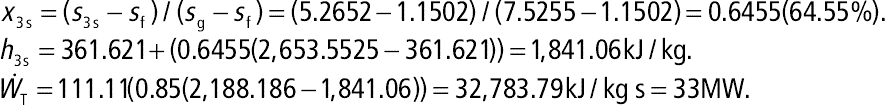
7.2.2.2. Direct dry steam geothermal power plant
If the steam available for the turbine is dry (with quality x = 100%), the steam can directly be fed into the turbine, as in the simplest geothermal power plant. In addition, in order to have a larger enthalpy drop within the turbine, which will give higher power from the turbine, a condenser can be added to lower the turbine exit’s pressure. For this, cooling water is needed to lower the temperature, and therefore the pressure, of the condenser. The condensed water can then be cooled by a cooling tower. Overflow from the basin of the cooling tower can then be released into a river. But since the water is usually still warm and releasing warm water into a river can alter the ecosystem of the river, the overflow water is usually reinjected into a reinjection well. To decrease the cost, the reinjection well can use a low or no production well that is located outside the area of the predicted reservoir. The reinjection well should be far enough from the reservoir to avoid decreasing the temperature of the reservoir in both the short and long terms. The schematic of this direct dry steam geothermal power plant is shown in Figure 7.15. Note that the process for the separator in this figure assumes there is continuous separation of the liquid and steam. If the pressure drop and the blowdown of the separator are negligible, then point 1 on the process diagram should be at the same location as point 3.

Figure 7.15 Schematic and T–s diagrams of a direct dry steam geothermal power plant.
The mass and energy conservation laws of the components of this plant can be written as:
Turbine:
Condenser:

where h8 can be taken as the enthalpy of the saturated liquid at the surrounding pressure and h6 can be taken as the enthalpy of the saturated liquid at the condenser’s pressure.
7.2.2.3. Single flash steam geothermal power plant
For low quality steam, which is mostly water, where quality x equals or is close to zero, the steam cannot be fed directly into the turbine since the water droplets will shorten the lifetime of the turbine blades, especially in the first few stages. To avoid this, low quality of steam can be flashed to a lower pressure and then the produced dry steam can be separated and fed into the turbine, while the saturated water can be reinjected into the reinjection well. The process of the steam after exiting the condenser can be the same as the previous type of geothermal power plant. The ideal thermodynamic process during the flash process can be considered as isenthalpic and the separation process as isobaric, as shown in Figure 7.16.

Figure 7.16 Schematic and T–s diagrams of a single flash steam geothermal power plant.
Thermodynamic analysis of this type of power plant should be similar to the previous ones. Mass and energy balances of each component should be calculated along with power output and the power plant’s efficiency.
7.2.2.4. Double and multiflash steam geothermal power plant
If the low quality steam has sufficiently high pressure, the steam can then be flashed twice. Saturated water from the first flasher can then be flashed again. Saturated steam from the first flasher can be fed into a high-pressure turbine, while the saturated steam from the second flasher can be fed into a low-pressure turbine. Both turbines can be constructed in tandem to give the same rotational speed to turn a generator, or be separated. Since there is more steam fed into the turbine, this configuration will give a higher power output at the expense of a more complicated and expensive system. Theoretically, a triple, quadruple, or multiflash system can be constructed if considered more economical. A schematic diagram of the double flash steam geothermal power plant can be seen in Figure 7.17.
Figure 7.17 Schematic and T–s diagrams of a double flash steam geothermal power plant.
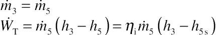
7.2.2.5. Binary or organic Rankine cycle (ORC) geothermal power plant
If the temperature of a supplied geothermal steam is not high enough, say below 200°C, then the steam is usually not economical enough to be used in a steam turbine. Instead, the hot steam, water, or brine can be used to heat a secondary fluid with a lower boiling point, such as organic fluids like propane or butane. The cooled steam or water can then be reinjected into a reinjection well. In the meantime, the organic fluid can be used to create a closed Rankine cycle, usually called ORC to produce work in an organic turbine. Such a turbine is usually physically much smaller than a steam turbine for the same capacity. In the condenser, the working fluid can be cooled by using cooling water or air.
A schematic PFD and process diagram of the OCR can be seen in Figure 7.18. The evaporator can heat the organic fluid until it is a saturated liquid (point 4) or superheated liquid (point 4′). Note that, in retrograde fluids such as n-butane, i-butane, n-pentane, and i-pentane, the right side of the T–s diagram curves, which makes the output of the turbine always in the superheated region.

Figure 7.18 Schematic and T–s diagrams of a binary cycle or ORC geothermal power plant.
7.2.2.6. Kalina cycle
Besides the ORC used in the aforementioned geothermal power plants for low temperature geothermal fluid, a Kalina cycle can also be used. This cycle was developed by Dr Alexander Kalina in the 1970s and uses a solution of two fluids with different boiling points. Although ammonia and water are the two most common working fluids used in the Kalina cycle, other types of fluids can also be used. The closed cycle simply uses low temperature steam, water, or brine from the geothermal well to heat up the working fluid, and cooling water or air to cool it down in closed heat exchangers.
By using two fluids with different boiling points as the working fluid, the solution boils and condenses over a range of temperatures, which gives more heat to be extracted from the geothermal fluid than with a pure working fluid. Depending on the heat input temperature, the range of boiling point of the solution can be adjusted by adjusting the ratio between the components of the solution. As a result, the average temperature of the working fluid in the heating process is higher and the average temperature of the cooling process is lower, thus giving the cycle a higher efficiency. A simple Kalina cycle is shown in Figure 7.19. A more complex Kalina cycle will involve additional separators and recuperators, to gain higher efficiency at the cost of a more complex and expensive system.

Figure 7.19 Kalina cycle used in a 2 MW geothermal power plant in Husavik, Iceland. Adapted from Ref. [12].
Among others, the Kalina cycle is used in the Husavik facility in Iceland, which produces 2 MW of electric power and 20 MW of thermal power, and at the Unterhatching facility in Germany (near Munich) that produces 3.4 MW of electric power and 38 MW of thermal power [12,13].
The Kalina cycle is not only used in geothermal power plants, but can also used to recover heat from other power plants and industrial process plants in processes, where the heating or cooling process occurs in a liquid or gas phase, where the temperature increases or decreases (not during a phase change, where the temperature remains constant).
7.2.2.7. Total flow devices
To gain power from a geothermal fluid, total flow devices can be used to expand the fluid while gaining power to turn a generator. Although the efficiency is usually small, these devices do not usually require additional complex equipment. Examples of these total flow devices are [14]:
1. The Sprankle Hydrothermal Power Company (HPC), Ltd.) prime mover: brine expander
2. The Robertson engine
3. The bladeless turbine (such as the Tesla turbine)
4. The Keller rotor oscillating vane (KROV) machine
5. The Armstead-Hero turbine
6. The gravimetric loop machine
7. Electro-gas-dynamics (EGD)
8. Total flow impulse turbine
9. The biphase turbine
Refer [14] for brief descriptions on these devices.
7.2.2.8. Hybrid systems
In a hybrid system, geothermal heat can be used as a preheat of a fossil fuel power plant. This will reduce the cost of fuel to run the boiler. In another hybrid system, fossil fuel can be used to superheat the geothermal fluid, which will increase the power output and efficiency of the geothermal power plant. Both of these systems require a location where both the geothermal sources and fossil fuels are easily available. The PFD and T–s diagram of these two hybrid systems are shown in Figures 7.20 and 7.21.
Figure 7.20 Hybrid system: fossil fuel power plant with geothermal preheat.
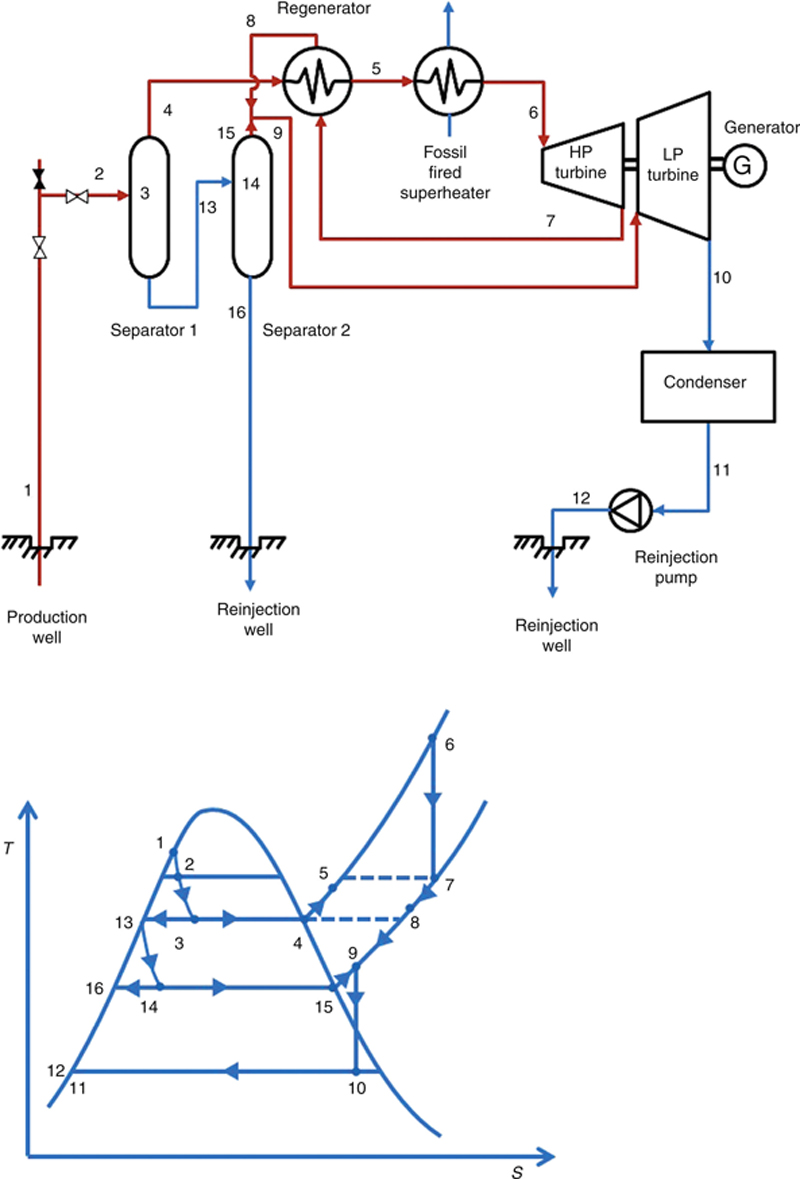
Figure 7.21 Hybrid system: geothermal power plant with fossil fuel superheater.
7.2.2.9. Hot dry rock
HDR, also known as enhanced geothermal system (EGS) in a geothermal system is a condition where water is not naturally present at the site. The magma only heats dry rock on top of it. In order to tap heat from the dry rock, two wells can be drilled into the rock. One well is used to carry water from the surface down into the HDR. Once the water is heated, steam created is then channeled up through the second well into a turbine above the surface (Figure 7.22). The additional installations will be the same as the previous types of power plant discussed: direct dry steam, flash steam, or OCR.

Figure 7.22 Simple diagram of a HDR geothermal power plant.
In order to increase the heat transfer between rock and water, water can be pumped into the rock causing it to hydraulically fracture, or the rock can be control-exploded first. The explosion should create small rocks that can heat the water into steam more effectively. Care should be given so that the explosion does not create cracks that can allow the water or steam to leave the reservoir except through the provided well.
HDR system was used for the first time experimentally in Los Alamos, New Mexico, USA in 1970. The experiment was then followed by similar projects in Australia, France, Germany, Japan, and the United Kingdom [4].
7.3. Evaluation of geothermal power plant
When evaluating the geothermal power plant, power output can be considered as the power of the turbine, or  , as in a regular steam power plant without a pump. On the contrary, efficiency of the plant is not so obvious since the boiler is the earth itself. For that, a new definition of efficiency for a geothermal power plant must be used. There are at least two alternatives, namely
or

where the subscript o is for the dead state condition of the surroundings, usually taken as 1 atm and 25°C.
The last equation is also known as the utilization efficiency [11].
7.4. Summary
The basics of geothermal energy have been covered in this chapter. The definition, possible locations, and types of manifestation of geothermal energy have been described in detail. Direct use of geothermal energy used for heating space, objects, agriculture, farm animals, and aquatic species, have been described. Additional methods such as using a heat pump and absorption cooling were also discussed. The indirect uses of geothermal energy where electricity is generated in geothermal power plants were also covered. Methods of making use of vapor and liquid dominated geothermal sources were discussed. The use of organic fluids in ORC and in the Kalina cycle were also covered. Also use of the total flow devices and how an HDR can be used in a geothermal power plant has been discussed. The chapter concluded with a discussion on how to define the total power and efficiency of a geothermal power plant.
Advance course should include exergy analysis of the plant, analysis of vacuum jet pumps and LRVPs, piping system, cooling tower, handling corrosive fluids, environmental consideration, etc.
Nomenclature
h Enthalphy (kJ/kg)
m Mass (kg)
![]() Mass flow (kg/s)
Mass flow (kg/s)
P Pressure (Pa)
![]() Heat transfer rate (kJ/kgs)
Heat transfer rate (kJ/kgs)
s Entropy (kJ/kgK)
T Temperature (K)
t Time (s)
![]() Power (kJ/kgs)
Power (kJ/kgs)
Subscripts
cv Control volume
e Exit
f Saturated liquid
g Saturated gas
i Inlet, isentropic
s Isentropic
t Turbine
td Dry turbine
tw Wet turbine
Acknowledgment
The author wishes to thank Adi Nuryanto, Maesha Gusti Rianta, Putranegara Riauwindu, and Achmad Refi Irsyad for their contributions to construct the figures used in this chapter.
..................Content has been hidden....................
You can't read the all page of ebook, please click here login for view all page.