Considering the large capital investment and the numerous possibilities for electrical system disturbances, control instrumentation malfunctions, and operator errors that can allow generators to operate outside of their original design specifications, it makes good business sense to apply protective relays that can prevent generator damage during abnormal operating conditions. This chapter will cover the gathering of information needed to calculate protective relay settings, the setting calculations for the various protective functions, typical generator/turbine withstand times for abnormal operating conditions, and the math associated with various types of impedance elements.
A good starting point is to compile the data needed for setting the various generator protective functions. Figures 4.1, 4.2, and 4.3 provide examples of organizing and massaging or converting the information to a more useful form for generators, step-up transformers, and their associated electrical systems. The information is for a 578.6 megavolt-amp (MVA), 24 kilovolt (kV) generator that is connected to the 765 kV bulk power transmission system. Organizing the data in this manner will save significant time in developing and documenting the basis for the relay settings.
The top half of Figure 4.1 shows the generator data needed for the relay settings, including generator nameplate data; the direct axis saturated subtransient, transient, and the synchronous per-unit reactances; and the various primary and secondary instrument transformer ratings. With the exception of converting primary ohms to secondary or relay ohms (as shown in Figures 4.4 and 4.5), the MVA and per-unit conversions were covered in Chapter 2 and will not be discussed further here. The bottom half of Figure 4.1 provides nominal currents, instrument transformer ratios, and various reactance ohms (not per unit) that will be used to develop the settings for the backup impedance, loss-of-excitation, and out-of-step relay functions.
Figure 4.2 presents the step-up transformer secondary or relay ohms for the backup impedance and out-of-step relay functions. The transformer per-unit base impedance at 555 MVA needs to be converted to the generator base of 578.6 and corrected for voltage differences on the generator side of the transformer and tap differences on the high voltage side of the transformer. With the exception of secondary or relay ohms, the per-unit MVA conversions and corrections have already been discussed.
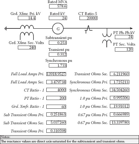
FIGURE 4.1
Generator Data
Figure 4.3 develops the high voltage switchyard secondary or relay ohms for the generator out-of-step function. Normally, this calculation would not include the short circuit contribution from the generator. First, the system kV ohms and volt-amps (VA) are determined, then, the generator side amps and ohms are calculated, and finally, the secondary or relay ohms that represent the high voltage electrical system are developed. The system short circuit angle is not used in the calculation, but is needed for setting the out-of-step protective relay function.
Figure 4.4 presents the expression for calculating secondary or relay ohms. The converse calculation in Figure 4.5 is used to convert relay ohms to primary side ohms.
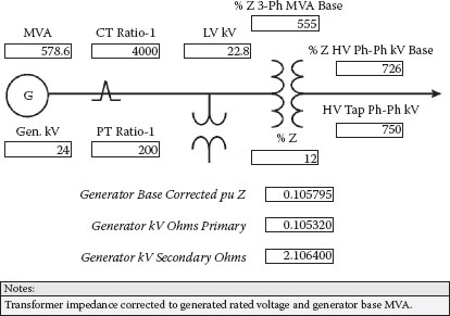
FIGURE 4.2
Transformer Data
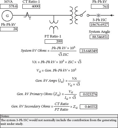
FIGURE 4.3
System Data
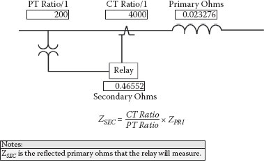
FIGURE 4.4
Primary to Relay Ohms
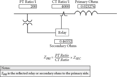
FIGURE 4.5
Relay Ohms to Primary Ohms
4.2 High Voltage Switchyard Configurations
Before delving into the generator protective functions, a review of the associated high voltage switchyards might be appropriate. Figures 4.6, 4.7, and 4.8 illustrate the more common switchyard configurations for handling two lines and one generating unit. In all three configurations, the opening of line breakers to clear faults increases the circuit XL and momentarily reduces the power transfer capability on the remaining line until the power angle changes, as the unit accelerates, to match the output of the turbine.
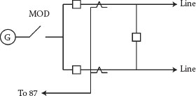
FIGURE 4.6
Ring Bus Configuration
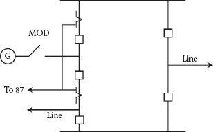
FIGURE 4.7
Breaker and a Half Configuration
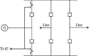
FIGURE 4.8
Double Breaker Double Bus
The Figure 4.6 ring bus configuration is the simplest and least costly. It also has the lowest maintenance costs and exposure to failures because there are fewer components. As the figure shows, only three breakers are required for one generating unit and two lines. Because each element (unit or line) has two breakers, the opening of one breaker does not interrupt power flows. The generating unit position is equipped with a motor operated disconnect (MOD) that can be opened after the unit is taken off-line, permitting the reclosure of the unit breakers to improve the integrity of the ring bus. The 87 differential elements could be for the line from the generator step-up transformer (GSUT) to the switchyard but may also overlap the GSUT to provide transformer protection and, more commonly, will also overlap the generator to back up the generator protection. Schemes that include the generator are called overall differential or unit differential. With overall or unit differential, current transformers (CTs) are normally applied on the auxiliary transformer primary side to balance out any auxiliary load current. In all cases, the 87 differential protection must remain in-service when the unit is off-line (unless both unit breakers are open) because it now provides high voltage switchyard bus differential protection for the two unit breakers and the conductors between the breakers and the open MOD. The main disadvantage of a ring bus configuration is if one breaker is out-of-service for maintenance, a single line fault could interrupt power flow to the other line. Separate bus differential relays are not required, as the unit and line protection overlaps and protects the bus sections.
Figure 4.7 illustrates a breaker and a half configuration. Although this design requires five breakers for one generating unit and two lines, it provides greater electrical system security. This configuration has top and bottom buses that are usually protected by high impedance bus differential schemes. High impedance differential schemes are favored on large buses (multiple lines) to mitigate false operations from error currents associated with unequal CT loading and performance by forcing more of the false differential to flow in the CT circuit and less in the relay. The generating unit position is equipped with an MOD that can be opened after the unit is taken off-line, permitting the reclosure of the unit breakers to improve the integrity of the switchyard. As with the ring bus configuration, the 87 differential elements must remain in-service when the unit is off-line and the unit breakers are closed because it now provides high voltage switchyard bus differential protection for the breakers and for the conductors between the breakers and the open MOD. A second generating unit or a third line can be accommodated with the addition of only one more breaker.
Figure 4.8 displays a double breaker double bus configuration. In this example, six breakers are required for two lines and one generating unit. This provides the highest level of reliability. If a breaker is out for maintenance, a fault on a transmission line will not prevent power flow from the generating unit to the unfaulted line. Each bus section, top and bottom, would normally be protected with a high impedance bus differential scheme. The MOD is not required, as the unit breakers can remain open when the unit is off-line. The addition of another line or generating unit would require two breakers.
4.3 High Voltage Switchyard Protection Concerns
There are a number of concerns with the protection of generating station high voltage switchyards. The main concerns are the clearing of electrical system faults before the unit goes out-of-step and backup protection.
Transmission faults unload the machine because the watt load is displaced by vars. The loss of load accelerates the machine and, at some point, as the power angle and speed differences increase, the unit becomes unstable and can no longer maintain synchronization with the electrical system, which significantly aggravates the disturbance and can cause a major electrical system upset. This is called the critical clearing time and is usually in the range of 6 to 20 cycles, depending on the type of fault and severity. Worst-case conditions can cause electrical system outages and the islanding of loads.
The second issue is backup protection; high voltage transmission lines almost always have backup schemes that are overreaching and do not rely on high-speed communication systems. Figure 4.9 shows a typical transmission line backup protection scheme that utilizes zone 1 and zone 2 directional distance or mho-type impedance relays. Usually zone 1 will trip without time delay and is set for 80% of the impedance ohms of the line. Depending on the length of area transmission lines, zone 2 will be set for 120% of the line impedance or greater, with a typical time delay of 0.4 seconds or 24 cycles for coordination purposes. This time delay usually exceeds the critical clearing time of generating units, and nearby on-line generation will likely lose synchronization with the system before line zone 2 relays can time out to clear faults beyond the lines. It is not unusual to find generating station high voltage switchyard bus differentials, unit differentials, transformer differentials, and feeder differentials that are not backed up and rely entirely on zone 2 clearing if the single protection schemes fail to interrupt bus, transformer, or feeder faults. Additionally, depending on the number of transmission lines in the switchyard, the zone 2 relays and directional ground overcurrent relays at the remote ends of the lines may not be able to detect the faults beyond the lines due to current distribution and infeed ohms.
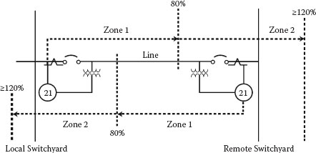
FIGURE 4.9
Transmission Line Backup Impedance Zones
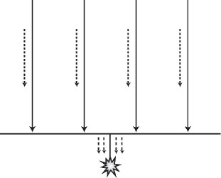
FIGURE 4.10
Fault Current Distribution and Infeed Ohms
Figure 4.10 represents the current distribution and infeed problem. In the case of directional ground overcurrent relays, the amount of ground current in each line is reduced because the fault current is shared by all lines. If nearby generation is also feeding the ground fault, the fault current flowing in each line would be reduced further. The concerns are that the ground protection at the remote ends of the lines may not have enough sensitivity to detect local ground faults beyond the lines, and if they do, the fault clearing timing may be too long to avoid generator instability.
The other issue is infeed ohms, which is more of a problem if different sources are involved because the voltage drops are not congruent with a single source, that is, generating units, ties to other utilities, and more remote substations. Figure 4.11 shows the calculations for infeed ohms with two sources, A and B, with A having a per-unit impedance of 0.5 ohms and an additional 0.5 ohms to the fault location or 1.0 per-unit ohms total if B is not connected. First, the total circuit per-unit impedance and current is determined, then, the current contribution from A only is proportioned, and finally, the per-unit impedance seen by A to the fault location is proportioned at 1.5 per-unit ohms or 150% higher when B is included.
The worst-case location for infeed at a generating station would normally be faults near the high voltage bushings of reserve auxiliary transformers (RATs) that are fed from the same high voltage switchyard. In this case, the zone 2 relays at the remote end of the transmission lines may not be able to detect the fault to back up the RAT transformer differential and/or feeder differential protection. As mentioned before, line zone 2 time delays may be too long to avoid instability problems with the generating units. Additionally, generator protection functions that can see switchyard faults (negative phase sequence and backup impedance) may also have time delays that are too long to avoid instability or loss of synchronization with the electrical system. If the generating unit is equipped with out-of-step protection (many are not), the unit will be tripped off-line and isolated from the fault.
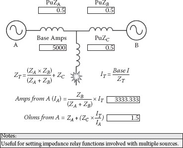
FIGURE 4.11
Infeed Ohms
Usually, high voltage switchyards are equipped with breaker failure schemes that will clear everything necessary to isolate faults if a circuit breaker fails to interrupt the fault current in a timely manner. Normally, two conditions are required: a specified level of fault current and an energized breaker trip coil circuit. If these conditions are met, a timer output will operate to trip the necessary adjacent breakers or units to isolate the fault. It is not unusual to find breaker failure fault clearing times that are longer than the critical clearing time. The fault clearing time includes the initiating relay time, plus the breaker failure time delay, plus the longest breaker trip time, plus the longest breaker interrupting time. Consequently, close by generation may go out-of-step before the breaker failure scheme can isolate or clear the fault.
To counter some of the foregoing problems, it is recommended that zone 1 impedance relays be applied to backup high voltage unit, transformer, and feeder differential relays. The relays measure voltage and current at the generating station switchyard and look into the GSUTs or RATs; the zone 1 relay can be set with a small time delay (3 to 6 cycles) to ensure the differential schemes also operate. In regard to the GSUT, it should be ensured that the impedance relays cannot operate for loss-of-excitation events and cannot see unit auxiliary transformer (UAT) medium voltage faults for coordination. With the RAT transformer, the relay can be set to look halfway into the transformer to ensure it cannot overreach and see medium voltage faults. The advantage of applying impedance elements is they are not dependent on the strength of the electrical system, which varies depending on the number of sources available at the time of the fault. Ohms are ohms, and the impedance of a transmission line or transformer does not change when generating units or lines are placed into or out of operation. Early impedance relays were not directional and consisted of a circle that was symmetrical and encircled the point of origin. These impedance elements were supervised by directional contacts or relays. When directional electromechanical impedance relays were initially developed, the term mho was used, because the torque equations included the reciprocal of ohms. The elements normally encircle the first quadrant, which represents a series current lagging circuit.
4.4 Generator Protective Functions
This section will develop the protective function settings for the 578.6 MVA steam turbine generator and its associated step-up transformer and high voltage electrical system as previously shown in Figures 4.1, 4.2, and 4.3. Many of the electrical protection functions in a generator package are applied to protect the prime mover or turbine and not just the generator. The suggested settings are for 100 MVA and larger two and four pole cylindrical rotor generators connected to typical utility transmission or sub-transmission systems. Slower speed salient-pole generators and smaller units connected to weaker systems or units with different or unusual electrical configurations may present special circumstances that are not covered in this chapter. The following material is presented in numerical order according to the standard device numbers assigned for different relay functions.
The 21 function is a backup impedance relay with one or two zones that look from the generator to the electrical system. The 51V time overcurrent element provides a similar function and it is preferable to apply the 21 backup impedance elements only. The 51V is a voltage controlled or restraint time overcurrent relay that permits setting the minimum trip threshold well below full load amps to allow for generator fault current decrements, but it will not operate unless the voltage is depressed by a fault condition.
No industry consensus exists on how to set the zone 2 impedance function; various papers propose different philosophies involving the shortest or longest line. Most of the papers advocate using the zone 2 function to trip or isolate the unit for close-in high voltage system faults that do not clear quickly enough. Fairly long time delays are necessary to ensure coordination with downstream electrical system protective devices, that is, breaker failure time delays, transformer bank overloads, zone 2 line protection time delays, and so forth. Because of the long time delay, this function may not be able to operate for close-in faults because the unit will likely lose synchronization with the system before the relay can time out. The out-of-step slip cycle can reset and pick up impedance elements as the impedance locus or swing travels through its cycle. Generators are thermally protected from high voltage phase-to-phase and phase-to-ground faults by negative phase sequence relays, but these relays will not respond to three-phase balanced events. Based on the foregoing, it is proposed that the zone 2 element be applied to thermally protect the generator from balanced three-phase prolonged system disturbances. For cross-compound units or generators operated in parallel, the settings will need to be modified to account for infeed impedance.
Figure 4.12 provides suggested settings for two element generator backup impedance relay schemes. Zone 1 is set to reach halfway into the GSUT (1.053 ohms) with a 0.1 second time delay. The short reach eliminates concerns about coordinating with downstream devices, and the short time delay is suggested to allow time for the differential relays to operate first. Operation of a primary relay provides important information about the location of the fault and verification that the relays are performing as designed. If the CTs are on the generator output side, it is customary to offset the mho circle by the direct axis saturated transient ohms to include the generator. If the CTs are on the neutral side, some manufacturers suggest using 0.1 ohms offset to provide some margin. As in revenue metering, the location of the potential transformers (PTs) determines the precise point of measurement because the circuit voltage drops are measured accurately. However, the CT location does have a directional impact on whether or not the event is in a forward (toward the electrical system) or a reverse direction (toward the generator). An angle of 75 degrees is often used to accommodate circuit and arc resistance.
The suggested reach for zone 2 is 150% of the rated generator MVA (.67 per unit) or 13.34 ohms with a time delay of 2.0 seconds to ensure downstream coordination. Because this is a three-phase setting, there is no concern about unbalanced events, and compensation to account for the impact of the delta-wye transformation on unbalanced faults is not required. The suggested offset and angle is the same as the zone 1 setting.
Generators are typically designed to carry 130% of rated stator amps for 60 seconds and 180% for 20 seconds. Accordingly, the foregoing setting of 150% or greater for 2.0 seconds has more than adequate thermal margins. As covered in Chapter 3, transformers can handle 150% for a little over 9 minutes. A 2.0 second time delay is suggested because it is the short circuit electromechanical force withstand time for transformers and it should also coordinate with all downstream protective devices on a typical utility system.
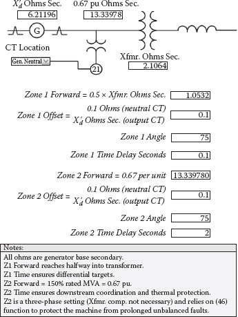
FIGURE 4.12
Generator Backup Impedance Settings
It is doubtful that turbine/generators can provide 150% of rated megawatt load for 2.0 seconds, and utility load shedding programs should operate to bring the megawatt demand back into balance if the watt deficiency is severe enough. Governor droop settings for steam units are usually 5%. This is really control system terminology, but a simplistic way of looking at it is that it takes a 5% speed change to get the control valves fully opened or closed. During an earthquake islanding event in California, a digital fault recorder captured a 215 MW generator that was subjected to twice rated load, and the voltage collapsed to zero in 6 cycles. The general rule of thumb is that generating units should not try to pick up more than 10% of rated MW at any one time. The foregoing discussion on megawatts is really a mute point because the angle is set at 75 degrees (mostly vars) and the ohmic reach would be substantially lower (higher current) at reduced angles. Angles greater than 75 degrees would also need a slightly higher current to operate. For example, at 90 degrees, the reach point would be 12.89 ohms, or about 3.4% lower. However, generators can carry substantial vars that may thermally overload path components during major system disturbances. Since the normal utility system relies on capacitor banks and not generation to carry the system var requirements, excessive var loading for 2.0 seconds would be more indicative of a system fault that did not clear properly. Due to infeed concerns, it is not advised to increase the setting above the 150% MVA level or reduce the ohmic value further.
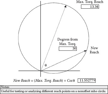
FIGURE 4.13
Mho Circle Reach Points
If the mho circle is not offset, the circle ohmic or impedance points can be calculated by simply taking the cosine of the angle deviation from the circle diameter or maximum reach point, as illustrated in Figure 4.13. The relay will actuate whenever the ohmic value is inside the circle.
Figure 4.14 shows an offset mho impedance circle for generator backup applications. Ohmic values on the circle can be calculated by using the trig method presented in the figure.
This is a very important protection function for generators and connected transformers. The easiest way to catastrophically destroy a generator or its connected transformers is by overfluxing the iron laminations in their cores. The term volts per hertz (volts/Hz) is used because of the impact underfrequency operation has on the level of flux in the core. In the case of transformers, a reduced frequency will lower the exciting impedance, causing a higher exciting current, more ampere-turns, and increased magnetic flux in the core iron. The increased magnetic flux will raise the level of eddy currents in the laminations, which results in higher core iron temperatures and saturation. As the laminated iron saturates, the magnetic flux will spill into structure areas that are not designed to carry flux, and those areas will also overheat from eddy currents. In the case of generators, the core iron flux is not a direct function of frequency or speed, and the no load DC field is safe over the entire speed range. However, a generator is like a tachometer: the slower the generator’s speed, the lower the output voltage. If the automatic voltage regulator is in service, it will try to correct for the reduced output voltage by increasing the DC field current, which can overflux the core iron depending on the amount of voltage regulator correction. Consequently, the expression volts/Hz will work equally well for generators and transformers. Generators are normally designed to carry 105% of rated voltage continuously and transformers 110% at no load and 105% at full load, but credit can be taken for the internal voltage drop in transformers. Accordingly, the generator volts/Hz relays will normally provide protection for connected transformers, depending on the load currents, voltage drops, and rated winding voltages. The continuous rated frequency voltages of 105% or 110% are also the continuous volts/Hz ratings for the apparatus.
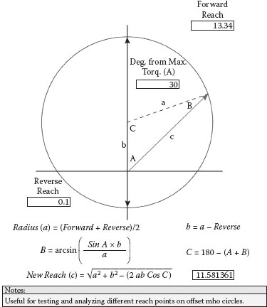
FIGURE 4.14
Offset Mho Circle Reach Points
This protection is essential at generating stations because of the numerous ways that overexcitation can occur through operating mistakes or equipment failures. Although many generator voltage regulators are equipped with volts/Hz limiters and some are equipped with volts/Hz tripping logic, normal practice is to provide volts/Hz protection in a separate package over concern that there may be common modes of failure that can impact the voltage regulator control as well as its protective functions. The short time withstand capabilities of the apparatus for severe events does not allow time for operator interdiction before catastrophic damage can occur. During startup, in some designs, excitation is applied at very low speeds, which is no problem, as mentioned earlier, as long as the automatic voltage regulator is out of service and the no load field current is not exceeded by more than 5%. As a generator is loaded, its DC field is increased to compensate for internal voltage drops and the subtractive flux (armature reaction) from the higher current flow in the stator windings. Depending on design details, the no load field current is somewhere in the neighborhood of 50% of the full load field current. Typically, a generator can withstand a full load field with no load on the machine for only 12.0 seconds before damage occurs to the core iron. The typical withstand at 115% volts/Hz is around 5.0 minutes. The shape or slope of the withstand curves for generators and transformers are usually similar, with the main difference being the continuous rating starting points.
Figure 4.15 covers the procedure for calculating the impact of operating generators at abnormal voltages or frequencies. For reference, the maximum primary and secondary 60 cycle voltages are calculated. A base volts/Hz ratio is determined by dividing the rated kV by the rated frequency. An applied volts/Hz ratio is then determined by dividing the applied kV by the applied frequency. The actual or applied volts/Hz percentage can then by determined by dividing the applied ratio by the base ratio and multiplying by 100. In this example, the generator’s continuous volts/Hz rating of 105% is significantly exceeded with a calculated percentage of 115% even though the applied voltage of 23 kV is well below the 60 Hz maximum rated voltage of 25.2 kV.
Figure 4.16 shows the procedure for calculating the impact of operating the GSUT at the same voltage and frequency values used in the prior example for the generator. In this case, although the maximum rated 60 cycle voltages for the generator and transformer are both around 25 kV, the underfrequency event is a little more severe for the transformer with a higher volts/Hz percentage of 121% compared to only 115% for the generator. This is because the base ratio for the transformer is lower due to the reduced kV rating of its primary winding.
Figures 4.17 and 4.18 illustrate the Westinghouse overexcitation withstand curves for generators and transformers respectively. Although these curves tend to be a little more conservative than some manufacturers’ curves, they are all in the same ballpark. Upon examining the generator curve, you will find that the generator can withstand the Figure 4.15 volts/Hz percentage of 115% for 5 minutes. The generator curve is flat at 125% and greater with a withstand time of only 0.2 minutes or 12 seconds. The connected transformer, however, is experiencing a volts/Hz percentage of 121% and the associated withstand time extrapolated from the transformer curve is about 4.5 minutes. Therefore, in this case, the transformer is a little more limited.
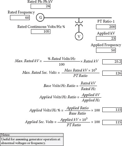
FIGURE 4.15
Generator Volts/Hz
Figure 4.19 provides suggested settings for a three element volts/Hz protection scheme. The first element is set to alarm at 106% or 1 percentage point above the continuous rating. The second element is for a curve with a minimum pickup point of 106% and a time delay of 45 seconds at 110%, and the third element has a minimum pickup point of 118% and a fixed time delay of 2.0 seconds. This setting complies with General Electric (GE) recommendations and has more than ample thermal margin to ensure protection of their machines. Consequently, in this case, it will protect both the generator and connected transformer under study. Experience has shown that the proposed settings will not cause nuisance tripping on a normal utility system; the suggested settings were applied by a large generation company that had experienced major generator damage on two machines from overexcitation and did not want to push the thermal margins. Although overfluxing the iron core is considered, a thermal event with time delays before damage, a large generator manufacturer did experience an almost instantaneous failure in their test pit. The iron is stacked on key-bars and an overfluxing event caused enough of a potential difference between bars to push high damaging current through the back iron area.
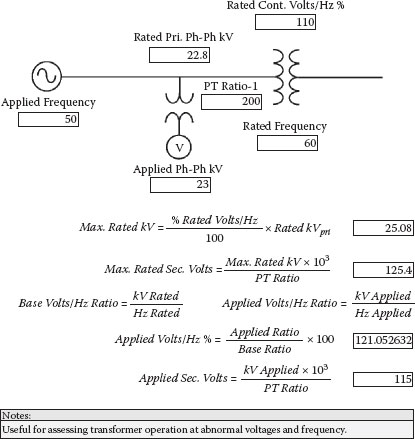
FIGURE 4.16
Transformer Volts/Hz
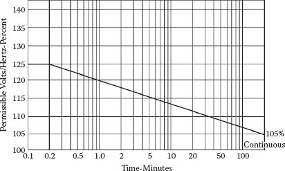
FIGURE 4.17
Westinghouse Generator Volts/Hz Withstand Curve (Used with permission of Siemens Energy, Inc.)
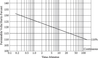
FIGURE 4.18
Westinghouse Transformer Volts/Hz Withstand Curve (Used with permission of Siemens Energy, Inc.)
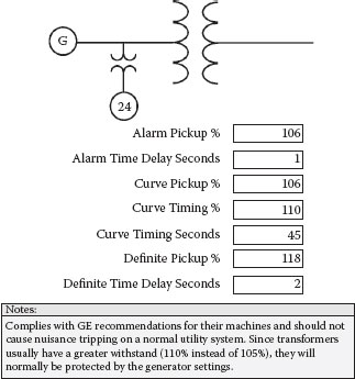
FIGURE 4.19
Volts/Hz Settings
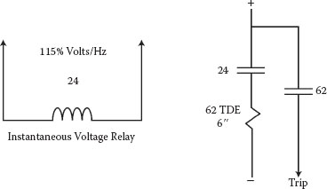
FIGURE 4.20
Simple Single Element Volts/Hz Tripping Scheme
Figure 4.20 covers a simple yet effective single element volts/Hz tripping scheme that utilizes an instantaneous plunger-type electromechanical voltage relay. The relay coil will mimic a volts/Hz function since the ampere turns increase as the frequency is reduced from lower impedance, which results in a lower actuation or trip point. Because only one element is provided, the suggested setting is 6.0 seconds at 115%. The withstand times below 115% are greater than 5 minutes and operator interdiction should be able to protect the machine. Since 6.0 seconds is well under the 12-second withstand time for severe events the setting provides more than adequate protection margins for events 115% and higher.
Good practice is to have the automatic voltage regulator (AVR) fed from a different set of potential transformers than the volts/Hz protection. The volts/Hz relays cannot operate if they do not receive potentials due to blown fuses or an operating failure to rack-in the potential transformers or install the fuses. Depending on design details, if the AVR is on the same potential transformers as the volts/Hz relays, partial or full loss of potentials can cause the AVR to go into a full boost mode and the volts/Hz protection may not be able to operate depending on which phases are impacted by the loss of voltage and where the relays are connected. Volts/Hz is more of a problem during startup because of the underfrequency operations prior to synchronizing. Depending on the design details of the particular excitation system, volts/Hz excursions well over 140% are possible. If the excursions are high enough, auxiliary transformers are likely to saturate and trip on differential protection. There have also been cases where generating units have been tripped off-line while connected to the electrical system as a result of overexcitation levels that have exceeded 115%.
Another relatively easy way to damage a turbine/generator is to synchronize or parallel out of phase with the electrical system. Out-of-phase synchronizing operations can damage or reduce the remaining life of turbine/generator rotors and stationary components. Angular differences as little as 12 degrees can instantly apply 1.5 per unit or 150% of full load torque on the turbine/generator shaft system. The 1.5 per-unit value was measured by a shaft torsional monitoring data acquisition system (EPRI project) at a large coal plant that was paralled to the 500 kV bulk power electrical system with a 12-degree angular difference during synchronization. Plant operations acknowledged that the turbine deck really shook. Although turbines are generally built to withstand angular differences above 10 degrees, most manufacturers recommend limiting out-of-phase synchronizing operations to no more than 10 degrees maximum. Generator sync-check relays should supervise both manual and automatic modes of operation to prevent turbine/generator damage from operator errors or from malfunctioning automatic synchronizing relays. For this reason, it is normal practice to have the sync-check relay function provided in a different package than the automatic synchronizing relay to avoid failure modes that can impact both functions.
A clockwise rotation of the synchroscope in the majority of designs indicates that the turbine/generator has a higher speed or frequency than the electrical system. This condition is desirable to reduce the possibility that the unit will be in a motoring mode of operation and trip on reverse power protection when the breaker is closed. The voltages should be matched during synchronizing with a slightly higher generator voltage to ensure var flow into the system instead of the generator.
Figure 4.21 provides suggested settings for generator sync-check relays. The proposed default angles are 5 degrees advance and 5 degrees late. The calculations consider circuit breaker closing times and maximum allowable slip rates and determine the minimum seconds per scope revolution and the worst-case angle. The minimum seconds per scope revolutions is provided as a guide for operations or for setting auto synchronizing relays; the scope revolutions cannot go faster and be within the operating range of the sync-check relay. The worst-case angle assumes the breaker close signal is dispatched at the maximum late angle and that the breaker XY control scheme seals in. It then looks at the maximum allowable slip frequency (proposed setting of .05 Hz) and calculates the worst-case out-of-phase angle when the breaker contacts actually close. In this case, the worst-case angle of 8.6 degrees complies with manufacturer’s recommendations not to parallel if the angle exceeds 10 degrees. Experience has shown that the proposed settings are practical and within the operating capability of most turbine-governor control systems.
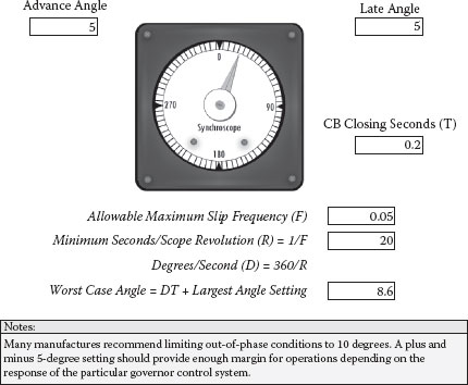
FIGURE 4.21
Synchronizing Check Relay Settings
Other available settings in the newer digital relays might include ratio correction factors for GSUT taps because generator potentials are normally compared to switchyard high voltage potentials and allowable percent voltage mismatches. Although this writer is less concerned about var flows from voltage differences because they do not represent real power and the shaft torques are minimal, plant operators should limit voltage mismatches to less than 5%.
Some of the newer digital sync-check relay functions also include slow breaker protection. Once the breaker control signal is dispatched, it seals in, and there is no way to abort the close operation because there is a 52a contact in series with the trip coil that prevents the coil from being energized until the breaker is actually closed. The slow breaker function could be set to operate breaker failure relaying to clear the adjacent breakers if the angular differences reach 10 degrees or more, indicating that the breaker is slow to close for mechanical reasons.
The maximum amount of symmetrical AC current that flows during synchronizing at rated frequency can be approximated by the expression in Figure 4.22. Generator side voltage and ohms from Figures 4.1 and 4.2 were used in the calculation and reflected to the 765 kV side. The system three-phase 765 kV short circuit ohms were transferred from Figure 4.3. Figure 4.22 shows that the 765 kV current would be approximately 983 amps and the generator amps would be approximately 32,348 at 30 degrees. At 60, 90, and 180 degrees, the approximated 765 kV currents for the parameters presented in the figure would be 1897, 2682, and 3793 amps, respectively. The generator side current at 180 degrees out would be around 124,767 amps. This does not include the DC component or peak asymmetrical current, which will also be present. Obviously, the generator and transformer windings need to be able to handle the peak electromechanical forces. The event is transitory in nature as the asymmetrical current decays and the generator pulls into step with the system and the power angle becomes congruent with the prime mover. The air gap torque is difficult to calculate and depends on electromechanical forces, circuit resistance, and the amount of power transfer from angular differences. Possible damage assessment is particularly complicated and associated with the peak torques and the natural frequencies of the shaft and other mechanical components as the event decays. The associated apparatus may have reduced life from other events or excursions, startup/shutdown cycles, or design or repair oversights, and major equipment damage may occur if the incident is severe enough.
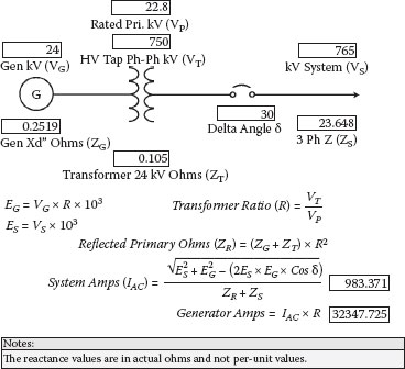
FIGURE 4.22
Maximum Symmetrical Synchronizing Current
Reverse power protection for steam turbine generators is normally applied to protect turbine blades from overheating. The longer low-pressure blades can overheat from windage in the absence of steam flow. Withstand times for steam turbines in a motoring mode of operation are usually in neighborhood of 10 minutes. Motoring is not harmful to generators as long as the proper level of excitation or DC field current is maintained. Steam turbines generally consume around 3% of their rated MW when motoring. This function is sometimes used on combustion turbines for flameout protection and to limit watt consumption from the electrical system, as motoring power is usually much greater for combustion turbines. With hydro turbines, there is concern about blade cavitations during conditions of low water flow.
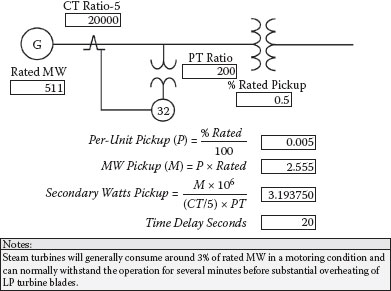
FIGURE 4.23
Reverse Power Relay Settings
Some designs have reverse power supervision of unit breakers to mitigate the possibility of overspeed conditions, and others use reverse power permissives in their automatic shutdown circuitry to delay opening unit breakers until the unit is in a motoring condition. Figure 4.23 calculates the setting for a reverse power relay that is applied to protect steam turbine LP blades from overheating. Because the actuation point needs to be well below the unit motoring requirement, a minimum pickup point of 0.5% of turbine rated MW (3.19 watts secondary) with a time delay of 20 seconds is suggested. The suggested time delay is provided to reduce the possibility of nuisance tripping during synchronizing operations. Since the withstand times are so long, an argument can be made for even more time delay, but many in the industry will opt for a shorter time delay of 10 seconds or less. In the case of combustion turbines, the time delay may need to be reduced if the relay also provides flameout protection. The suggested settings should be compared to the turbine/generator manufacturer’s motoring data to ensure that adequate margins are provided.
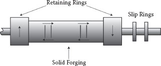
FIGURE 4.24
Cylindrical Generator Two-Pole Rotor Slip Frequency Currents
Loss of field relays are applied primarily to protect synchronous generators from slip frequency AC currents that can circulate in the rotor during underexcited operation. Underexcitation events are not all that uncommon; consequently, this is a relatively important function. Generators can lose field or operate underexcited from a variety or reasons, for example, voltage regulator or power electronic failures, loss of excitation power supplies, opening of the laminated main leads under the retaining rings, opening of the DC field circuit breaker, arcing at the slip rings, differences between system and generator voltages when the voltage regulator is on manual, and so forth.
Figure 4.24 illustrates a cylindrical two-pole generator rotor and the associated slip frequency currents during loss of excitation. Because a two-pole machine rotates at 3600 RPM, the centrifugal force is very high. The figure shows a pole face (opposite polarity on the other side); the field turn slots cannot be seen in this view and would be located at the top and bottom areas. The copper field turns are contained in the forging slots by aluminum or steel wedges that are in a dovetail fit. The circumferential slots in the pole face area are provided to equalize rotor flexing. The retaining rings at each end contain the copper end turns, which are under stress from the rotational forces.
Synchronous generators are not designed to operate as induction machines and are not very good at it. Steady state instability happens when the generator slips poles, which occurs when the power angle exceeds 90 degrees, as shown by the dashed line in Figure 4.25. This occurs because the magnetic coupling between the rotor and stator is weakened by the event and eventually becomes too weak to maintain the output power, and synchronization with the electrical system is lost when the machine speeds up. The speed differences cause induced slip frequency currents (0.1% to 5% depending on initial load) to flow in the rotor body. The circulating currents can be damaging to the highly stressed retaining rings, circumferential slots, forging, and wedges. Although thermal damage from the slip frequency currents is the primary concern, they also cause pulsating torques that can impact the life of mechanical components. The output power on average is about 25% at full load; the var increases typically create stator currents in the range of 114% to 213% that can cause thermal damage to the stator windings after 20 or more seconds.
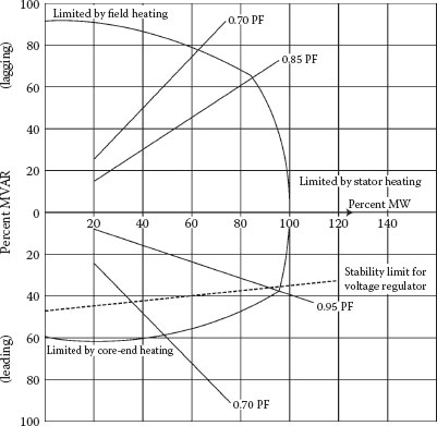
FIGURE 4.25
Generator Capability Curve
In addition to instability, the generator capability curve in Figure 4.25 shows the operating limitation of a typical generator at rated hydrogen pressure. The lagging area represents overexcitation, or boost vars, and the primary limitation is field winding overheating from the increase in field current I2R losses. The leading area represents underexcitation, or buck vars, and is limited primarily from flux impingement of the core iron end packets. The stator core iron is divided into laminations in the direction of the rotor magnetic flux linkage to reduce eddy current losses. However, the rotor end turns beneath the retaining rings change the direction of the rotor flux, and it links with the stator core end iron at right angles, creating higher eddy current losses. The leading var flow in the stator winding also produces a flux that adds to the rotor end turn flux, aggravating the problem. Many large generators are equipped with flux shields at the core ends under the end windings and have increased bore diameters near the retaining rings to protect this area during operation.
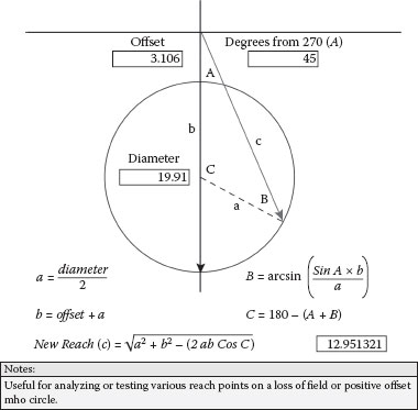
FIGURE 4.26
Loss of Field Mho Circle
Loss of field relays will operate for impedance swings that are inside their mho circles. Normal practice is to positively offset the mho circle by one-half the generator transient reactance ohms, as shown in Figure 4.26, to avoid stable swings that may get into this area during system disturbances and faults. Underexcitation will cause the generator to absorb lagging vars from the system (quadrant 4) that appear to be leading if the reference direction is watt flow from the generator to the system. Under normal operating conditions, generators supply watts and lagging vars to their associated step-up transformers and operate in the first quadrant. The figure also shows the trig calculation procedure for determining the ohmic value of different reach points on the mho circle.
Figure 4.27 illustrates an impedance swing caused by a loss of field event at full load. It starts out in the first quadrant in the load range and then swings into the impedance circle. It can take seconds (2 to 8 seconds) to enter the mho circle, where it will continue to move and eventually exit the circle (1 to 10 seconds later) depending on the associated parameters, and then repeat the slip cycle. The load on the unit at the time of the loss of field event impacts the impedance locus of the event. The higher the load, the faster the impedance swing. Several other factors also impact the impedance locus, including strength of the electrical system, turbine/generator inertia constants, and type of event (shorted or open field circuit).
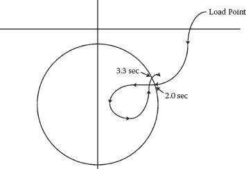
FIGURE 4.27
Loss of Field Impedance Swing
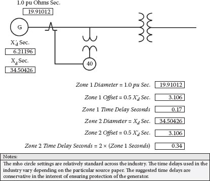
FIGURE 4.28
Loss of Field Relay Settings
Figure 4.28 provides the suggested settings for a two-zone loss of excitation scheme. Both zones are offset by the same amount (3.1 ohms or one half the generator transient reactance). The suggested diameter for the zone 1 circle is 1.0 per unit or 19.9 ohms with a time delay of 0.17 seconds. The suggested diameter for the zone 2 circle is the generator synchronous reactance or 34.5 ohms with twice the time delay or .34 seconds. The suggested offset and mho circle diameters are quite standard across the industry. If only one zone of protection is applied, the zone 2 reach with the zone 1 time delay is recommended. However, the recommended time delays for two zones of protection differ, depending on the particular source paper, from as little as no time delays for zone 1 to as much as 1.0 second or longer for zone 2. For many years standard practice was to apply an electromechanical loss of field mho impedance relay with only one zone of protection that was set according to zone 2 in Figure 4.28, but with a built-in time delay of around 0.17 seconds. This setting did an excellent job of preventing rotor damage and did not cause nuisance tripping. Because the zone 2 mho circle represents a less severe event, doubling the time delay seems reasonable. If the time delay is too long, the impedance swing could exit the mho circle before the function can time out.
4.4.6 Negative Phase Sequence (46)
Negative phase sequence protection is applied to protect generators from reverse rotation double frequency currents that are induced into the rotor if the stator currents are not balanced (Figure 4.29). Significant unbalances can result from a circuit breaker pole that does not make, or a phase conductor that is open prior to, energization. It also provides thermal protection for system phase-to-phase and phase-to-ground faults that do not clear properly. System ground faults look like phase-to-phase faults to generators that feed delta-wye step-up transformers. However, because the negative phase sequence tripping time delays are quite long, the unit may lose synchronization and go out of step before the negative phase sequence relay can operate. As with loss of field, these currents can cause thermal damage to the retaining rings, wedges, and other rotor components and are potentially more damaging than loss of field induced slip frequency currents because the much higher frequency of 120 Hz causes the current to concentrate more on the outside surfaces (skin effect). The reverse rotation induced rotor currents also produces a slight negative torque resulting in torsional oscillations.
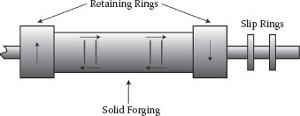
FIGURE 4.29
Negative Phase Sequence 120 Hz Reverse Rotation Induced Currents
Per ANSI/IEEE standard C50.13, generators are rated for both continuous and short time thermal capabilities for carrying negative phase sequence currents. The ratings vary depending on the size of the generator and whether or not it is directly or indirectly cooled. Directly cooled generators have gas or water passages that cool the stator conductors and special gas passages or zones that cool the rotor windings. Cylindrical rotor and salient pole generators equipped with amortisseur windings rated 960 MVA and smaller will have a continuous rating of at least 8% per standards. Salient pole generators with amortisseur and indirectly cooled cylindrical rotor machines will have a continuous rating of 10%. All generators rated 800 MVA and smaller will have a short time 1.0 per unit I2T negative phase sequence thermal rating or “K” of at least 10. Indirectly cooled cylindrical rotor machines will have a K of 20 and salient pole generators a K of 40. In general, smaller and indirectly cooled machines will have a greater thermal capacity for negative phase sequence because the direct cooled machines have a relatively larger capacity or MVA and the cooling system is not as effective for the rotor. Generators larger than 800 MVA will have a reduced thermal capability to carry negative phase sequence rotor currents. Although tripping from this function is rare on large utility systems, negative phase sequence protection is almost always provided due to the thermal limitations of generator rotors.
Figure 4.30 shows full load amps (13,919) on A and B phases and zero current on C phase. This is really an A-B current; consequently, the A-phase angle is shown at 0 degrees and the B-phase angle at 180 degrees. To resolve the symmetrical component negative phase sequence I2 current magnitude, the angle for B phase needs to be advanced by 240 degrees and the angle for C phase by 120 degrees. After the angular advancements on B phase and C phase, the negative phase sequence magnitude of 8036 can be determined by dividing the vector sum by 3.
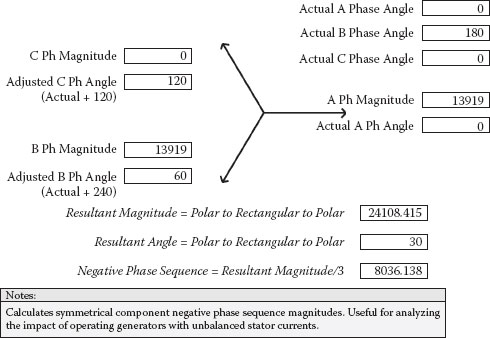
FIGURE 4.30
Negative Phase Sequence Magnitude
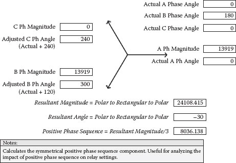
FIGURE 4.31
Positive Phase Sequence Magnitude
As a matter of interest, Figure 4.31 covers a similar process for determining the positive phase sequence magnitudes. For positive phase sequence, the B-phase angle is advanced by 120 degrees and the C-phase angle by 240 degree. As shown, for phase-to-phase events, the positive and negative components are equal to each other.
Also as a matter of interest, Figure 4.32 shows the calculation for the symmetrical zero phase sequence component. The zero phase sequence magnitude is simply the vector sum of actual angles (no angular advancement) divided by 3. In this case, the vector sum is zero, as A and B phases are displaced by 180 degrees. Accordingly, a phase to phase event does not contain a zero phase sequence component.
The generator withstand is based on the symmetrical component method of calculating negative phase sequence current. Figure 4.33 calculates the generator withstand time before rotor damage can occur and discloses that the 578.6 MVA generator can withstand 8036 amps or 57.7% of negative phase sequence I2 stator current for 30 seconds before loss of life or rotor damage starts to occur.
The proposed negative phase sequence settings for the 578.6 MVA generator are presented in Figure 4.34. The suggested alarm and trip pickup points are 6% alarm and 8% trip. The suggested relay timing is for an I2T or K value of 9 (90% of the rotor thermal rating is used up). These settings should not cause nuisance tripping or coordination problems on a normal utility system.
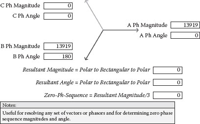
FIGURE 4.32
Zero Phase Sequence Magnitude
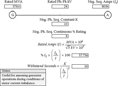
FIGURE 4.33
Negative Phase Sequence Withstand
4.4.7 Inadvertent Energization (50/27)
Inadvertent energization of at-rest generating units is not all that uncommon. This can occur if unit switchyard disconnects that isolate units from energized ring buses or breaker and half configurations are inadvertently closed or if the unit breakers are closed when the isolating disconnects are closed. Some utilities install mid-position limit switches that will trip the associated high voltage breakers open when the disconnect swing hits the mid-position. Although a properly designed sync-check relay scheme should prevent inadvertent closures of generator breakers or unit switchyard breakers, one way or another, it seems to happen in the industry. If the inadvertent energization is long enough in duration, catastrophic generator damage can occur. Inadvertent energization can also occur through the UAT, but the current is much lower because of the relatively high auxiliary transformer impedance, and the auxiliary transformer overcurrent relays should be able to mitigate damage to the unit. During major outages, there is also concern that protective functions that might limit the duration may be out of service for relay testing purposes, or the potential transformers could be racked out or otherwise disabled.
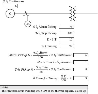
FIGURE 4.34
Negative Phase Sequence Relay Settings
Basically, the unit is being started across the line as a motor. Generators are not designed for this purpose, and severe overheating of stator and rotor components can occur. Additionally, the rotor wedges and amortisseur interfaces (where applicable) will not be held securely by centrifugal force, as they are during normal operation, and the loose fits can cause additional damage from arcing.
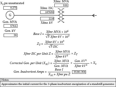
FIGURE 4.35
Inadvertent Energization Current
Figure 4.35 approximates the expected symmetrical current from energizing an at-rest machine. The base current is derived from the transformer MVA. The three-phase short circuit current on the 22.8 kV side of the GSUT is converted to ohms and then to per-unit ohms. The corrected generator unsaturated negative phase sequence per-unit impedance X2c can then be added to the transformer 22.8 kV short circuit per-unit impedance and divided into the base current to determine the at-rest energization current. In this example, the initial inrush current will be around 33,241 amps or 239% of full load amps. In-service loss of field, reverse power or anti-motoring, and generator and switchyard backup impedance relays may be able to see the event depending on their specific settings.
If the generator negative phase sequence reactance is not available, the per-unit value can be approximated by summing the direct and quadrature per-unit subtransient reactances and dividing by 2 as shown in Figure 4.36.
Newer microprocessor-based relays generally have logic functions that detect and trip for inadvertent energization conditions. This logic usually involves recognizing that the unit is off-line by the absence of voltage for a specified period of time and then measuring a sudden inrush of current.
For designs that apply a breaker at the generator bus, some of the newer digital relays provide logic elements that can be mapped to provide breaker failure protection for events that are normally isolated by opening the generator breaker. As with high voltage switchyard breakers, three logic elements are necessary, a specified level of current, an energized breaker trip coil circuit, and a time delay that is longer than the breaker trip time with margin. Tripping would include the unit, associated high voltage breakers, and low voltage auxiliary transformer breakers.
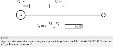
FIGURE 4.36
Negative Phase Sequence Reactance
Although high voltage unit breaker pole flashover is more likely during synchronizing operations where double voltage can exist as the synchroscope rotates, pole flashover can occur anytime the circuit breaker dielectric degrades from moisture intrusion, contamination, or a reduction in dielectric gas pressure. However, energizing an at-rest generator from a pole flashover would have the likelihood of being more damaging than a more transitory event where the generator is at or near synchronous speed. An at-rest machine will not rotate with a single-phase energization, and centrifugal force is not holding the rotor components securely, increasing the possibility of arc damage. Figure 4.37 illustrates the current flow paths on both sides of the GSUT for a C-phase pole flashover event and covers an approximation procedure for determining the high and low side currents into an at-rest generator. First, the generator per-unit negative phase sequence unsaturated reactance (corrected to transformer MVA and low side voltage), the transformer %Z (for the wye winding or 765 kV side), and the high voltage system ground fault current are converted to ohmic values. Then double the corrected generator negative sequence ohms (accounts for current flow into both A- and C-phase windings) are reflected to the system side of the GSUT. The total circuit high voltage side ohms would be the summation of the secondary side reflected ohms plus the transformer high side ohms plus the neutral reactor ohms plus the system ground fault ohms. The neutral symmetrical current can now be determined by dividing the system phase-to-neutral voltage by the total ohms. The transformer neutral current multiplied by the transformer winding turns ratio provides a generator side current of 23,683 amps or 170% of rated generator amps.
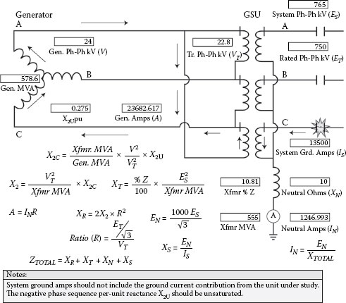
FIGURE 4.37
Pole Flashover Current
Normally, unit breaker pole flashover is detected by sensing GSUT neutral current and 52b logic that indicate that the unit breakers are open. Because the high voltage unit breakers are already open, it is necessary to initiate breaker failure protection to isolate the faulted circuit breaker. Where two unit breakers are involved, breaker failure logic should be able to determine which breaker has the current flow and trip, accordingly. Pole flashover is not of major concern with generator bus breakers because the ground current would be limited by the high impedance stator grounding scheme.
As the name implies, this function operates for generator 60 Hz overvoltage. Because the volts/Hz function also covers 60 Hz overvoltage, this writer does not normally place the 59 function into service.
Normal practice is to prevent nuisance tripping from blown potential transformer fuse conditions. Older electromechanical relays compare one set of potential transformers to another set and block tripping of voltage sensitive relays that might actuate if the two sets of potential transformer outputs are not balanced. Newer digital schemes look at only one set of potential transformers, and if there is a 10% reduction in voltage with no change in generator current flow, a blown fuse is assumed; in addition to alarming, the 60 function will normally block tripping of the 21, 40, 50/27, 51V, and 78 functions. Protective functions that operate on increased voltages would not require blocking for blown fuse conditions and the under- and overfrequency elements normally require a minimum voltage for measurement purposes.
Generator stator ground protection is applied to protect generator stators and all other directly connected electrical apparatus on the output side from ground faults. This can include the primary windings of the main step-up, auxiliary and excitation transformers, associated buses, the generator bus circuit breaker, instrument transformers, and surge capacitors and arrestors. As discussed under the high impedance grounding section of Chapter 3, a grounding transformer is connected between the generator neutral and the station ground grid. High impedance (resistance) grounding is preferred because generators are not typically designed to carry large unlimited close in ground fault currents. The generator stator ground overvoltage relay is connected on the secondary side of the grounding transformer. This function is sometime referred to as a 59G instead of 64.
Relays used for this purpose are normally desensitized to the third harmonic voltages that appear on the neutral when the machine is energized. The voltages are caused by nonsymmetry in the core iron flux, which allows some areas to saturate as the sine wave approaches maximum. The saturation has an imperceptible flattening affect on the sine wave peak that produces the small third harmonic voltage at the generator neutral. The third harmonic frequency (180 Hz) timing is such that the contribution from each phase adds up in a manner to produce a continuous single-phase 180 cycle voltage. For simplicity, the generator can be visualized as a 180 Hz single-phase machine with distributed capacitance at each end, as illustrated in Figure 4.38. This allows the third harmonic current to flow through the output side capacitance and then through the grounding transformer and neutral capacitance in parallel to complete the circuit. Normally, only a few volts of third harmonic will appear on the secondary side of the grounding transformer. The exact level depends on generator design details and will vary as the machine is loaded with watts and vars. The absence of a third harmonic voltage would indicate that either the machine has a ground on the neutral end of the winding, or it has an open or short in the primary or secondary ground detection circuitry. Consequently, it is a good idea to monitor the third harmonic voltage to prove that the ground detection scheme and generator are healthy.
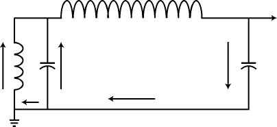
FIGURE 4.38
180 Hz Neutral Current Flows
Because the stator ground protection does not have the sensitivity to detect grounds that are located near the neutral (about 10% of the winding), schemes are available to trip or alarm on the loss of third harmonic voltage. The primary concern is that shorted stator turns near the neutral end will eventually degrade to ground faults from the high temperatures generated by the shorted turn current flow. This is much more of a problem for the slower speed salient pole hydro generators. The salient pole generators are designed with multiturn stator slots (similar to large induction motors) that have relatively small levels of insulation between turns. Cylindrical rotor generators are designed with only two turns in a slot, and each turn has the full ground wall insulation capability, as illustrated in Figure 4.39. Accordingly, it is virtually impossible for transient voltages to cause turn-to-turn failures in cylindrical rotor generators and, consequently, most two and four pole machines are not equipped with surge capacitors. Some utilities trip on loss of third harmonics for hydro machines and alarm only for their two and four pole cylindrical rotor generators. Additionally, the ground wall insulation on a generator is not graded, and the neutral end, which operates at zero to approximately 10% voltage, has the same ground wall insulation (typically 95 kV BIL) as the output end, which operates at 100% voltage. Normal practice is to set the loss of third threshold at 50% of the no load third harmonic voltage. There have been cases with the 50% setting where loss of third harmonic protection schemes have tripped units off-line that were bucking vars or underexcited. Accordingly, it is preferable to alarm only for loss of third harmonic voltages on cylindrical rotor machines with an operating procedure that requires that the unit be taken off-line if an investigation discloses that the primary and secondary ground detection circuitry appears to be normal, that is, stator ground circuit disconnects closed, grounding transformer racked-in, var output is boosting or shipping vars to the step-up transformer, and there is no measurable third harmonic voltage.
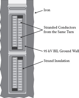
FIGURE 4.39
Cylindrical Rotor Generator Stator Coil Indirectly Cooled Construction
Generating stations built before the 1970s generally used open delta potential transformers for measuring bus potentials. Newer station designs usually apply wye-wye potential transformers to improve the integrity of the isolated phase buses. Each potential transformer is connected phase to ground, which negates the need to bring two different phases into the same segregated potential transformer compartment, maintaining the isolation and reducing the possibility of generator phase-to-phase faults. However, wye-wye connections with both primary and secondary neutrals grounded allows the stator ground protection scheme to detect secondary side ground faults. Either the stator ground protection time delay may need to be increased (at the risk of iron damage) to coordinate with potential transformer secondary side fuses, or the grounding method at the secondary side needs to be changed. Instead of grounding the secondary neutral point, one of the phases could be grounded with the neutral floating, as illustrated in Figure 4.40. The stator ground scheme can now only see faults between the secondary neutral and the grounded phase; because the neutral wiring is only between the transformer compartments, the exposure is quite low and a fault to the neutral is unlikely. The foregoing assumes that a grounded secondary side neutral is not required by the particular relays applied for generator protection.
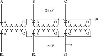
FIGURE 4.40
Modified Wye-Wye Potential Transformer Grounding
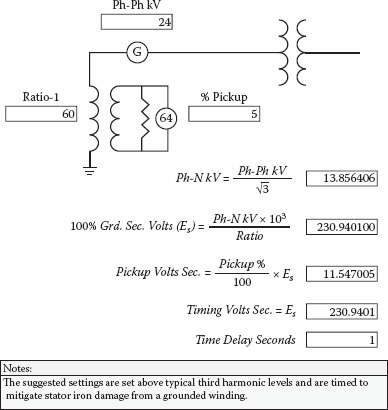
FIGURE 4.41
Stator Ground Relay Settings
Figure 4.41 provides suggested settings for the stator ground overvoltage tripping relay. A default minimum trip or pickup level of 5% of the 100% ground voltage is suggested, with a time delay of 1.0 second for a 100% ground fault. The pickup level should be higher than typical third harmonic voltage levels, to mitigate the possibility of nuisance tripping, and the timing is intended to mitigate the possibility of iron damage from low current prolonged ground fault conditions. Although most stator ground relays are desensitized to third harmonic voltages, many will still operate if the 180 Hz magnitudes are high enough. Additionally, there would also be concern over nuisance tripping if the harmonic filter degraded over time.
For designs that have generator breakers (between the generator and the step-up transformer), a second bus ground detector scheme will need to be installed after the generator breaker to provide ground detection and transient voltage mitigation from arcing grounds when the generator breaker is open. Because of the inability to coordinate the two ground detectors and the possibility of neutral instability or blown fuse problems with grounded wye–broken delta ground detector schemes, it may be advantageous that the second ground detector alarm only for ground conditions. If the generator stator ground scheme trips the unit off-line and the bus ground detector alarm does not clear, then the ground will be in or beyond the generator breaker; otherwise, it will be in the generator or generator side of the breaker. Because the grounded wye–broken delta scheme provides a zero sequence path, it will also detect the third harmonic voltage when the unit is on-line.
Although there is concern with transient torques that can damage the turbine/generator/step-up transformer, out-of-step protection is primarily applied to protect turbine/generators from loss of synchronization or out-of-step slip frequency pulsating torques that can mechanically excite the natural frequencies of rotating systems. Each subsequent cycle can raise the shaft natural frequency torsional levels higher, eventually resulting in cycle fatigue failures if allowed to continue. Slip frequencies for out-of-step events are usually in the range of 0.5 to 5 cycles per second.
When an electrical short circuit occurs on the electrical system, a generator’s watt load is displaced with vars that feed the fault. This, in effect, unloads the machine, and the turbine speeds up. If the electrical system protection does not clear the fault quickly enough, the generator can lose synchronization (dynamic instability) as the speed and associated phase angle differences increase in magnitude. This condition is aggravated by the opening of line breakers that increase the power transfer impedance. Dynamic instability usually occurs when the power angle differences are 120 degrees or greater. A three-phase fault unloads the machine the most and will have the shortest critical clearing time or time before it loses synchronization with the electrical system and becomes unstable—usually in the range of 6 to 20 cycles. At the other extreme are phase-to-ground faults, which only unload one phase; consequently, the critical clearing times can be 3 times longer in duration than in three-phase events.
Electrical faults will normally move to a specific impedance point and stay there until cleared by automatic protective relaying. An out-of-step condition results in a traveling impedance swing or locus that moves through a supervising mho circle repeatedly until synchronization is restored or the generator is tripped off-line. Figure 4.42 illustrates typical impedance swings; the voltage at the machine terminals determines var flows during the swing and a relatively lower generator voltage will result in leading vars into the machine. The electrical center for a typical utility system is normally in the generator or its associated step-up transformer. The center is the total impedance divided by 2 and occurs when the two systems are 180 degrees out; it appears as a momentary three-phase fault to both the generator and the system.
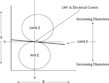
FIGURE 4.42
Out-of-Step Swing Impedance
Figure 4.43 develops the settings for a single blinder scheme, which is simpler to set and more common than other designs. By convention, forward is toward the generator and the reverse reach is toward the electrical system. The suggested forward reach for the offset mho circle is 2 times the generator transient reactance to ensure, with margin, that the generator is covered. The suggested reverse reach is 2 times the step-up transformer impedance to ensure that the transformer and part of the electrical system are covered. For cross-compound units or generators operated in parallel, the reverse reach will need to be modified to account for infeed impedance.
The right and left vertical impedance blinders are set for 120 degrees (extrapolated power angles) or 60 degrees on each side of a perpendicular bisect line of the vector sum of the generator, transformer, and system impedances (electrical center), as illustrated in Figure 4.44. By convention, the generator and step-up transformer are assumed to be purely inductive, and only the impedance angle for the system is considered. The settings are normally determined with a time-consuming graphical procedure, but the figure provides a trig method for calculating blinder settings. In reference to Figure 4.44, the right blinder reaches very far to the left and the left blinder reaches very far to the right. Assuming that the swing is approaching from the right side, the left blinder will already be picked up from load current and will see the event first, followed by the supervising mho circle. As it continues to travel, it will actuate the right blinder, then drop out the left blinder, and finally exit the mho circle on the left side, completing the cycle. Tripping is normally initiated upon exiting the mho circle. If the swing originates from the left side, a reverse sequence will take place, and tripping will occur when the swing exits the supervising mho circle on the right side. Other schemes are available, but the single blinder scheme is one of the simplest as it does not require slip frequency data or concern about the speed of the swing. Because tripping is initiated at the exit of the mho circle when the impedance is higher, the interrupting current levels for generator breakers should be favorable, depending on the breaker tripping time and the slip cycle frequency. Accordingly, tripping time delay is not normally provided unless studies have been performed that indicate that a time delay should be provided to reduce the interrupting current of the generator breaker. This, of course, is dependent on generator breaker tripping time, the electrical system configuration, generator loading, and associated inertia and impedance parameters that influence slip frequencies at the time of the event.
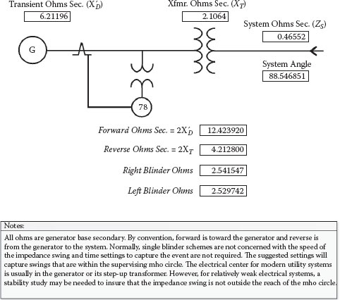
FIGURE 4.43
Out-of-Step Single Blinder Relay Settings
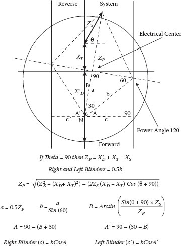
FIGURE 4.44
Out-of-Step Blinder Calculations
Figure 4.45 shows the calculation for determining different reach points for right or left blinders. This is useful for analyzing events and also for testing the out-of-step blinder elements.
As a matter of interest, a similar calculation is shown in Figure 4.46 to determine different reach points for a reactance type impedance element. Reactance elements are sometimes used to cut off mho circles to mitigate overreaching on short transmission lines.
4.4.14 Overfrequency and Underfrequency (81)
Generator overfrequency and underfrequency relays are normally applied to protect turbine blades from resonant frequencies during off-frequency operations. The turbine blade frequency withstand times are cumulative, and damage can occur when the withstand times are used up. The longer low pressure steam turbine blades are normally more sensitive to off-frequency operation. Turbines blades that are under stress (at full load) may resonant at different frequencies than those of unloaded blades, and the unit load at the time may impact the withstand time. On typical utility systems, off-frequency operation events are not numerous and the durations are normally quite short. Although under- and overfrequency resonant limitations are generally mirror images, with the exception of more severe overspeed conditions where centrifugal force becomes the major limitation, the primary concern is really underfrequency, where governor action alone cannot mitigate the occurrence. Underfrequency occurs when the generation does not match the load. If the load is higher than the available generation, the system frequency will decay as the turbines slow down. Utilities normally have underfrequency load shedding programs that will isolate blocks of load in an effort to rebalance available generation with the load demand. Governor action on the generating units will also open steam or fuel valves, but they have limited capability on the amount of additional load that they can pick up. Motors will also slow down; this reduces customer load demand but may also have a reducing impact on generating station output levels. Many generating stations are not equipped with overfrequency and underfrequency tripping and rely on operations to take generating units off-line at 57 Hz if the frequency does not show signs of recovering. By 57 Hz, the utility underfrequency load shedding program has already done what it could to balance load, and other automatic load shedding programs are not typically available to reduce load further. There is also a concern that the generating unit could be isolated with excessive load if other units trip off first, causing significant turbine/generator stationary and rotor torsional forces as the machines are forced to abruptly slow down.
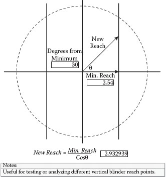
FIGURE 4.45
Vertical Blinder Impedance Points
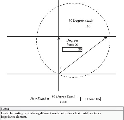
FIGURE 4.46
Horizontal Reactance Supervision
Figure 4.47 provides preliminary settings if information is not available from the turbine manufacturer or the regional transmission authority. The preferred method is to solicit recommendations from the turbine manufacturer, who should have specific knowledge about the frequency limitations of their equipment. The settings provided in Figure 4.47 will allow a single event to consume approximately 50% of the ANSI composite large steam turbine accumulated withstand times before tripping the unit off-line and should coordinate with typical utility underfrequency load shedding programs.
Because potentially damaging events are somewhat rare and normally short in duration, and the underfrequency tripping functions need to coordinate with utility load shedding programs and governor control responses to mitigate unnecessary tripping that can aggravate system disturbances, the suggested time delays are somewhat long in duration. The over- and underfrequency settings are really a compromise between the generating station, the original equipment manufacturer (OEM), and the utility. Turbine manufacturers often take a conservative approach to ensure protection of their equipment and may deny warranty unless the recommended over- and underfrequency tripping is implemented. This can put the generating station in conflict with the utility because the manufacturer’s initial recommendations may not coordinate with the utility underfrequency load shedding program. The utility may not allow the generation company to connect to their system unless the underfrequency tripping coordinates with their program. Sometimes an iterative process takes place before the manufacturer, generating station and the utility can compromise on the over- and underfrequency settings.
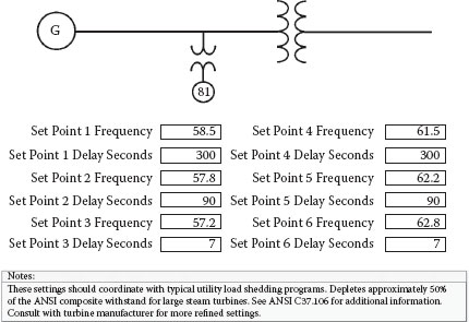
FIGURE 4.47
Overfrequency/Underfrequency Withstands
In more recent years, regional transmission authorities in the United States have recommended settings that manufacturers can use as a guide for their turbine withstands and utilities can use for coordinating their load shedding program.
In 2003, Western Electricity Coordinating Council (WECC), a Western U.S. regional transmission authority, recommended not tripping faster than the following durations at the associated frequencies:
• > 59.4 and < 60.6—continuous
• 59.4 and 60.6—3 minutes
• 58.4 and 61.6—30 seconds
• 57.8—7.5 seconds
• 57.3—45 cycles
• 57 and 61.7—instantaneous trip
Usually generator multifunction digital relays do not provide more than six over- and underfrequency elements. Accordingly, applying the WECC shortest allowable time delays, (assuming they are required to be within the turbine manufacturer’s recommendations), and trying to prioritize the six available set points, the following trip settings are suggested:
• 58.4 Hz—30 seconds
• 57.8 Hz—7.5 seconds
• 57.3 Hz—.75 seconds
• 57.0 Hz—0.1 seconds
• 61.6 Hz—30 seconds
• 66.0 Hz—0.1 seconds
The withstand time for events higher than 58.4 or lower than 61.6 are long enough to rely on operator intervention. A short time delay of 6 cycles is provided at 57 Hz to try and avoid nuisance tripping from spurious events. The last or remaining element is used to back up the mechanical overspeed trips for a steam unit that is normally set for 10% overspeed. A time delay of 0.1 seconds is also provided to mitigate spurious tripping.
The foregoing tripping functions discussed in this chapter drive 86 lockout auxiliary relays that have isolated contacts for tripping and alarming. Several contacts are required to trip the prime mover, excitation system, unit auxiliary transformer, and unit breakers and initiate appropriate annunciation or alarms to guide operations. Tripping should be done in a manner that limits the unit exposure to overspeed, underexcitation, and overexcitation (volts/Hz) and completely isolates the particular failure. The more common practice is to provide at least two 86 lockout relays and split the functions between the relays to provide some form of redundancy, that is, unit differential on one lockout relay and generator differential, transformer sudden pressure, backup zone 1 impedance, and switchyard zone 1 impedance on the other. As mentioned before, the normal unit differential zone of protection for high current short circuit conditions is in between the generator neutral point and the high voltage unit breakers. The relays that are driving the other lockout relay will also detect faults in that zone of protection.
4.4.16 Generator Differential (87)
Almost all generators 10 MVA and larger are equipped with neutral and output side CTs for differential protection. Differential protection in general was covered in Chapter 3. In the case of generators, the relay (secondary side) tripping thresholds at low loads are very sensitive and usually in the 200 to 300 milliamp range to mitigate iron damage. The differential function cannot detect shorted stator turns because the current in equals the current out. As mentioned earlier, this is more of a concern with the slower speed salient pole hydro machines and shorted turns are not that likely with the two and four pole cylindrical rotor machines due to their robust stator coil design. The differential scheme does not normally have the sensitivity to detect ground faults on generators that are high impedance (resistance) grounded. One concern with generator differential is the very high fault current levels, and the installation of CTs with like characteristics is more important to prevent nuisance tripping from through fault conditions. Typical slopes for generator differentials are in the 10% to 25% range.
Baker, Thomas, EE Helper Power Engineering Software Program, Laguna Niguel, CA: Sumatron, Inc., 2002.
General Electric Corporation, ST Generator Seminar, Vols. 1 & 2, Schenectady, NY, 1984.
IEEE Power Engineering Society, IEEE Tutorial on the Protection of Synchronous Generators, Catalog No. 95 TP 102, Piscataway, NJ, 1995.
Klempner, Geoff, and Kerszenbaum, Isidor, Handbook of Large Turbo-Generator Operation and Maintenance, 2nd ed., Piscataway, NJ: IEEE Press, 2008.
Reimert, Donald, Protective Relaying for Power Generation Systems, Boca Raton, FL: CRC Press, 2006.
Westinghouse Electric Corporation, Applied Protective Relaying, Newark, NJ: Silent Sentinels, 1976.
Westinghouse Electric Corporation, Electrical Transmission and Distribution Reference Book, East Pittsburgh, PA, 1964.
Westinghouse Electric Corporation, Total Integrated Protection of Generators, Tutorial, Coral Springs, FL, 1982.