Electrical Maintenance Guidelines
The maintenance guidelines are based on over 40 years of electrical maintenance and engineering experience in generating stations. They represent a procedural effort to improve the availability of generating stations and large industrial facilities and reduce hazards to plant personnel. Some of the text was developed following actual failures in stations and some to try to mitigate equipment failures reported by the industry in general. However, there are a number of areas where the guidelines may need to be revised by a particular generating station to meet their specific requirements. Some of these areas are presented below:
• The guidelines are general in nature and manufacturer’s recommendations for their equipment have precedence over the guidelines.
• There may be government regulatory agencies whose recommendations have priority over the guidelines; for example, the Federal Energy Regulatory Commission (FERC), North American Electric Reliability Corporation (NERC), Occupational Safety and Health Administration (OSHA), National Electrical Code (NEC), and so forth.
• The guidelines assume that electricians, technicians, engineers, and contractors are well trained and qualified to perform the suggested tasks and all appropriate safety measures are taken.
• The station may have unusual environmental conditions that need to be accounted for in the guidelines.
The guidelines represent a good starting document. However, they should be treated as a work in progress that reflects the every changing government regulations, site-specific experience and industry experience in general.
7.1 Generator Electrical Maintenance
The purpose of this guideline is to provide suggested procedures and schedules for the inspection, care, and electrical maintenance of generators.
The guideline is aimed at electrical specialists and does not cover generator support systems that are normally maintained by mechanical crafts, including seal oil systems, seals, bearings, blowers, rotor balancing, water coolers, gas and air cooling systems, leak detectors, and stator inner cooled water systems.
7.1.2 Routine On-Line Slip-Ring Brush-Rigging Inspections
NOTES: The rotor ground fault protection should be taken out of service whenever maintenance is performed on the brush rigging to avoid nuisance alarms or trips and to reduce the voltage reference to ground. Low voltage rubber gloves should be worn prior to contacting any energized conductors. The ground detector should be placed back into service as soon as the brush-rigging work is completed. All activities are to be coordinated with the control room personnel.
Station maintenance should be performed on excitation system brush rigging when:
• Before a unit is returned to service after an electrical fault that results in a unit trip.
• At least once per week on in-service and standby units (on turning gear), preferably before the weekend on Friday.
NOTE: Information should be recorded about the condition of the brushes and brush holders and general visual findings during the inspection. An equipment-specific form should be prepared for each machine that accommodates the number of brushes and other design details. The as-found information should be entered while performing the inspection steps delineated below.
The following checks should be performed during the inspection process:
• Check brush leads (pigtails) for looseness, heating (discolored leads), and frayed wires.
• Check for proper and uniform brush tension. (Once a month, a spring tension scale should be used to spot-check and verify recommended tension).
• Check for brush wear. Brushes should be replaced when 75% of their useful life has been expended. If spring tension becomes less than recommended and the springs are in good condition, the brushes may have to be replaced earlier.
• In general, no more than 20% of the brushes on a polarity should be replaced at one time with the unit in-service. Ample time should be allowed for the new brushes to seat properly before replacing additional brushes. Under no circumstances should brushes of different grades or manufacturers be mixed on the same polarity. If special jigs for bedding the brushes are available at the site, up to 50% of brushes can be replaced at one time, if properly bedded.
• Lift each brush approximately one-quarter inch and gently allow it to return to the operating position under normal spring pressure. Remove brushes showing a tendency to stick or bind and correct the cause.
• Pull out a single brush from each polarity and observe the face for etching and excess powdering.
• Feel the top of each brush and check for running smoothness.
• Check for sparking or arcing.
• Inspect brushes for mechanical wear, cracks, and hammerhead or anvil.
• Inspect integrity of springs and clips.
• Using dry air (not to exceed 35 psi), remove accumulated carbon dust from the brush rigging. A filter mask should be worn during this process to mitigate inhalation of carbon fibers.
• Spot-check 10% of the brushes on each polarity with a direct current (DC) clamp-on ammeter for uniformity in current loading.
• The appearance of rings should be clean, smooth, and highly polished. A dark color does not necessarily indicate a problem. Look for streaking, threading, grooving, and a poor film. Collector ring-polishing or brush-seating procedures may be accomplished by using canvas or brush seating stones when necessary. A stroboscope will go a long way in aiding the visual inspection of the collector rings with the unit in operation.
NOTE: Grinding of collector rings to remove metal should not be performed on on-line energized units (excitation applied to the field) by plant personnel. However, contractors with a proven record, using specially designed stones and a vacuum system to remove the particulate and following proper procedures, have been successfully used to grind the collector rings on-line.
• Check the brush compartment for cleanliness, loose parts, contamination by oil or dirt, or other conditions that may suggest a source of trouble. If an air filter is installed, check for cleanliness of the filter and proper seating of the filter, and change or clean if necessary.
• Problems found during the foregoing inspection steps should be corrected to the extent possible with the unit in-service. Needed maintenance or repairs requiring a unit outage should be identified on a maintenance order.
7.1.3 Inspection of Rotor Grounding Brushes and Bearing Insulation
If accessible with the machine on-line, at the same time the excitation brush rigging is inspected, the condition of the turbine rotor grounding brushes or braids should be checked. The integrity of the grounding elements is essential for minimizing shaft-voltages and shaft or bearing currents.
On some designs with pedestal bearings and sandwich-insulation construction, it is possible to measure the insulation resistance with the unit on-line. When possible, this insulation should be tested for proper values during the inspection. According to the literature, it should fall between 100 kΩ and 10 MΩ or greater.
In some pedestal-bearing arrangements, it is possible to assess the integrity of the insulation by measuring the voltage across the bearing insulation with a high-impedance voltmeter. If the grounding brush is lifted during the test, the shaft voltage is impressed on the bearing insulation. Therefore, if the reading is zero, the integrity of the insulation is compromised. Experience will show what voltage magnitudes to expect for a particular machine. It is not uncommon that shaft voltages are as high as 120 volts.
NOTE: On some designs, the bearing insulation can only be measured during the assembly of the mechanical components. Accordingly, it is important that the measurements be completed at the appropriate time or reassembly sequence. Refer to the original equipment manufacturer (OEM) for specific recommendations for the testing of the bearing insulation.
The following maintenance is recommended during unit outages:
• Brushes should be lifted on generator collector rings whenever units are off turning gear in excess of 24 hours to 1-week duration to mitigate brush imprinting (depending on the local environmental conditions and the plant’s experience). Experience has shown that brush imprinting may result in ring polishing or grinding requirements that shorten the life of the rings.
• Inspect the rings for condition and protect them from the elements to prevent physical damage and oxidization when applicable. A PVC (polyvinyl chloride) film and corrugated cardboard overwrap can provide a protective cover.
• At the beginning of each shutdown and weekly thereafter, test for hydrogen leaks (if applicable) around the collector rings and outboard radial terminal studs.
During routine shutdowns, or at approximately 3-month intervals, accomplish the following maintenance:
• Thoroughly clean the brush rigging and slip rings.
• Check all brush faces and change any brushes that are less than one-third the original length. If more than 20% of the brushes require replacement, they must be seated.
• Thoroughly check the brush rigging for loose parts.
• Check the brush holder to collector ring clearance, which should be uniform and within the manufacturer’s tolerances (typical value is 3/16 of an inch from brush-holder to ring). Brushes should not be allowed to ride closer than 1/8 inch from the edge of the collector rings, and the average centerline of the brushes in the axial direction should coincide with the centerline of the ring when the machine is at operating temperature.
• The cooling grooves for generator collector rings should be inspected for proper depth. If carbon dust is found in the grooves (oftentimes it combines with oil vapor escaping through adjacent bearing seals to form a hard compound), carefully remove to reinstate the cooling capability of the grooves.
• With the unit off turning gear and the brushes lifted, and after completing a thorough cleaning of the insulating material beneath the collector rings, megger the field and perform a DC resistance and alternating current (AC) impedance test of the field winding. The resistance measurements should be corrected to ambient temperature and compared to previous data by an experienced person. Impedance and resistance changes caused by rotor shorted turn and connection problems may be slight.
Generators are usually refurbished whenever their respective turbines high pressure or low pressure (HP or LP) are overhauled. The following maintenance is recommended during major overhaul outages:
• Normally, experienced personnel, contractors, or both, will remove the generator rotor from the bore to facilitate thorough stator and rotor inspections. Care must be taken to mitigate moisture and contaminant intrusion of both the rotor and stator during the outage. It is customary to enclose the removed rotor in a canvas tent and provide canvas flaps that cover the bore openings at each end of the machine for environmental protection. Additionally, where temperature and humidity could be a problem, heated dry air should be blown through the stator bore and the temporary rotor enclosure to maintain these components in a dry condition. Alternatively, recirculating dehumidifiers could be used for long maintenance periods.
• The rotor and stator inspections should be completed by engineers or specialists with prior experience in inspecting generators.
• The outside diameter (OD) surfaces of 18–5 retaining rings should be nondestructive examination (NDE) tested for stress corrosion pitting and cracking during major overhauls. When there is evidence of abnormal moisture intrusion or moisture-induced pitting on the OD of 18–5 rings, they should be removed to facilitate NDE inspections of the inside surfaces. The OD of 18–18 retaining rings should also be NDE tested during major overhauls. If any abnormal cracking or anomalies are found on the OD surface areas, the ring(s) should be removed and NDE testing of the inside surfaces performed. Recently, 18–18 rings have been found to be susceptible to stress corrosion cracking when contaminated with chlorides. Thus, they need to be kept away from such contamination and cannot be assumed to be free of stress corrosion–induced cracking.
• Generators with 18–5 retaining rings should be equipped with continuous dew point monitoring systems and alarms during overhauls to ensure that moisture intrusion problems are quickly identified, recorded, and mitigated.
• The generator rotor bore at the excitation end of hydrogen-cooled machines should be pressure tested with clean dry air or an approved inert gas at 125% of rated hydrogen pressure during overhauls. The pressure is normally applied to the bore plug opening. The bore should be able to hold capped (isolated from air/gas supply) pressure for 2 hours without an indication of a leak. Older machines may be equipped with hydrogen seals on the in-board radial conductor studs only, and the collector ring area or outboard radial studs will need to be sealed off with a can or other means to facilitate the pressure testing. It is prudent to stress-check the integrity of the rotor bore plug itself, which, in some cases, have been found deficient. This plug often is forgotten during inspections, but it has the potential for hydrogen leaks, so it should be inspected, and replaced if necessary, during major overhauls.
• All generator monitoring instrumentation should be calibrated during overhauls and functionally tested at 2- to 3-year intervals in between overhauls.
• Brushless excitation system diodes and associated fuses should be thoroughly cleaned and inspected during overhauls and at 2- to 3-year intervals in between overhauls. Diodes and fuses requiring replacement should be replaced with identical manufacturer’s models and weight measured before and during replacement to ensure that rotor balance is not affected. Where identical diodes or fuses cannot be supplied, the complete set should be replaced with a new matching set.
• Electric insulation tests would normally be performed on stator and rotor windings at the beginning of the outage, when the unit is still assembled and warm (under hydrogen pressure when applicable). This will allow more time to complete any required repairs during the outage window and ensure that the machine is in a dry condition for the testing.
• When applicable, generator heaters should be left switched-on to avoid moisture ingress. The space heaters must be switched off whenever personnel are performing inspections or work in the interior stator areas.
• If applicable, lead-box drain-lines should be inspected for blockage and cleaned if necessary. Liquid level-detection systems should be checked for proper alarms and site glasses cleaned.
Shorted turns in generator two and four pole cylindrical rotor field windings can contribute to vibration problems due to rotor thermal bending from uneven heating associated with nonsymmetrical DC current flow and watt losses in the field windings. Shorted turns can also cause unbalanced magnetic flux in the air gap that can aggravate vibration problems.
Since vibration signature analyses for generator rotor shorted turn problems is not always an exact science, it is desirable to have confirming data from other testing before proceeding with very costly disassemblies and repairs of large machines. Additional tests for confirming the existence of shorted turns in generator rotor field windings are commonly performed before committing to expensive repairs. At this time, the following three test procedures are generally used in the industry to help verify whether or not generator field windings have shorted turns:
• Thermal Stability Testing—Involves changing generator-operating parameters (watts, vars, and cooling) and recording and analyzing the impact on rotor vibration signatures.
• Flux Probe Analysis—Utilizes an installed air gap probe to measure and analyze the magnetic flux from each rotor slot as it passes by the location of the sensor. Some generators are permanently equipped with flux probes and many are not. Installing the probe normally requires a unit outage, especially with hydrogen-cooled machines.
• RSO (Repetitive Surge Oscilloscope) Testing—Involves applying a succession of step-shaped low voltage pulses that are applied simultaneously to each end of the field winding. The resulting reflected waveforms can be viewed on dual channel analog or digital scope screens as two separate waveforms, or after one of them is inverted, and both summed as a single trace. If no discontinuities are present in the winding (due to grounds or shorted-turns), both traces will be nearly identical and if inverted and summed, a single trace will be displayed as a horizontal straight line. Any significant discontinuity arising from a shorted turn will be shown as an irregularity or anomaly on the summed trace.
It should be noted that the foregoing testing (vibration analysis, thermal stability, flux probe analyses, and RSO testing) by themselves do not provide absolute certainty that there is a shorted turn problem in the generator rotor. However, when confirmed by other testing, the probability of the field winding being the cause of the vibration problem increases significantly. Shorted turn anomalies can be masked if they are near the center of the winding or otherwise balanced, if there are multiple shorted turns, if they are intermittent due to centrifugal force or thermal expansion and contraction, if there are grounds, and if there are other contributors to the overall machine vibration levels.
RSO testing has some advantages over other testing in that it can be used periodically during rewinds to verify that windings are free of shorts, on both at rest and spinning de-energized rotor windings.
7.2 Transformer Electrical Maintenance
The purpose of this guideline is to provide suggested procedures and schedules for the inspection, care, and maintenance of oil-filled and dry-type power transformers 500 kVA and larger, including on-site spare units.
The systems and components identified below should be inspected by maintenance personnel on in-service and spare transformers at 2- to 3-year intervals, or at intervals specified by the manufacturer, if they happen to be shorter than 2 years.
• Check heat exchangers and associated components for oil leaks, rust, exterior paint condition, cleanliness of airway passages, and deterioration of cooling fins.
• Check main and conservator oil tanks for oil leaks; correct level, rust, and exterior paint condition. Ensure sight glasses are clean and oil levels are clearly visible.
• Control cabinets should be cleaned, wiring checked for tightness, and motor contactor contacts inspected, cleaned, and dressed as required. Fan and pump loads should be meggered and started to prove proper fan rotation and operation of oil flow indicators. Molded-case circuit breakers should be exercised several times to prevent frozen mechanisms. Motor load current and phase balance should be checked with a clamp-on ammeter. Heaters in the control panel should be checked for proper operation. Care should be taken not to enable trip functions during this inspection.
• Each transformer alarm should be functionally tested to prove proper operation. Care should be taken not to activate a trip function during the alarm testing.
• Check high and low voltage bushings and insulators for physical condition and cleanliness of porcelain or coatings. Check bushing oil level, where applicable, and leaking flanges. If the inspection identifies the need of adding oil during the next outage, care should be taken to use new clean, dry oil of identical or equivalent characteristics.
• Where applicable, verify that a positive nitrogen pressure blanket is maintained within the limits specified by the manufacturer. Typically, low-pressure alarms are set for 0.5 psi, and normal operating pressure is around 2.0 psi.
• Perform a thermograph test of transformer and associated external electrical connections. The test should be performed when the transformer’s load is greater than 25% of full load and has been over that value for at least 1 hour. Prior to the thermography testing of the cooling system, make sure all cooling pumps and fans are running for at least 1 hour (this may require switching the cooling system to manual operation).
• Transformer oil leaks should be cleaned during the inspection and mitigated to the extent possible by re-torquing bolts, tightening valve packing, applying epoxy or sealants, and by gasketing leaking bolts. Care should be taken to select sealants that do not adversely affect the transformer’s oil by reacting with it or contaminating it.
• Desiccant breathers should be inspected and refurbished as required.
Required corrections that can be performed with the transformer in-service should be accomplished during the inspection. Maintenance or repairs requiring a transformer outage should be identified on a maintenance order.
The following tests should be performed on unit related transformers during major turbine overhauls (HP turbine for cross-compound units): Testing of transformers that serve more than one unit should be performed during major turbine overhauls of the lowest number unit. The following tests should also be performed whenever new or spare transformers are placed into service:
• Power factor test (Doble) all unit transformer windings, including bushings and lightning arrestors (except transformers with secondaries rated less than 2.4 kV).
• Resistance test all high voltage (HV) and low voltage (LV) side windings (include all tap positions to check for pyrolitic-carbon buildup on the tap changer contact surfaces).
• Test insulation (megger) of each winding to ground and between windings.
• Test winding turns-ratio(s), polarity, and excitation current (except transformers with secondaries rated less than 2.4 kV).
• Test winding impedance (except transformers with secondaries rated less than 2.4 kV).
• Test and calibrate all transformer monitoring instrumentation.
NOTES: The preceding tests, for the most part, require the transformer be disconnected from external conductors and buses. Before reconnecting, care should be taken to inspect condition of mating surfaces (clean and re-silver where required); use proper contact anti-oxidation grease; torque bolts to the proper value for the particular softer mating surface material; verify that proper joint connection is achieved. Particular care should be taken to prevent oxidization when terminating aluminum connections. Normally, after cleaning, de-oxide grease is applied and then file-carded to dislodge any oxides that might have formed.
7.2.4 Avoiding Pyrolitic Growth in Tap Changers
Pyrolitic growth is the phenomenon by which oil breaks down to an amorphous hard carbon deposit through the effects of the high electric field strength around contact blocks. Once started, it grows along the contours of the field. This growth can force the contacts apart, causing a high contact resistance that can lead to gassing and failure. To mitigate this phenomenon, the following maintenance activities are recommended:
• No-load tap changers: At least once every 2 years, or more often where experience indicates that it is necessary. No-load and off-circuit tap changers should be operated through the entire range of taps, no less than six times. The transformer should be de-energized during this operation. Care must be taken to return the tap to the proper operational position.
• Load tap changers: If possible, once a month or whenever an outage allows it, load tap changers should be operated through the entire range of taps. The transformer can be energized, but preferably with the low voltage breaker open to ensure that secondary system voltages do not become too high or low.
Internal inspections are normally only performed when it is absolutely necessary to drain the oil to perform a maintenance repair. The inspection should be completed by an engineers or specialists with prior experience in inspecting transformers.
• Conduct internal inspection of transformer for abnormal conditions or deterioration of windings, core, core-bolt tightness, insulation, blocking (winding clamping mechanisms), shields, connections, leads, bushings, and tap changer (as required). Look for arcing, carbon tracking, burning, or excessive heating decoloration and debris in tank. Perform a core ground test, where feasible. Micro-ohm (ductor) suspected bolted joints.
• Keep exposure of core and windings to air to a minimum. When core/windings are to be exposed to air for a significant time, that is, overnight, then an external dry air or dry nitrogen source should be connected to ensure positive pressure in the tank.
NOTE: Care must be taken not to damage continuous dissolved gas analysis (DGA) monitoring systems, during draining and refilling of transformers (in particular the application of vacuum). Follow manufacturer’s instructions to prevent damage to the DGA equipment during the foregoing maintenance/inspection operations.
Vacuum-dry out and oil-fill (with de-gasified/filtered oil) should be performed based on manufacturer’s recommendations, test data, parametric data, and/or as indicated by the internal condition of the transformer. After dry-out of the core and windings, the transformer should be filled with de-gasified oil, followed with a tail vacuum and running of the oil-circulating pumps to remove trapped air from the pumps and core/coil assembly. Vacuum should be broken with nitrogen. These activities should only be performed by qualified personnel.
7.2.6 Electrostatic Voltage Transfer
Electrostatic voltage transfer is the phenomenon by which a charge develops between the oil and the insulation systems of a transformer, when the transformer is de-energized and oil is circulated by the oil pumps.
• Running oil pumps on de-energized transformers should be limited to 10 minutes. This is to prevent failure of transformers from electrostatic charging and subsequent tracking of the insulation systems. If additional operation of the pumps is required, a minimum of 2 hours wait should be followed.
• Oil settling before energization—oil should be allowed to settle for at least 18 hours after completing the filling process, before energization of the transformer is attempted.
7.2.7 Dissolved Gas Analysis (DGA)
When performed timely and properly, DGA of transformer mineral oil can provide an advance warning about a deteriorating condition in a transformer before a catastrophic failure occurs. DGA can indicate the present condition of a transformer by analyzing the gas contents. A long-term assessment of a transformer can be obtained by trending the results of DGA on a specific unit. Samples should be taken annually and sent to an experienced lab for analysis. In addition to DGA, the sample should be tested for dielectric quality, moisture content, and aging parameters.
The following gases are normally analyzed for DGA purposes:
• Hydrogen H2—(<101 PPM)—Possible corona
• Carbon Dioxide CO2—(<121 PPM)—Possible decomposition of cellulose
• Ethylene (C2H4)—(<51 PPM)—Possible low energy spark or local overheating
• Ethane (C2H6)—(<66 PPM)—Possible low energy spark or local overheating
• Acetylene (C2H2)—(<36 PPM)—Possible arcing
• Methane (CH4)—(<2500 PPM)—Possible low energy spark or local overheating
• Carbon Monoxide (CO)—(<351 PPM)—Possible decomposition of cellulose
The foregoing parts per million (PPM) levels are suggested for alarm limit purposes. Transformers that have gas concentrations at or higher than the alarm thresholds should be subjected to further tests and investigations and, at a minimum, DGA tested at shorter intervals for trending purposes and assessment of developing problems. See IEEE Standard C57.104 for additional information.
7.2.8 Dielectric Breakdown Test
A dielectric breakdown test of the oil should be completed during the DGA analysis. The dielectric breakdown indicates the capacity of the oil to resist electric voltage. Its capability depends mainly on the presence of physical contaminants, that is, undissolved water, fibers, and so on. The test is normally performed with a 0.040 gap per ASTM D-1816 and the breakdown values should not be less than the following:
• Apparatus <69 kV |
20 kV minimum |
• Apparatus 69–288 kV |
24 kV minimum |
• Apparatus >288 kV |
28 kV minimum |
Each generating station should establish appropriate intervals for washing, cleaning, or greasing or coating transformer and neutral-reactor bushings, arrestors, and insulators based on the environmental conditions present at the particular location.
Locations in a mildly contaminating area will most likely be able to pressure wash with nonconductive water at established intervals based on experience at the particular location. Hot or energized washing in general is not recommended for substations, transformers, and their associated dead-end structures because of the flushing of contamination onto lower level bushings and insulators that can cause power arcs and electrical failures.
Silicone greases are suggested for high contamination areas (plants close to the ocean or high industrial contamination areas). It is expected that most high contamination locations will need to grease insulators at 2-year intervals. White dry bands will form on the insulators and bushings when the grease is near the end of its useful life. At the first indication of white banding, arrangements should be made to remove and apply new grease to the porcelain surfaces. The grease should be applied at a minimum thickness of 1/8 inch to prevent premature white banding. Longer duration RTV materials are also available. These materials are applied once and should last for 3 to 10 years or longer. At the end of the material’s useful life, it requires scrubbing or hydro/blasting for removal before another coat can be applied.
Spare transformer bushings should be stored in either a vertical position or in a horizontal position with the top end at least 18 inches (46 cm) higher than the bottom end. In either of these positions, the insulation structure of the bushing remains under oil.
Transformer gas or oil sudden-pressure relays must have their trips disabled whenever work is to be performed that may affect the internal transformer’s pressure, including adding nitrogen gas, adjusting gas regulator, or work that permits gas venting to the atmosphere. This should be coordinated with the control room to ensure that the relay is returned to service correctly after the maintenance work is completed.
7.2.11 Spare Transformer Maintenance
Nitrogen-blanketed spare transformers should be kept fully assembled with nitrogen pressure maintained above the oil level. CT terminals not used (including hot-spot temperature detectors) are to be short circuited and transformer-bushing terminals should be protected from the weather to prevent corrosion. Paint should be maintained on the external surfaces to prevent corrosion. For spare transformers, oil samples should be taken every 2 years for the purpose of checking for water content and dielectric quality.
Control cabinet heaters should be temporarily wired and energized to keep control cabinets dry. Temporary power to cooling circuits is also advantageous to allow momentary periodic cycling of the cooling system to exercise the fans and pumps.
Whenever a unit main transformer is replaced with a spare or new transformer, a thorough phasing test should be performed before completing the connections to the generator. The transformer should be energized from the switchyard with the generator isolated-phase-bus links open (where applicable). Undisturbed generator bus potential transformers (PTs) or auxiliary system bus PTs, if the auxiliary transformer is also energized, can be used for in-service readings to verify proper rotation, phase angles, and voltage magnitudes.
7.3 Motor Electrical Maintenance
The purpose of this guideline is to provide suggested procedures and schedules for the inspection, care, and maintenance of switchgear-fed induction and synchronous motors (100 HP and larger).
Operation of motor protective relays should not be taken lightly. The following investigation steps should be completed before allowing restarts of motors following protective relay operations.
7.3.2.1 Instantaneous Phase Overcurrent Tripping (50)
Instantaneous phase overcurrent relay minimum trip points should be set well above surge and locked rotor values for the motor. An instantaneous target and corresponding trip indicates that either the electrical protection malfunctioned or was set improperly, or a permanent ground (solidly grounded system only), phase-to-phase, or three-phase electrical fault exists in the cable or motor. Contactor-fed motors are not equipped with instantaneous protection and will blow fuses to clear short circuit conditions. The motor should not be re-energized to avoid overstressing the plant electrical system with a second fault until the cause of the relay operation can be determined and repaired, or reasonable testing to prove the electrical integrity of the motor/cables has been completed. The following investigative steps are recommended:
• Test the electrical protection for proper operation. The instantaneous trip elements are normally set for 250% of nameplate voltage locked rotor amps.
• Physically inspect the outside of the motor, cables, and connections for evidence of electrical failure, that is, odor and smoke damage.
• Perform a 1000-volt megger test of the motor and cables together from the switchgear cubicle and take a polarization index (PI). Measure the three phase-to-phase resistances and the three phase-to-phase impedances.
NOTE: Particular care must be exercised when testing motors from switchgear cubicles, especially when the bus stabs or primary disconnects are energized.
If the foregoing testing does not indicate a problem, motors and associated cables rated 2 kV and higher should be overvoltage or hi-pot tested at the recommended routine value for motors.
If an electrical failure is found, perform a routine inspection of the associated circuit breaker. Also, the motor should be isolated from the cables to determine if the failure is in the motor or in the cables. Motors with a neutral connection brought up to the terminal box should have the neutral opened to allow each phase to be tested separately.
After the foregoing investigative steps are completed and no cause for the relay operation can be found, attempt one restart of the motor. If successful, the motor can be returned to normal service. If unsuccessful, repeat the foregoing steps and install a portable fault recorder to monitor the electrical parameters before attempting another start of the motor.
7.3.2.2 Time Phase Overcurrent Tripping (51)
Time overcurrent targets and corresponding trips are usually caused by mechanical problems in the motor or driven equipment, malfunctioning or improperly set protective relays, control anomalies, or loss of one phase of the supply.
If the motor trips on time overcurrent during starting (rotor thermally stressed), then perform the following:
• Verify that the motor was properly unloaded during the starting cycle.
• Visually inspect bearings and lubricating systems for both the motor and the driven equipment.
• Rotate the motor and driven equipment (where practical) to verify mechanical freedom.
If no mechanical cause for the relay operation can be determined, complete the following electrical tests:
• Test the electrical protection for proper operation. Normally, the relays are timed for 5 seconds longer than a normal starting time at nameplate voltage locked rotor amps.
• Perform a 1000-volt megger test of the motor and cables together from the switchgear cubicle. Measure the three phase-to-phase resistances and the three phase-to-phase impedances.
If the reason for the trip cannot be determined after completing the foregoing steps and allowing for a minimum 1-hour cooling period; restart the motor for test with an operations or maintenance person at a safe distance to witness rotational capability.
If the motor trips on time overcurrent while running (stator thermally stressed), and no problems with the driven load or control system are identified, then do the following:
• Test electrical protection for proper operation. Normally, conventional overcurrent relays are set for 125% to 140% of full load amps.
• Test control system for proper operation.
• Perform a 1000-volt megger test of the motor and cables together from the switchgear cubicle. Measure the three phase-to-phase resistances and the three phase-to-phase impedances.
• Review bearing temperatures (where possible).
• Visually inspect the motor, cable connections, and driven equipment.
If no cause for the relay operation can be found after completing the foregoing items and allowing for a minimum 1-hour cooling period, restart the motor for test after ascertaining a three-phase supply is present at the motor’s source (no blown fuses), and closely monitor the running amperes.
7.3.2.3 Feeder Ground Tripping (51G)
Feeder ground targets and corresponding tripping should not occur unless there is a protective relay malfunction, or permanent cable or motor insulation single phase-to-ground failure. The motor should not be re-energized until the cause of the failure can be determined and repaired, or reasonable testing to prove electrical insulation integrity has been completed. The following investigative steps are recommended:
• Test the electrical protection for proper operation.
NOTES: Limited current residual ground schemes (around 1000 amps for 100% ground fault) are sensitive to current transformer (CT) saturation, connection, and shorted turn problems. Accordingly, the CTs and associated circuitry should be resistance and saturation tested to prove circuit integrity. To avoid false residual ground tripping from momentary CT saturation during starting conditions, instantaneous tripping is usually disabled and the relays are normally timed to operate in around 0.3 seconds for a 100% ground condition.
NOTE: Designs using a single CT that wraps around all three phases (zero sequence CT) are not prone to false tripping from saturation and other CT unbalance problems, and testing of the CT is not required.
• Physically inspect the outside of the motor, cables, and connections for evidence of electrical failure, that is, odor and smoke damage.
• Perform a 1000-volt megger test of the motor and cables together from the switchgear cubicle and take a PI. Measure the three phase-to-phase resistances and the three phase-to-phase impedances.
If the foregoing testing does not indicate a problem, motors and associated cables rated 2 kV and higher should be overvoltage or hi-pot tested at the recommended routine value before re-energization.
If no cause for the relay operation can be found after completing the foregoing steps, attempt a restart of the motor. If successful, the motor should be returned to normal service.
The following testing is recommended when motor feeder circuit breakers are removed from their respective cubicles during circuit breaker and bus routine maintenance:
• Perform a 1000-volt megger test from the switchgear cubicle to determine the health of the motor/cable insulation systems (if surge capacitors and/or arrestors are installed, they can be left connected during the megger test). The minimum megohms for this test is 3 megohms per φ-φ kV; for example, a 4 kV motor should have at least 12 megohms, and a 460-volt motor should have at least 1.4 megohms to ground. Three (3) megohms per kV roughly translates to the IEEE recommendation (1 megohm per kV plus 1 megohm at 40° C) at typical ambient temperatures.
• Perform three phase-to-phase resistance tests to determine the condition of the electrical connections (should be within 5% of each other). A poor electrical connection can cause unbalanced voltages and shorten the available life of the motor. Motors need to be de-rated for voltage unbalances as small as 1%.
• Perform three phase-to-phase impedance tests to ascertain the health of the stator winding and rotor bars (should be within 10% of each other).
In addition to the foregoing testing, during major turbine overhauls (HP for cross-compound units), motors rated 2 kV and higher and associated cables should be overvoltage (hi-pot) tested to predict a future life of the insulation system.
NOTE: If a rewind is required, it is recommended that the new winding be manufactured to Class H insulation to improve life expectancy. In coal-fired plants where fly ash abrasion of insulation is a problem, an RTV-like substance can be applied to the end winding surfaces, helping to reduce fly ash abrasion failures. RTV coating of end windings can also be used to mitigate salt contamination and tracking in open-ventilation medium-voltage motors in close proximity to coastal areas.
Where the failure of a motor would result in the loss or restriction of generation, the motor should be thoroughly inspected internally and frequently enough to ensure continuous service. At least one motor in each group of motors (boiler feed pump, circulating water pump, induced draft fan, forced draft fan, condensate pump, etc.) should be inspected during major turbine overhauls. When a motor is found to be in poor condition, all other similar motors in the group should be inspected.
A major inspection of a motor should include the following checks:
• Remove the upper end bells and internal dust shields and inspect the stator and rotor as far as practical. Verify that the iron-core ventilation passages are clear of contamination (particularly important in coal-fired plants).
• Check the air gap using a feeler gauge (in four positions, if possible). Maximum allowable eccentricity in both the horizontal and vertical direction is 10%.
% Eccentricity = 200(R1−R2)/(R1+R2)
R1 = largest air gap distance and R2 = smallest air gap distance
• Inspect rotor bars and fan blades for cracks, if practical.
• Check the stator end turn areas for proper blocking and support. Undesirable end turn movement can cause black greasing if oil is in the environment or yellow dusting in a dry condition.
• Check for filler strip and wedge migration.
• Inspect the motor connection box for anomalies. Pay particular attention to the condition of the pigtail leads.
• Check the bearings for wear and replace the oil.
• Check and clean or replace the air or water cooler filters.
• Check coupling alignment. Laser alignment systems have proven to be excellent for verifying motor/coupling alignment.
• Inspect heaters and heater wiring.
When the inspection reveals excessive contamination, deterioration, movement or fouling of the windings, the motor should be disconnected and sent out for cleaning and refurbishment.
Anytime medium voltage motors (2 kV and higher) with shielded cables are disconnected, the single shield ground location should be changed from the switchgear location to the motor connection box. A thorough Electrical Power Research Institute (EPRI) study disclosed that high frequency switching transients during second pole closing can get as high as 5 times voltage, which can stress or fail the turn-to-turn insulation in motor windings. Grounding the cable shield, at the motor end only, reduces switching transients by more than 50%.
Motors rated 2 kV and higher, which are sent out for rewind or cleaning and refurbishment, should be hi-pot tested in the service shop prior to delivery to the station. All motors should be megger, PI, resistance, and impedance tested immediately upon return to the station from a repair facility The megger, PI, resistance, and impedance testing should be repeated from their respective cubicles when the motors are connected to the feeder cables. All test values should be recorded to permit comparison to measurements in the future.
7.3.5 On-Line and Off-Line Routine Inspections
Based on local environmental conditions, a periodic (at least annually) maintenance routine should be established for the following:
• Cleaning or replacement of air filters and connection box desiccant breathers (if applicable).
• Bearing lubrication system maintenance. Follow manufacturer’s recommendations for greasing bearings; overgreasing may cause bearing failure.
• Motor heaters (which are normally energized when the motor is not running) should be equipped with ammeters or LEDs that indicate heater current flow is normal. The heaters and circuitry should be inspected for proper operation during the scheduled routine.
7.3.6 Motor Monitoring and Diagnostics
• Thermographic inspection of leads, frame, and bearings is usually economical for larger motors.
• Motors 1500 HP and larger are normally equipped with embedded resistance temperature devices (RTDs) in their stator windings for monitoring stator temperatures. These devices can be used to drive recorder, DCS systems, and newer digital protective relays. In most plants, they are not being utilized but are always accessible in external connection boxes for measuring stator temperatures if an issue needs to be resolved on the temporary overload capability of the motor where the unit output is limited because of motor loading or to assess the effectiveness of the cooling system or cleanliness of the cooling passages. Generally, the RTDs are slow to respond and not considered effective for severe events, that is, motor stall or locked rotor conditions.
• Current spectrum analysis can be performed routinely for detecting incipient broken rotor bars and/or short-circuiting rings. However, it may be more economical to perform the testing only on motors that exhibit vibration problems or have a history of squirrel-cage rotor problems.
• Either routine or continuous partial discharge monitoring of stator windings is available for motors rated 6 kV and higher. Normally, the cost of these devices can be justified only for motors that are problematic or part of critical plant processes.
7.4 Switchgear Circuit Breaker Maintenance
The purpose of this guideline is to provide suggested procedures and schedules for the inspection, care, and maintenance of switchgear circuit breakers.
Proper maintenance of switchgear circuit breakers is essential to obtaining reliable service and performance. Circuit breaker failures are a potential hazard to personnel and other plant equipment and could result in the loss of generation capability.
NOTE: This guideline does not apply to SF6, oil, and free standing generator or switchyard circuit breakers.
7.4.2 General—Switchgear Circuit Breakers (200 Volts to 15 kV)
Modern switchgear circuit breakers have sensitive mechanisms with critical tolerances and internal forces and loadings that must be maintained in close adjustment to operate properly. Deviation in adjustment could result in improper operation or electrical failure. It is therefore imperative that the manufacturer’s recommended settings and instructions are understood and followed. All personnel associated with maintaining circuit breakers and their associated cubicles should be well acquainted with the manufacturer’s instructions and recommendations pertaining to both the circuit breakers and the cubicles.
NOTE: Particular care must be exercised when working on breakers that rely on stored energy systems (spring, air, or hydraulic), and appropriate safety practices must be followed.
Because the insulating properties of circuit breakers are adversely affected by the presence of moisture and contamination, all possible precautions must be taken to prevent their intrusion. Spare breakers, and other breakers that need to be stored outside of their designated cubicles, should be stored in suitable heater-equipped enclosures to prevent the intrusion of moisture and contamination. For the safety of plant operators who stand in front of circuit breakers during live rack-in operations, it is essential that the breaker insulation systems prevent the occurrence of insulation flashovers and explosions. Switchgear rooms must be maintained in a clean condition. Cubicle doors and access panels must be kept closed to mitigate moisture and contaminant intrusion. Fans and dampers for positive-pressure switchgear rooms should be properly maintained. Ceiling water leaks should be repaired quickly, and water should not be used to hose down areas near switchgear locations.
No work should be attempted on racked-in energized circuit breakers at any time. All testing and adjustments should be performed with the breaker in the fully racked-out or test position. Additionally, no work should be attempted on the control circuits of racked-in circuit breakers for off-line units, where an inadvertent breaker closure would energize an at-rest generator. The foregoing applies to generator circuit breakers and to unit auxiliary transformer low side breakers (backfeed through the auxiliary transformer) on unit designs where generator bus circuit breakers are not provided.
Adjustment of the main contacts and primary disconnects for source and tie breakers is particularly critical. Current flow through feeder breakers is usually well below the continuous rating. However, it is not uncommon for source and tie breakers to carry close to rated current; consequently, they are much more prone to contact and primary disconnect overheating that can lead to ground and short circuit failures.
7.4.3 Inspection and Testing Frequencies
Switchgear circuit breakers and cubicles should be mechanically inspected and electrically tested at the following intervals or events, and/or following manufacturer’s recommendations:
• Periodically, at 2- to 5-year intervals.
• During unit overhauls.
• Before placing new or modified breakers into service.
• Before energizing breakers that have been out of service for over 12 months.
• After an interruption of electrical short circuits, other than a ground fault in a resistance-grounded system.
• After 1000 close-open operations (or less, depending on manufacturer’s recommendations) following the last inspection.
During the mechanical inspection process, the following items should be completed:
• Remove arc-chutes to facilitate the inspection.
• Use vacuum, dry air, or hand wipe to remove dust and other contaminants from the breaker and arc-chutes (do not use air pressure on arc-chutes that contain asbestos).
• Inspect silver-plated parts and replate as required, following manufacturer’s recommendations.
• Inspect, adjust, clean, and replace main and arcing contacts as needed. Ensure the contacts have the proper “wipe,” alignment, and synchronism and are adjusted as specified by the manufacturer.
NOTE: A stamp impression of the contacts can be made using very thin tissue paper to ensure that the contact surfaces “make” evenly.
• Clean disconnect or finger clusters, clean control fingers, check spring pressure, and lubricate lightly with approved grease to enhance proper engagement. Check all associated screws and bolts for tightness.
• Perform an overall inspection, looking for loose wiring and connectors or components, heating, cracked insulation, corrosion, and anomalies. Complete repairs as required.
• Check for tracking and corona activity, in particular in those areas close to the interface between insulated and noninsulated conductors.
• Close the breaker manually a number of times and compare variations in mechanical force needed and audible sounds. Variances should be investigated.
• Check for proper operation and condition of auxiliary contacts and relays.
• Vacuum-breaker bottles can leak. To ascertain proper vacuum integrity, some manufacturers recommend carrying out a “pull test” to measure the vacuum by the force required to pull apart the contacts.
• Lubricate moving parts as recommended by the manufacturer or in accordance with experience with a particular type of breaker.
• Prove that the mechanical trip push-button will trip a closed circuit breaker.
In general, acceptable measurement values for circuit breaker testing will depend on the model and type of circuit breaker. Experience, manufacturer’s information, and review of previous test records will indicate a practical range of acceptable readings for a particular circuit breaker. Corrective action will need to be taken when test measurements are outside of that range. The following electrical testing should be completed to assess the condition of the circuit breaker and to determine if further maintenance is required:
• Before installing the arc-chutes, perform a micro-ohm test of each phase from disconnect stab (or cluster) to disconnect stab (or cluster) with the breaker closed, after manually opening and closing the breaker at least three times. If the breaker is not racked into a test device and is equipped with clusters, the micro-ohm readings should be taken from the mating surfaces that the clusters are installed on and not from the cluster itself. If the readings are acceptable, install the arc-chutes for further testing; otherwise, isolate and correct the problem.
• Perform an overvoltage test of the breaker. All circuit breakers should be tested with a 1000-volt megger. If the megger test results are acceptable, an AC hi-pot (overvoltage) test should be performed on 2 kV and higher voltage-rated breakers. Considering the severe consequence of an insulation breakdown, the low cost for a low capacity 30 kV AC test set, and that breaker insulation failures are easy to repair, the AC hi-pot testing of all medium voltage (2 kV and higher) switchgear circuit breakers is recommended.
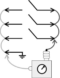
FIGURE 7.1
Open-Pole Insulation Test
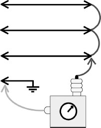
FIGURE 7.2
Phase-to-Ground Insulation Test
FIGURE 7.3
Phase-to-Phase Insulation Test
The following are the routine AC overvoltage test values for switchgear circuit breakers of various voltage ratings:
• 2.4 to 5 kV breakers |
14.25 kV AC |
• 7.2 kV breakers |
19.5 kV AC |
• 13.8 kV breakers |
27.0 kV AC |
The breaker should be able to hold the test voltage for 1 minute.
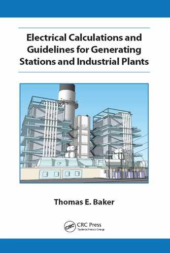
As illustrated in Figures 7.1, 7.2, and 7.3, three tests will be required to properly megger or overvoltage stress the circuit breaker:
• Open-pole insulation
• Phase-to-ground insulation
• Phase-to-phase insulation
The following describes each test:
• Open-pole insulation: With the breaker open and A, B, and C phases jumpered together on both sides of the circuit breaker, connect the “hot” lead to the movable-contact side, and the test set return-lead and breaker frame-ground to the stationary-contact side. Minimum insulation resistance for this test is 3 megohms per rated phase-to-phase kV.
• Phase-to-ground insulation: With the breaker closed and all jumpers and leads removed from the stationary side, connect the return to the breaker frame-ground to test the phase-to-ground insulation. Minimum insulation resistance for this test is 3 megohms per rated phase-to-phase kV.
• Phase-to-phase insulation: With the breaker closed and A and C phases jumpered together, connect the hot lead to B phase and the return and breaker frame-ground to A and C phases to test the phase-to-phase insulation. Minimum insulation resistance for this test is 6 megohms per rated phase-to-phase kV.
Hi-pot leakage currents should be recorded during the foregoing testing and investigated when out of acceptable ranges or when there is a significant unbalance between phases. If the breaker does not pass the open pole megger or hi-pot test, the arc-chutes may require cleaning. Care must be taken when cleaning arc-chutes that contain asbestos, especially if the material is friable. Arc-chutes that do not contain asbestos can normally be glass-bead blasted. Arc interruption by-products can be removed by hand from asbestos containing arc-chutes, with nonmetallic grit sandpaper if care is taken to avoid the asbestos material. Ceramic surfaces can also be wiped clean with an approved solvent.
NOTE: Applicable local regulations must be followed when handling asbestos materials or when performing maintenance activities with equipment containing asbestos or suspected of containing asbestos.
• Vacuum breakers: The normal method for testing vacuum-bottle integrity is to overvoltage or hi-pot the bottles. Manufacturer’s recommendations, intervals, and precautions should be followed. At a minimum, vacuum-bottle hi-pot tests should be performed at no more than 5-year intervals. The tester should be aware of the possibility of x-ray radiation from vacuum bottles under test.
Connect the breaker to a test stand and perform the following tests:
• A 70% of rated-voltage close test: Failure of the breaker to close may indicate the need for mechanism cleaning, lubrication, and adjustment.
• A 50% of rated-voltage trip test: Failure to trip may indicate the need to clean, smooth, lubricate, and adjust the latch mechanism.
• Full-voltage close and open timing tests: Using a high-speed cycle counter, measure the close and open time for three consecutive operations. If the average of the three timing tests falls outside the acceptable range, the bearings may need cleaning, lubrication, or replacement.
• Test the trip-free and safety interlocks for proper operation and correct any deficiencies.
During the cubicle inspection process, the following items should be completed:
• Examine the bottom of the cubicle for parts that may have fallen from the breaker. The bottom of each cubicle should be maintained clean and free of any foreign objects to facilitate the detection of fallen parts.
• Verify that the mechanical safety interlocks and stops are intact.
• Check that the cubicle heaters (where applicable) are functioning properly.
• Verify that the rack-in mechanism is aligned correctly.
• Lubricate racking mechanism (jacking screws and bearings) according to station experience or manufacturer’s recommendations. Check brush length of associated motor (when applicable).
• Perform an overall inspection looking for loose wiring or components and anomalies. Complete repairs as required.
• Verify that the shutter mechanism functions properly.
• The primary disconnects should be inspected for signs of overheating, cracked insulation, cleanliness, and misalignment.
NOTE: Normally, the bus side will be energized; hence, the proper safety measures must be followed.
The following system checks should be completed prior to returning the breaker to service:
• Have the breaker racked into test position, turn the DC on, witness a close-open operation, and verify that the cubicle door status lamps and mechanical semaphores are functioning properly.
• Arrange to have the open breaker racked into operating position and verify proper cell depth and alignment.
• When the foregoing inspection process is satisfactory to the participating electrician or technician, an adhesive label should be attached to the front of the breaker that indicates the date of inspection and the name of the responsible person.
7.4.9 Generator DC Field Breakers
Generator field breakers should be inspected according to the same guidelines as detailed for other switchgear circuit breakers. In addition, particular attention should be given to the mechanical adjustments and condition of the discharge resistor insertion contacts. Ohmic measurements of field breaker discharge resistors should be taken during the inspection process to verify proper values. Considering the importance of generator field breakers, prior to returning racked-out generator field breaker to service, and allowing for possible troubleshooting time, a close-open test should be performed from the control room, with the breaker racked in (without excitation power), to ensure that the breaker is functioning properly.
7.5 Insulation Testing of Electrical Apparatus
The purpose of this guideline is to provide suggested criteria and intervals for the insulation testing of electrical apparatus. This guideline is not intended to be a complete procedure on insulation testing, and personnel performing the tests are expected to be familiar with safety and other detailed aspects of high voltage insulation testing. Testing is performed to verify equipment integrity and to provide a measure of confidence that the insulation will prove reliable until the next major outage.
NOTE: Although some overvoltage test currents are below the accepted lethal levels, the stored charge energy in the insulation capacitance can be lethal. The stored charge must be discharged or drained before the device can be considered dead. The charge is stored by dielectric capacitance between the object under test and the surrounding ground. The rule of thumb is, at minimum, to discharge by connecting low resistance from the conductors of concern and ground and maintain the connection for at least 5 times longer than the overvoltage test duration.
7.5.2 Apparatus 440 Volts and Higher
To determine the integrity of 440 and higher voltage AC apparatus, 1000-volt megger testing should be performed periodically. The frequency of testing should be determined by site-specific environmental conditions and experience with the particular equipment. In general, the maximum interval between tests should not exceed 3 years.
NOTE: For apparatus 4 kV and higher a 2500-volt megger test set can be used, and for apparatus 5 kV and higher a 5000-volt megger can be used. However, experience indicates that for most practical purposes, a 1000-volt instrument provides an accurate enough measurement for apparatus of all voltage ratings.
The following presents a minimum megohm criterion based on operating conditions for all AC electrical apparatus 460 volts and higher that should be met before energizing equipment. The following test criterion assumes the temperature of the apparatus under test is 25°C. This approach will be conservative for measurements carried out at temperatures higher than 25°C.
7.5.3 Normal Routine Maintenance
The minimum megohms for testing all three phases at the same time is 3 megohms per rated φ-φ kV; for example, a 4 kV motor should have at least 12 megohms to ground, and a 460 volt motor should have at least 1.4 megohms to ground. Three (3) megohms per kV roughly translates to the IEEE recommendation for large AC three-phase motors (1 megohm per kV plus 1 megohm at 40°C) at ambient temperatures and, in the interest of simplicity, is suggested for all electrical apparatus.
This criterion assumes that all three phases are being tested simultaneously. When one phase at a time is tested (cables or breakers) with the other two phases grounded, the minimum megohms should be multiplied by 3. For example, an A-phase 4 kV cable should have a least 9 megohms to ground per rated φ-φ kV, or 36 megohms total to ground when tested isolated from the other, grounded, phases.
NOTE: IEEE Standard 43 (Testing Insulation Resistance of Rotating Machinery) indicates that when meggering one phase at a time (with the other two grounded), the measured value should be multiplied by 2, unless guards are used, in which case the readings should be multiplied by 3. This guideline opted for the more conservative approach of multiplying by 3 in both cases.
This criterion also applies to a complete system or parts of a system at the apparatus level. In other words, it is acceptable to isolate apparatus units to meet the requirement individually; that is, a motor can be isolated from the cables, and if the cables and motor meet the requirement separately, they can be reconnected and energized.
Electrical apparatus that do not meet the aforementioned minimum megohm requirements should be cleaned, dried out, or refurbished prior to energizing. On some apparatus, a 10 minute PI test will help to determine if the low readings are due to moisture or other contamination. The PI test divides the 10 minute measurement by the 1 minute measurement. Because the test voltage is DC, the capacitive charging current decreases as the test duration continues, resulting in higher megohm values. In general, a PI value of 2.0 is considered good for most cases unless the apparatus has a history of lower PI values.
7.5.4 Avoiding a Forced Outage or Load Restriction
Some plants are willing to take an economic risk and use a different minimum megohm value to avoid a forced outage of the unit or load restriction of 2 megohms per rated φ-φ kV (with a minimum of 1 megohm regardless of voltage); that is, a 4 kV motor should have at least 8 megohms, and a 440 volt motor should have at least 1 megohm to ground.
This criterion assumes that all three phases are being tested simultaneously. Where one phase at a time is tested (cables or breakers) with the other two phases grounded, the minimum megohms should be multiplied by 3. For example, an A-phase 4 kV cable should have a least 6 megohms to ground per rated φ-φ kV, or 24 megohms total when it is isolated from the other grounded phases.
This criterion also applies to a complete system or parts of a system at the apparatus level. In other words, it is acceptable to isolate apparatus units to meet the requirement individually; that is, a motor can be isolated from the cables, and if the cables and motor meet the requirement separately, they can be reconnected and energized.
Electrical apparatus that do not meet the aforementioned minimum megohm requirements should be cleaned, dried out, or refurbished prior to energizing. On some apparatus, a 10 minute PI test will help to determine if the low readings are due to moisture or other contamination.
7.5.5 DC High Potential Testing
General: Generators and motors 2 kV and higher voltage should be routine overvoltage tested during major turbine overhaul outages (HP turbine for cross-compound units). Normally, for convenience, cables that feed motors are included in the overvoltage test (motor routine values not considered high enough to unduly stress cable insulation). Otherwise, the routine overvoltage testing of cables is not recommended.
It is impossible to tell before testing if the apparatus insulation will fail during the overvoltage (hi-pot) test. Accordingly, time to procure material and repair or replace equipment must be provided when scheduling the test. However, the routine test values provided for motors and generators in this document are the minimum (125% instead of 150%) recommended by IEEE. These values are considered searching enough to provide a measure of confidence that the insulation will not fail before the next major outage and yet do not stress the insulation system enough to force an undesirable premature failure. The higher test values provided for new or refurbished apparatus assumes that the manufacturer or repair agency is financially responsible for a test failure (under warranty) and should not be performed if that is not the case.
A 1000-volt megger polarization test of 2.0 or greater would normally be required before proceeding with a hi-pot test on generator and motor stator windings. The PI (ratio of the 10 minute to the 1 minute insulation resistance readings) is an indication of the fitness of the winding for the overvoltage test. A low PI (less than 2.0) may indicate that cleaning, dry-out or repair is required before the hi-pot can be performed. However, some insulation systems in good condition will not provide a PI of 2.0 or greater. Where that is the case, and the PI measurement is in agreement with historical measurements for the particular insulation system, proceed with the overvoltage testing.
A minimum insulation resistance using a 1000-volt megger of 9 megohms per rated φ-φ kV is required when one phase is tested in isolation from the other phases (preferred for generators and cables) and 3 megohms per rated φ-φ kV when all three phases are tested together (motors). Apparatus with megger readings below minimum should not be hi-pot tested. Apparatus not meeting the recommended minimum megohm values should be dried out, cleaned, or refurbished prior to hi-pot testing.
NOTE: Overvoltage testing should be performed only by technicians or engineers who are familiar with the required safety and test procedures and are properly trained to perform the testing. Due to the high cost of test failures, the overvoltage testing of 10 MVA and higher generators should be witnessed by supervisors or engineers who also have experience in overvoltage testing.
Motors and generators are normally tested at the start of the outage to allow time to complete any required repairs during the outage window. Additionally, it is desirable to perform the testing while the apparatus is in a dry condition (before disassembly or in a cold standby condition). Generators are normally tested completely assembled and under hydrogen pressure (where applicable). On generators equipped with inner water-cooled stator coils, the water is normally evacuated by pulling a vacuum to facilitate megger testing for acceptable PI and minimum insulation resistance values before proceeding with the overvoltage testing.
As illustrated in Figure 7.4, wye-connected generators are normally disconnected at the output and neutral ends. Each end of the winding is connected together with copper bonding wire, and each phase is individually tested to ground with the other two phases grounded. All three phases for motors without neutral leads brought up to the termination box are normally tested simultaneously to ground. Motors and associated cables are usually tested together from the switchgear cubicle with all three phases bonded together, as shown in Figure 7.5. Cables should be separated from the motor only when the readings of the combined motor-cable system are not satisfactory.
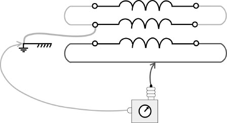
FIGURE 7.4
Generator DC Hi-Pot Test
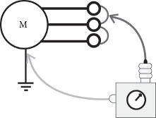
FIGURE 7.5
Motor DC Hi-Pot Test
Generators are normally tested with a rate of voltage rise or steps of approximately 2 kV DC and motors with a rate of rise of approximately 1 kV DC. The operator should record the voltage and current readings (after stabilization) for each step. The DC current should be closely monitored and if the current starts to rise in an uncharacteristic manner, indicating that insulation break down is imminent, the test should be aborted by steadily reducing the voltage to zero. A successful test is concluded when the recommended voltage value is reached and the current is stable for 1 minute. At the conclusion of the test, the voltage should be steadily reduced to zero to avoid sudden changes and the development of potentially damaging transient voltages.
The following calculated test values are based on nameplate rated kV.
7.5.6 Generator and Motor Stator Winding Test Values
• Field acceptance test for new stator winding
2 × rated φ-φ kV + 1 kV × 1.7 × .85 [kV DC]
Examples (13.8 kV generator = 41 kV DC)
(4 kV motor = 13 kV DC)
• First-year test (under warranty)
Rated φ-φ kV × 1.5 × 1.7 [kV DC]
Examples (13.8 kV generator = 35 kV DC)
(4 kV motor = 10 kV DC)
• Routine test
Rated φ-φ kV × 1.25 × 1.7 [kV DC]
Examples (13.8 kV generator = 29 kV DC)
(4 kV motor = 8.5 kV DC)
7.5.7 Generator Rotor Field Test Values
• Field acceptance of new winding insulation
10 × rated voltage × 1.7 × .8 [kV DC]
Example (500 VDC field = 6.8 kV DC)
• First-year test (under warranty)
10 × rated voltage × 1.7 × .6 [kV DC] (if under warranty)
Example (500 VDC field = 5 kV DC)
• Routine test (during overhauls)
One thousand (1000) volt megger test only: acceptable results will be a minimum PI of 2.0 and a minimum insulation resistance of 0.1 × rated voltage in megohms. A 500 VDC field should have a minimum megohms of 50 to meet this requirement. Normally, several hours of cleaning the insulation material beneath the collector rings are required to remove oil and carbon brush contamination before successful readings can be obtained.
• To avoid a forced outage
4 megohms per kV
Example (500 VDC field = 2 megohms)
7.5.8 Generator Neutral Buses or Cables
Generator neutral bus and/or cable to the grounding transformer should be disconnected at each end and routinely hi-pot tested during overhauls at the routine value for the generator stator.
Voltage cables 5 kV and higher should not be routine tested at cable hi-pot values during overhauls unless the integrity of the cable is suspect. Because of high test voltages and the limitations of the switchgear and associated CTs, the cables must be disconnected at both ends to perform a full value routine level hi-pot test.
New cables should be hi-pot or partial discharge tested before and after installation to fix warranty responsibility and to ensure that the cables were not damaged during shipment or installation.
The hi-pot values for cable testing are dependent on the type of insulation material, insulation thickness, and the voltage class. The variations are too numerous to cover in this guideline. Normally, the after installation test is performed at 80% of the factory test value and routine tests are performed at 60% of the factory value. Please refer to the Insulated Cable Engineer Association (ICEA), Association of Edison Illuminating Companies (AEIC), Institute of Electrical and Electronic Engineers (IEEE), Electrical Power Research Institute (EPRI), and other appropriate standards for test values and details before hi-pot testing cables.
Where the cable manufacturer does not recommend hi-pot testing, partial discharge testing should be performed instead. Cable insulation systems are chemically complex and represent many variations or families within the same generic type, that is, CLP and EPR (ethylene propylene rubber). Cable hi-pot values may shorten the life of some cable insulation systems by causing molecular changes and/or voids in the insulation. Motor hi-pot levels are significantly lower than cable hi-pot values and consequently are considered safe for all cable insulation systems.
7.6 Bus and Motor Control Center (MCC) Maintenance
The purpose of this guideline is to provide suggested procedures and schedules for the inspection, care, and electrical maintenance of buses and MCCs. This guideline is intended to include all major electrical buses, that is, generator isolated phase and neutral buses, transformer outdoor buses, auxiliary power switchgear buses, MCC buses, battery distribution buses, and critical control power buses.
Where outages permit, electrical buses should be inspected on 2- to 5-year intervals. Generator and transformer isolated phase buses are normally inspected during unit overhauls.
The buses should be checked for moisture, contamination, overheating, excessive oxidization, discoloration, electrical tracking, flexible shunt or braid erosion, bird nests, rodents, proper sealing, and any other anomalies. The primary disconnects for each position (bus and load side) should be included in the inspection for switchgear buses. Deficiencies should be corrected during the inspection process. Accessible bus insulators should be cleaned and bus bolts checked for tightness. The bolts should be torqued to values that are compatible with the softest material involved and not necessarily to the value recommended for the particular bolt. Flexible braids and shunts that are eroded in a manner that would reduce their current carrying capability should be replaced. Where necessary, silver-mating surfaces should be replated. Aluminum oxide can cause high resistance connections, and treatment with an approved de-oxide grease is necessary to prevent failures of aluminum connections. The oxide can form very rapidly, and the grease should be applied immediately after cleaning. Normally, the mating surface is brushed or file carded after the grease is applied to ensure that any oxide formations that may have formed during the process are broken loose.
The buses should be megger tested during the inspection or overhaul process. The minimum megohms for a single-phase test (one phase at a time) is 9 megohms per rated phase-to-phase kV; that is, each phase of a 4 kV bus should have at least 36 megohms to ground with the other two phases grounded.
In addition to megger testing, switchgear and MCC buses should be micro-ohm tested during the bus inspection to prove the integrity of the associated bus connections and breaker and bucket primary disconnects. This can be accomplished by grounding all three phases at the source and measuring the micro-ohms from the source to each phase in each breaker cubicle or MCC position. The micro-ohms for phases located within the same position or cubicle should be within 5% of each other, and the measurements should increase slightly for positions that are farther from the source.
Additionally, to take advantage of the accessibility (breakers out of the cubicles), the switchgear and loads should be megger, resistance, and impedance tested during the bus inspection and testing.
7.6.4 MCC Position Inspections
At 2- to 5-year intervals, MCC positions should be physically inspected. The MCC positions should be inspected for loose components, contamination, moisture, overheating, and connection tightness. The positions should be cleaned and the main contacts cleaned and dressed as required. Anomalies should be corrected during the inspection process.
NOTE: The MCC position may be energized at the power disconnect device (molded case breaker or fused disconnect). No maintenance should be attempted on the energized portion of the MCC position.
MCC loads should be megger, resistance, and impedance tested during the position inspection process. Additionally, motor operated valves and dampers should be electrically operated through their range (where possible) to ensure proper operation.
The purpose of this guideline is to provide suggested procedures and intervals for the testing of protective relaying. Proper relay operation is essential to mitigate equipment damage and hazards to personnel, and to reduce the duration of forced outages.
Routine tests on protective relays and associated equipment are normally made in accordance with standards, test manuals, and manufacturer’s instructions. Only properly trained engineers/technicians should be allowed to maintain protective relay systems. All testing activities should be coordinated with control room personnel.
7.7.3 Testing Schedule (440 Volts to 765 kV)
Protective relay routine testing is normally performed at 2- to 5-year intervals or plant overhaul outages, but should not exceed 6 years in duration.
When possible, the following steps should be completed during the routine testing:
• Where possible, megger and inspect CTs and PTs and associated wiring. Electronic relays should be isolated during the megger test.
NOTE: Care must be taken to ensure that the CTs under test are completely de-energized. CTs that are wrapped around an energized bus or connection, even though there is no current going through the bus or connection, must be treated as energized.
• Perform a thorough mechanical check of the protective relays, switches, wiring terminals, and auxiliary relays and timers. The inspection should include looking for metal chips or filings, or other foreign objects in the area of the magnetic gaps. Contacts should be cleaned as required. Dirt and contamination should be removed with a soft brush, or by low-pressure dry air or vacuum.
• Complete an electrical calibration of the protective relay (normally with the relay in its case) using in-service taps and adjustments to ensure that it will operate properly (within 5%) over the intended range.
• Prove that the tripping and alarm circuits will perform their intended operations.
NOTE: High and medium voltage circuit breakers, fuel trips, and turbine steam valve operations should be kept to the minimum required during each relay routine and trip test. One trip operation for each apparatus function is required; subsequent tests from different (86) or direct trip relays should be proven by drawing light bulb current on the particular trip wire or open trip cut-out switch instead of actually retripping the equipment.
• Make a final in-service test to determine that the protective group is being supplied the proper currents and potentials as required for the various elements after the relay group is returned to service.
7.7.5 Primary Overall Test of Current Transformers (CTs)
Primary injection tests from each phase and CT group, with all secondary current devices included, should be performed to ensure proper operating values and performance whenever the following conditions are met:
• During the initial installation or replacement of CTs.
• Anytime a CT’s ratio is changed or there is a major wiring change in the secondary circuit.
• If there is any reason to suspect faulty operation of the CTs.
NOTE: Secondary tests (light bulb current) are acceptable for proving minor changes to the secondary wiring and for proving major changes where primary injection tests are not practical because the CTs are not accessible.
Each station should maintain files on the protection philosophies, calculations, relay settings, and coordination of protective relaying for low voltage switchgear-fed loads and higher voltage electrical systems.
Relay data cards should be maintained at the relay. The cards should show the date of the last routine test and the name of the responsible technician or engineer. The card should also indicate the name of the circuit, instrument transformer ratios, and the relay settings in secondary values. Where a separate relay is provided for each phase, the data card should be attached to the A-phase relay only. The relay settings for multifunction digital relays do not need to be shown on the relay card.
7.7.7 Multifunction Digital Relay Concerns
With multifunction digital relays, there are two areas of concern:
• When testing digital relays, there can be element or function interference, and it may be desirable to temporarily take elements or functions out of service to facilitate the testing. In this case, documented procedures should be established; that is, check sum numbers, software comparison routines, and so forth, to ensure that all desired alarming and tripping functions are placed back into service following the testing.
• The relay settings provided should be presented in a manner where the commissioning and routine testing engineer or technician has absolutely no doubt about the intentions of the protection engineer responsible for issuing the settings. The information must be presented in way that is not subject to interpretation.
7.8 Battery Inspection and Maintenance
The purpose of this guideline is to provide suggested procedures and intervals for the maintenance of plant battery banks. Batteries must be maintained correctly to prevent unnecessary outages and to ensure that backup emergency power is available for the turbine emergency DC oil pumps and other important loads. Proper battery maintenance is vital to ensure that control and shutdown systems function properly to mitigate damage to equipment and risk to plant personnel. This guideline covers lead acid batteries in detail; for other types of batteries, follow manufacturer’s recommendations.
Approved maintenance and safety procedures should be in place before performing any work on station batteries. Routine tests on batteries and associated equipment are normally made in accordance with standards and procedures outlined in manufacturer’s instructions and should also take into account any specific requirements or code of practices in the jurisdictional location where the batteries are installed. Additional references that can be consulted are IEEE Standard 450 “Recommended Practice for Maintenance, Testing, and Replacement of Large Load Storage Batteries for Generating Stations” and EPRI’s Power Plant Electrical Reference Series, volume 9.
Room temperature can impact battery performance and, in some cases, may alter the set point of the charger voltage. When taking measurements, always record the temperature of the room where the battery bank is located. Batteries normally have reduced capacity at lower temperatures because the electrolyte resistance increases. At higher temperatures, they have increased capacity but lower life expectancy. EPRI recommends a battery room temperature range between 60°F and 90°F, with an average temperature of 77°F.
Batteries are to be kept clean and dry on the outside, and all necessary precautions should be taken to prevent the intrusion of foreign matter into the cells. All cell connections should be kept tight and free from corrosion.
All battery areas should be adequately ventilated, and the air should exhaust to the outside and not circulated to other indoor spaces. A concentration equal to or greater than 4% hydrogen is considered dangerous. Care should be taken to prevent pockets of hydrogen near the ceiling. If the ventilation system is out of service and work needs to be performed in the battery room, the area should be treated as hazardous, for both its possible lack of oxygen and its possible explosive nature. The room should be properly ventilated before proceeding with any work.
Only distilled or approved demineralized water shall be added to maintain the electrolyte level as near as practical to the marked liquid level lines. Do not fill above the upper or maximum level lines. All water intended for battery maintenance should be tested for acceptable purity before use. Acid should never be added to, or removed from, a cell without specific instructions from the manufacturer.
Appropriately trained and qualified station personnel would normally perform weekly, monthly, quarterly, and annual maintenance inspections. All measurements should be properly documented, and any discrepancies found should be reported to the appropriate supervisor.
The voltage chosen as the float voltage has an effect on the stored ampere-hour capacity of the battery. In general, as the float voltage is reduced, so is the stored ampere-hour capacity. Overall terminal voltages of batteries will vary depending on the number of cells. The typical number of cells for generating station applications is 60.
There are various types of batteries; the guideline covers some of the more popular types. All should be maintained, operated, and set up in accordance with standards and procedures outlined in manufacturer’s instructions. The guidance presented below provides data that are generally acceptable for lead acid batteries.
• Lead antimony batteries are normally to be kept on floating charge at an average voltage of 2.19 volts per cell but not more than 2.23 or less than 2.15 volts per cell, per EPRI guidelines (except as specified differently by the manufacturer).
• Lead calcium batteries are normally to be kept on floating charge at an average voltage of 2.21 volts per cell but not more than 2.25 or less than 2.17 volts per cell, per EPRI guidelines (except as specified differently by the manufacturer).
The following presents the recommended intervals for inspecting battery banks:
• Daily: Operations should perform visual inspections of all battery banks, chargers, and associated ground detectors during each shift. Maintenance orders should be generated for any discrepancies found. This may be relaxed if appropriate and reliable alarm systems are in place.
• Weekly: Station electricians or technicians should visually inspect the chargers and battery banks once a week and take an overall voltage reading with a calibrated voltmeter. Anomalies found should be corrected during the inspection process.
• Monthly: Station electricians or technicians should inspect the chargers and batteries, check the electrolyte levels, and add distilled water as needed. Discrepancies found should be corrected during the inspection process.
• Quarterly: Once a quarter, the station electricians should do the following:
• Measure the specific gravity of each cell, starting at number 1, and record the reading.
• Raise battery-charging voltage as high as circuit conditions will permit but not to exceed 2.33 volts per cell for a check charge. Allow 10 minutes for the voltage to stabilize and record the following readings:
– Overall voltage at the beginning of the readings.
– Individual cell readings, starting at cell number 1.
– Overall voltage at the end of the readings.
– If the lowest of the individual antimony cell voltage is within 0.05 volts of the average of all cells and the cells are gassing freely, the check charge is complete and the charger should be returned to normal floating charge.
– If the lowest of the individual calcium cell voltage is within 0.20 volts of the average of all cells and the cells are gassing freely, the check charge is complete and the charger should be returned to normal floating charge.
– If one or more antimony cells indicate 0.05 volts below the average of all cells, or if one or more calcium cells indicate 0.20 volts below the average of all cells, the check charge is to be carried on to an equalizing charge. The equalizing charge should be set to 2.33 volts per cell, times the number of cells, and held for a period of 8 hours.
– If the equalize charge does not bring the individual cell voltages to acceptable limits, consult with the manufacturer. If the cell voltages are within acceptable limits, return the charger to normal floating charge.
• Annually: A thorough examination of the battery intercell connections should be performed. Any connection with oxidation or corrosion should be cleaned using the approved cleaning methods given by the battery manufacturer. Interconnection bolts should be checked for proper tightness using approved insulated wrenches. Connections should be tightened to manufacturer’s recommended torque specifications using a torque wrench with the appropriate insulation and scale.
• To test that the batteries still have an acceptable ampere-hour capacity, load discharge tests should be performed during convenient outages using either an appropriate load bank or the turbine emergency DC oil pump load. The duration of the test should be long enough to prove that the batteries have sufficient capacity to prevent damage to turbine/generator bearings during coast-down conditions. A reasonably high discharge rate should be applied to the batteries with the charger switched off (this discharge, at a minimum, should correspond to the actual load expected during an emergency condition, and care should be taken not to exceed the minimum voltage values specified by the battery manufacturer). The actual battery discharge voltage/time characteristic should be compared with that obtained from manufacturer for the same discharge conditions. Any deviation from the curves should be discussed with the manufacturer. The test discharge rate used must be within the specified battery/equipment limits and properly account for temperature values.
• Impedance testing can also be performed if the manufacturer recommends it. A test instrument designed for that purpose should be used.
Extreme care must be exercised when performing maintenance on batteries, as they contain either acid or caustic solutions. Before working on batteries, note the location of the nearest eyewash station and safety shower. The following recommendations are provided to minimize hazards to personnel.
• Wear approved protective clothing, rubber gloves, and eye protection when adding liquid to a battery or performing any other activity where there is a possibility of coming into contact with cell electrolyte.
• If acid or caustic materials or solutions contact the eyes or skin, flush with a copious amount of water and seek first aid. Provide in the battery room, or have at hand, suitable eyewash and acid splash dilution facilities that are regularly inspected.
• Exercise care when handling acid or caustic materials and solutions. If spillage occurs, it should be cleaned up immediately. Neutralizing material should be available at the battery room to neutralize any spilled active material. Usually, one pound of baking soda is mixed with one gallon of water to create a suitable neutralizing mixture.
• Smoking, open flames, or heat that could cause the ignition of hydrogen gas is generally prohibited in a battery room. Activities that either may or can cause flames, sparks, or heat should be prohibited unless a competent or qualified person has performed a risk assessment and all of the recommendations of the assessment have been applied. Approved eye protection should be worn when performing any activity that could cause a battery cell to explode.
• Care must be taken not to use materials that may generate static electricity arcing, for example, polythene plastic sheeting.
• When working in a battery room, ensure that the exit from the battery room remains unblocked and unlocked and that all doors have panic bolts on the inside. Doors should be locked when no work is being carried out in a battery room, to prevent unauthorized access.
• Use of noninsulated metallic tools on or around the exposed battery terminals or intercell connections is prohibited.
• Use of oil, solvent, detergent, or ammonia solution on or around the battery cases is prohibited. These solutions may cause permanent damage to the special high-impact plastic case materials.
• Be careful when carrying metallic articles, for example, watches, jewelry, pens, spectacle frames, or rulers, when working on batteries. All metallic items not required for performing the assigned activity should not be taken into the battery room.
7.8.6 Operation and Troubleshooting
• Low voltage: Critical protective relay DC circuit voltage levels should be monitored to ensure that the protection can operate properly. Whenever the DC voltage level is at or below 95% of nominal, plant operators, electricians, and technicians should immediately investigate and resolve the problem or remove the protected equipment from service.
• High voltage: Whenever the DC voltage level is found to be above the equalize level 110% of nominal (battery charger malfunction), plant operators, electricians, and technicians should immediately investigate and resolve the problem or remove the protected equipment from service.
• DC grounds: Critical protective relay DC circuits should be monitored for grounds to ensure that the protection can operate properly. Normally, ground detectors are set to alarm for a 10% ground. At the first indication of a DC ground, plant operators, electricians, and technicians should immediately investigate and resolve the problem or remove the protected equipment from service.
NOTE: It is not permissible to temporarily interrupt the DC to in-service circuit breakers or critical protective relays unless protection engineering determines that adequate backup protection is in service. Critical protective relays are those that are associated with the high voltage bulk power systems, sub-transmission systems, or main unit generators.
Figure 7.6 presents a calculation for determining the DC ground fault resistance in a typical plant battery ground detector scheme. The figure shows two 10,000 ohm resistors that are connected to each polarity of a 130 volt DC system with the common point connected to ground. As shown, in this case, a 10% ground or alarm actuation point is equal to 45,000 ohms to ground.
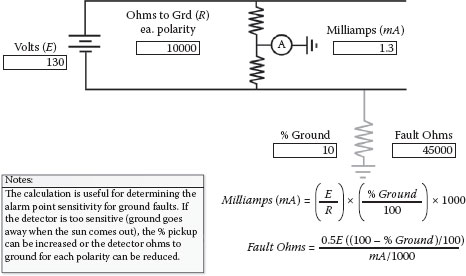
FIGURE 7.6
DC Ground Fault Ohms
The purpose of this guideline is to provide suggested procedures and schedules for the application, inspection, care, and maintenance of personnel safety grounds.
This guideline applies to all switchgear (draw-out circuit breakers and contactors) fed electrical systems (480 volts and higher). Typical short circuit currents for low voltage 480 volt switchgear systems are in the same range as the higher medium voltage systems (15,000 to 45,000 amps). This guideline does not apply to low voltage systems and loads that are fed from MCCs or distribution panels. The short circuit currents for these systems are usually lower than those available from switchgear-fed auxiliary power buses and feeders.
Personal grounds are applied on all three phases for the following reasons:
• Prevents the development of dangerous, even lethal, induced or inadvertent energizing voltages where the employee or contractor is working.
• Provides a short circuit current path that will result in the automatic tripping of any breakers involved in inadvertent or accidental switching energizations by in-service protective relays.
To accomplish this, portable grounds and grounding devices must be able to do the following:
• Mechanically withstand the short circuit electromechanical forces developed at the particular location.
• Have the thermal capacity to carry the short circuit current at the specific location. The calculation for determining the amount of time the safety grounding cable can carry short circuit current before it fuses open was discussed in Chapter 5.
Portable personal grounds are often made from flexible 2/0 conductors and clamps that have been approved for this purpose by vendor short circuit testing. Conductors of a size equal to 2/0 will fuse open in approximately 18 cycles with short circuit values of around 35,000 amps. To be effective, the fuse time of the personal grounds has to be longer than the protective relay clearing times (relay plus circuit breaker).
Personnel grounds must be connected directly to the station ground grid, where available, to reduce the circuit impedance and associated voltage rise during short circuit conditions. Additionally, all connections must be secure to reduce the contact resistance and corresponding heating of the connections and to ensure that the grounds can mechanically withstand the electromechanical forces when carrying short circuit currents.
Personal grounds should be located in between work locations and any possible sources of inadvertent energization. Where there is the possibility of induced voltages from neighboring energized conductors or circuits, the grounds must be located in the general proximity of the employee to prevent a voltage rise at that location from short circuit currents flowing in the adjacent energized circuits. It is not unusual for cables to share cable tray and duct banks with other energized circuits. For example, if motor cables are within 1 foot of another circuit and parallels the circuit for 900 feet, a 35,000 ampere ground or double line to ground fault in the neighboring circuit can induce 1 to 5 kV (depending on how the fault current returns to the source) into the out-of-service motor cables for the duration of the fault. Consequently, the end of the conductor that the worker is touching (motor end) needs to be grounded to prevent a hazardous voltage rise.
7.9.3 Special Grounding Considerations
The following locations in generating stations usually require special consideration for safety grounding:
• Low voltage side of generator step-up transformers: In this case, applying grounds on the low voltage side of the generator step-up transformer will usually not protect the worker from an inadvertent high voltage side energization even if the grounds are located in between the worker and the step-up transformer. The short circuit currents are normally too high for personal grounds; the clamps will not be able to withstand the electromechanical forces and the grounding cables will fuse open almost instantaneously from the high current values. Accordingly, high voltage side grounds must be applied to protect workers on the low voltage side of generator step up transformers. Grounds should also be applied on the low voltage side to protect workers from an inadvertent energization from the unit auxiliary transformer.
• Switchgear buses: The protective relaying fault clearing times for switchgear buses often exceeds the thermal capability of the personal grounds. Double grounds or large conductor sizes could be applied to increase the capability of the personal grounds, or a manufacturer’s grounding device could be used to ground the bus.
• Motor or feeder cables: Where motor or feeder cables share duct banks or cable trays with other energized or in-service feeders, there is concern about induced voltages from the neighboring circuits. If one of the adjacent circuits develops a ground fault or double line to ground fault, the corresponding high currents can produce a strong magnetic flux that links with the de-energized motor or feeder cables. This flux can easily induce voltages into the cables in the range of 1.0 to 5.0 kV, depending on the magnitude of the current, the distance from the motor or feeder cables to the adjacent circuit, the distance of parallel, and the path of the return short circuit current. Grounding the switchgear end aggravates this condition, as the full amount of induced voltage is referenced to ground at the other end. Grounding only the motor end prevents the worker from exposure to induced voltages at that end but not at the switchgear end. A switchgear-grounding device could be used for work at the switchgear end. For work at the motor end, the preferred method is to not ground the switchgear end of the cables. The cables can be disconnected, using properly rated and approved medium voltage gloves (as if it was energized), and personal grounds can be applied to the cables at the motor end immediately after they are disconnected. A reverse procedure can be used to reconnect the cables.
The following list provides induced voltages per 100 feet of parallel, with an adjacent energized circuit at various 60 Hz short circuit levels. It is assumed that the energized circuit is within 1 foot of the conductors where work is to be performed and the return path for the short circuit current is 100 feet away. If the circuit separation is increased to 10 feet, or if the short circuit return path is reduced to 10 feet, the induced voltages will be reduced by one-half. Conversely, if the circuit separation is reduced to 0.1 feet, or if the short circuit return path is increased to 1000 feet, the induced voltages will increase by a factor of 150%.
• 50,000 amps = 530 volts
• 40,000 amps = 424 volts
• 30,000 amps = 318 volts
• 20,000 amps = 212 volts
• 10,000 amps = 106 volts
• 5000 amps = 53 volts
• Personal grounds: Personal grounds should be inspected at 2-year intervals. Particular attention should be given to the clamps and terminations on each end of the cable. Cable clamping bolts should be checked for proper torque.
• Switchgear grounding devices: Grounding devices should be inspected every 2 years. Primary disconnect finger clusters should be inspected for proper spring tension, all mating surfaces should be inspected for acceptable silver plating, and all bolts involved in current carrying connections should be checked for proper torque values. Proper alignment of the poles and carriage should also be verified to ensure that racking in the grounding device will not damage the cubicle primary disconnects or racking mechanism.
• Switchgear ground and test devices: Ground and test devices should be inspected at 2-year intervals. In addition to the maintenance items delineated for grounding devices, ground and test devices should be thoroughly cleaned because approximately one-half of the device becomes energized under normal use.
• Ground disconnects: Ground disconnects used for personnel safety should be inspected on 2- to 3-year intervals. Disconnects should be inspected for proper spring tension, all mating surfaces should be inspected for acceptable silver plating (particular attention should be given to hinged areas), and all bolts involved in current carrying connections should be checked for proper torque values. Proper alignment and engagement of the poles should also be verified during this inspection.
• Personal grounds: During the inspection process, personal grounds should be micro-ohm tested to verify proper current carrying capability. A small amount of increased resistance during fault conditions will force a premature failure of the personal ground. For example, an increased resistance of 1.0 milliohms can cause an extra 100 kW of heating during fault conditions. The micro-ohm readings should be documented and compared to prior readings and other personal grounds for reasonableness. Differences should be investigated and resolved.
• Switchgear grounding devices: Grounding devices should be micro-ohm tested, during the inspection process, to verify proper current carrying capability. The micro-ohm readings should be documented and compared to prior readings for reasonableness. Differences should be investigated and resolved.
• Switchgear ground and test devices: In addition to micro-ohm tests as specified for switchgear grounding devices, ground and test devices should also be meggered and hi-pot tested during the inspection process.
• Ground disconnects: During the inspection process, ground disconnects should be micro-ohm tested to verify proper current carrying capability. The micro-ohm readings should be documented and compared to prior readings for reasonableness. Differences should be investigated and resolved.
7.10 Generator Automatic Voltage Regulators and Power System Stabilizers
The purpose of this guideline is to provide suggested procedures and schedules for the testing, inspection, care, and electrical maintenance of automatic voltage regulators (AVR) and power system stabilizers (PSS).
7.10.2 Automatic Voltage Regulators
Voltage regulators control generator excitation to maintain a constant terminal voltage as the machine is loaded. In general, var flows from a higher voltage to a lower voltage point on the electrical system. Therefore, it is important to maintain the desired generator output terminal voltage to control electrical system var flows.
7.10.3 Power System Stabilizers
PSS are installed on larger generators to dampen out intertie watt oscillations. Each generator has a local mode natural frequency at which it wants to oscillate, and the cumulative effect of operating a number of geographically dispersed generators in a network can create an intertie watt oscillation in the neighborhood of 1.0 cycle per second. The watt oscillations at system intertie points are undesirable, and the stabilizers act on the excitation system to dampen out the oscillations. On older units, the PSS are mounted in separate enclosures, and on newer excitation systems they may be incorporated into the same enclosure as AVR.
Accurate models of generators that feed the bulk power electrical system (100 kV and higher) and their associated controls are necessary for realistic simulations of the electrical grid. Baseline testing and periodic performance validation are required by regional transmission authorities to ensure that the dynamic models and databases that are used in the grid simulations to represent plant excitation systems are accurate and up to date. The testing involves off-line tests as well as full load dynamic testing and is normally performed by an excitation engineering specialist.
Each bulk power generating unit should have an excitation system model that was certified by dynamic testing. The certification document and associated testing reports should be maintained in the station file system.
Recertification testing of bulk power generators is normally performed during major unit overhauls at approximately 5-year intervals to ensure that the excitation model has not changed. New generation or units with modifications that could impact the excitation system model should be tested within 180 days of a start or restart date.
The following tasks should be completed prior to the full load dynamic testing:
• Where possible, megger and inspect CTs and PTs and associated wiring.
• Perform a thorough mechanical check of the switches, wiring terminals, and auxiliary relays and timers. Contacts should be cleaned as required. Dirt and contamination should be removed with a soft brush, or by low-pressure dry air, or vacuum.
• Electrical testing should be performed to prove that the voltage regulator is controlling properly and volts/Hz and reactive ampere limiters are functioning properly. PSS should be checked for proper tuning.
• Prove that tripping and alarm circuits will perform their intended operations.
• Make a final in-service test with the unit on-line to prove that the voltage regulator and PSSs are being supplied the proper currents and potentials, and, by observation, determine that the equipment appears to be functioning properly.
7.10.6 Generating Station Responsibilities
• Each generating station should maintain files on their excitation system certifications and routine tests. The associated station drawings must be maintained accurately. Files shall also be maintained on the investigation of voltage regulator and PSS failures.
• The individual generating station failure investigation reports should be sent to the generator excitation engineering support group in a timely manner for further analysis and possible upgrades to mitigate reoccurrence.
• Routine test cards or labels shall be visibly mounted on voltage regulator and PSS equipment. The cards or labels should show the date of the last routine test and the name of the responsible technician or engineer.
7.10.7 Excitation Engineering Responsibilities
• The excitation engineering group is responsible for reviewing and improving the design and calculating settings for generating station AVR and PSS systems.
• The excitation engineering group will also maintain files on key electrical drawings, instruction manuals, reference books, settings and associated calculations, and their analysis of excitation system failures.
• The excitation engineering group is responsible for developing routine test procedures for proving that voltage regulators and PSSs are functioning according to the intended design.
• The excitation engineering group will either perform the routine testing of AVR and PSS systems or will train station forces to perform the tests and provide testing and troubleshooting support as required.
• The excitation engineering group is responsible for performing dynamic testing for certification and recertification purposes.
Baker, Thomas, EE Helper Power Engineering Software Program, Laguna Niguel, CA: Sumatron, Inc., 2002.
Baker, Thomas, Electrical Maintenance Guidelines, Laguna Niguel, CA: Sumatron, Inc., 2003.
EPRI, Power Plant Electrical Reference Series, Vols. 1–16, Palo Alto, CA: Stone & Webster Engineering Corporation, 1987.
Kerszenbaum, Isidor and Maugham, Clyde, Utilization of Repetitive Surge Oscillograph (RSO) in the Detection of Rotor Shorted-Turns in Large Turbine-Driven Generators, Annapolis, MD: IEEE Electrical Insulation Conference, 2011.
Klempner, Geoff, and Kerszenbaum, Isidor, Handbook of Large Turbo-Generator Operation and Maintenance, Piscataway, NJ: IEEE Press, 2008.
Sumatron, Inc., Generator Rotor Shorted Turn Analyzer Instruction Manual, Laguna Niguel, CA, 2004.
Westinghouse Electric Corporation, Applied Protective Relaying, Newark, NJ: Silent Sentinels, 1976.