
Chapter 11
Sinusoidal Oscillators

(a) BJT phase-Shift oscillator (b) Equivalent circuit
Chapter Outline
The concepts introduced in this chapter are:
- Positive feedback in amplifier circuits
- Condition and frequency of sinusoidal oscillations
- Various types of oscillator circuits
- Amplitude and frequency stability of sinusoidal oscillators
11.1 INTRODUCTION
Generation of sinusoidal oscillations of a given frequency is highly essential in any electronic circuit. Using the concept of positive feedback generates such sinusoidal oscillations. Active devices such as transistor, FET or Op-Amp (operational amplifier) are employed in the generation of sinusoidal oscillations. The circuit configurations vary depending upon the frequency of operation, application and so on, but basically the principle of operation is the same for all such sinusoidal oscillators. Generating sinusoidal oscillations is nothing but producing the required signal without any given input to a transistor circuit. This is possible since a transistor is not an amplifying device but a device that converts dc energy into ac energy at required frequency. In a transistor amplifier, the device converts the dc power into ac signal of input frequency and adds this to the input signal to achieve the required amplification. The same is the case with oscillators also except that since there is no signal available at the input, the converted signal is right available at the output of the circuit. The condition of oscillation and frequency of oscillation depends on the principle known as Barkhausen criterion. The stability of both amplitude and frequency is of prime concern since the device employed here is a transistor whose parameters are not constant. This concept of stability is also considered in this chapter.
11.2 BARKHAUSEN CRITERION
In order to understand the concept of generation of sinusoidal oscillations, the negative feedback amplifier is considered where the closed loop is broken at the stage of mixing at the input of the amplifier as shown in Fig. 11.1. Starting from node 1 of the circuit, the input signal Xi is multiplied by A, the amplification of the basic amplifier to produce the output signal of the amplifier. This signal is further multiplied by β, the transfer ratio of the feedback circuit to generate the feedback signal. So, the input signal is multiplied by Aβ to achieve feedback signal. In a negative feedback the input to the basic amplifier is the difference of the source signal and feedback signal. The same can be presented as the input signal is sum of the source signal and phase-shifted feedback signal (phase shift being 180°), that is, the new feedback signal, X′f, is equal to − Xf,
In other words, the signal at node 2 of the circuit is achieved after multiplying the input signal at node 1 by − A β. That is, the loop gain of the network is

Fig. 11.1 Barkhausen Criterion
If the loop and its gains are so adjusted such that X′f is exactly identical to Xi, that is,
implies that loop gain is equal to 1, that is,
Then, node 2 can be connected to node 1 without disturbing the output and removing the input signal. As far as the basic amplifier is concerned, it is not concerned from where the source signal is derived. It is supposed to amplify the signal that is available at the input. So, if the above condition is satisfied for a given circuit, the output is available even though the input signal is removed. This is nothing but the concept of sinusoidal oscillations.
Considering Eq. (11.3), which states that the new feedback signal should be identical to the input signal, does not only imply that amplitudes are same, but along with amplitude, frequency, phase and also the shape of the signal should be exactly equal to that of the input signal. Then and only then, the above oscillations are possible for generation.
Basically the condition required for oscillations to sustain is that the loop gain should be equal to unity. This guarantees oscillations. If the loop gain is less than unity, then the feedback is said to be negative feedback, the one that is employed in amplifiers. In this type of feedback, if input is not connected, since the loop gain is less than 1, the signal slowly decreases and dies down to zero very soon. In a feedback amplifier, the input provides this loss in the signal, thus maintaining the output at a given level of the signal. Because of this reason, the gain of the feedback amplifier is small with feedback. Some of the power from the output is utilised to compensate for the loss in the signal due to low loop gain. When the loop gain is exactly unity, the oscillations are possible since no signal is lost and amplifier continues its action without any loss in the energy.
When the loop gain is large compared to 1, the signal is large compared to its initial value after the signal travels by one closed loop. This continues and as time extends to infinity, the output signal should build up in amplitude and will have to tend to infinity. In practice, infinity signal is not really possible since a source of infinite energy is not practicable. The energy drawn from the dc power supply of the circuit is limited and the amplitude of the signal has to be saturated at this energy level. So, when the loop gain is large compared to unity, the output increases to a level of saturation and is limited at this level.
The frequency of oscillation depends on the phase around the closed loop. The phase around the closed loop should be 0 or multiples of 2 π radians. Since the feedback circuit employs reactive components, the phase introduced by this circuit depends on the frequency of operation. Or, putting it the other way round, the frequency at which the phase introduced by this circuit in association with the amplifier circuit is 0 or multiples of 2π radians, is the frequency of oscillation.
Based on the above discussion, the Barkhausen criterion can be stated as: To maintain oscillations in a transistor circuit, the loop gain should be more than unity. In other words, if the product of magnitude of transfer gain of the transistor amplifier and that of the feedback factor of the feedback network is more than unity. If the loop gain is less than unity, the oscillations will die and output will soon be zero.
The frequency of oscillation is determined by the phase shift condition. The phase shift around the closed loop starting from input of the amplifier to output of the amplifier to the input of the feedback circuit to the output of feedback circuit through input mixer back to input of the amplifier should be either zero or integral multiples of 360° (2? radians). In other words, the phase of the input signal and phase of the signal after traversing through amplifier, feedback circuit and mixer should be exactly the same, i.e., the two signals should be in phase.
To be more specific, the frequency at which the two signals will be in exactly same phase is the frequency of oscillation. The frequency component which satisfies this condition is picked up from the thermal noise available in the components of the circuit. The magnitude of the loop gain determines the condition of oscillation (loop gain unity) and the phase around the closed loop determines the frequency of operation.
When the loop gain is unity, the gain with feedback is
Or, in other words, when Af tends to infinity it means that the output is available even though the input signal is zero or absent, which is what oscillation means.
The Barkhausen criterion is true for whatever may be the signal shape, sine, triangular or square. But, the principle is only applicable for sine signals since even though the amplifier is able to handle any signal under consideration, the feedback network comprising the passive components cannot maintain the shape of the signal when the signal is transmitted through it. Only sinusoidal signals can maintain shape without any distortion, even though amplitude and phase suffer, when passed through a passive network. This is the reason why Barkhausen criterion is applicable to only sinusoidal signals.
Practical Limitation: If the minimum condition for oscillation, the loop gain equal to unity, is met sinusoidal oscillations are guaranteed theoretically. But, in practice, there is a limitation. The small signal gain of a transistor is not constant and depends on various factors and constraints such as temperature, ageing, voltage and so on. So, even though the circuit is designed to oscillate with loop gain unity, when circumstances change consequently, there is a chance that amplifier transfer gain A may droop down pulling the loop gain below unity. This causes the oscillations to damp down to zero very soon. This is not an impossible condition but will occur very frequently in practice. So, if loop gain is chosen to be exactly equal to unity, this limitation will make the oscillations die down.
To avoid the above limitation of sinusoidal oscillation, the loop gain is chosen slightly greater than unity. This selection will ensure that loop gain will never be less than 1 and oscillations are assured. Since the loop gain is more than 1, the output increases and is limited to saturation of the amplifier.
In practice, the magnitude of the loop gain around the closed loop consisting of amplifier, feedback network and mixer is chosen to be slightly more than unity. This leads to the fact that the magnitude of the output oscillations grow. But, this growth of the magnitude of oscillations is finite since the amplifier reaches saturation at a given voltage and the non linearity of the device restricts the growth of the signal at the output. Thus, the magnitude of the output signal is limited by the non linearity of the amplifier.
Types of oscillators: Broadly, the oscillators can be classified as sinusoidal and relaxation— square or sawtooth. They can be classified based on the mode of operation as feedback type and negative resistance type. The types of sinusoidal oscillators can be classified as:
- Tuned circuit or LC oscillators—Colpitt, Hartley, Clapp
- RC oscillators—phase shift, Wein bridge, tuned collector (resonant circuit)
- Crystal oscillators.
11.3 PHASE-SHIFT OSCILLATOR
The phase-shift oscillator is a very good example of the criterion discussed in the above sections. The basic amplifier, either BJT or FET, introduces a 180° phase shift between the input and output of the amplifier in CE or CS configuration. The remaining 180° phase shift, so as to satisfy the Barkhausen criterion, is to be introduced by the feedback network. The feedback network is chosen as resistor-capacitor network in case of a phase- shift oscillator. If the capacitor is ideal, the phase shift across it would be 90° and so, two capacitors in series might have been sufficient to introduce the additional phase. But, in practice, no capacitor is ideal and has some leakage conductance, the phase shift is always less than 90o. So, one requires at least three capacitors to achieve the requirement of 180o phase. Three capacitors in series with resistors in shunt is the feedback network chosen for this phase-shift oscillator. The oscillator oscillates at a frequency when the phase of this feedback network is exactly 180°. For any other frequency, the oscillations cannot be sustained since the phase condition is not satisfied.
Figure 11.2(a) shows the circuit diagram of a phase-shift oscillator using FET. In Fig. 11.2(b), FET is replaced by its small signal model for analysis. Applying the known network principles to the feedback network, its transfer ratio can be derived as the ratio of V′f and Vo, which is nothing but β and be given as
where α = 1/ ωRC, ω = 2 πf. The phase shift of − β would be 180° only when the above transfer function is real. So, equating the imaginary term in the denominator of the ratio to zero, the condition can be satisfied. Or, in other words, the frequency of oscillation is the condition at which the transfer ratio would be real. Imposing this condition on the above transfer ratio,

Fig. 11.2 RC phase shift oscillator — FET
or,
at this frequency of operation, the magnitude of the transfer ratio of the feedback network can be derived to be
Therefore, applying the Barkhausen criterion to this circuit, which states that loop gain, ∣ Aβ ∣ should be at least equal to unity, the gain of the amplifier without feedback should be 29 or slightly more. That is, the condition for oscillation of a FET phase-shift amplifier is
In other words, a FET is to be chosen in this type of oscillator with an amplification factor μ > 29.
In the above discussion, since a FET is employed as the active device, the input impedance of the device being very large, the loading of the feedback network is not considered. But when a phase-shift oscillator is to be realized with a BJT, whose input impedance is of medium range, the loading of the feedback network cannot be neglected and is to be taken care of. So, the circuit diagram of the oscillator with BJT is slightly modified such that the effective resistance offered by the third capacitor would be still R. So, the return resistor value is chosen to be equal to R3 such that this resistor, in series with the input impedance of the basic amplifier circuit, would have a value equal to R. Such a configuration of the phase-shift oscillator along with its small signal equivalent circuit is as shown in Fig. 11.3.
As one can see from the circuit, voltage shunt feedback is employed in this circuit while voltage series feedback is employed in the FET circuit. The value of R3 is chosen such that
where Ri ≈ hie is the input impedance of the amplifier. In the analysis of the transfer ratio of the feedback network, the effect of the resistors, R1 and R2 and the output resistance Ro are neglected. With these assumptions, the analysis of the feedback network is done as in the case of FET circuit and the frequency of oscillation can be given as
and condition for oscillations as
where k = Rc / R.
Applications: By appropriate selection of the R and C values, the frequency of oscillation can be achieved from few hertz to several hundred kilohertz. So, these type of oscillators cover the audio frequency range. In the megahertz frequency range, surely the LC oscillator circuits take the upper edge. Varying the RC combination can vary the frequency of oscillation. The best way is to vary all three capacitor values simultaneously. So, ganged capacitors are employed where frequency variation over large range is required. Resistor variation is not generally accepted since varying the R value varies the condition for oscillation as hfe is a function of R, as seen by Eq. (11.12). This may alter the amplification and the condition for oscillations may not be satisfied for a given value of R. The transistor is operated in class A region in order to minimise distortion in the signal.

The RC phase-shift oscillator provides good stability. Circuit can be used to produce frequencies up to VLF. The circuit does not require inductances or transformers. The limitations of this circuit are that it cannot be used at high frequencies, as feedback is small it is not easy to start oscillations and the output is small comparatively.
11.4 RESONANT CIRCUIT OSCILLATOR
A RF transformer, which can couple the output of an amplifier to its input via a positive feedback, is another example of a sinusoidal oscillator. Such an oscillator is called resonant circuit oscillator since the frequency of oscillation is nothing but the resonant frequency of the tank circuit, which is employed in the output of the amplifier. Resonant circuit oscillators employing FET and BJT are as shown in Fig. 11.4.
Since the basic amplifier has a phase-shift of 180° between its input and output, the transformer is so connected in the circuit such that the phase shift between its primary and secondary is also 180°, as shown in Fig. 11.4. With reference to the circuit with FET, consider Fig. 11.4(a) in which FET is employed. In this circuit, r represents series resistance of the transformer winding. This takes into account the losses in the transformer. In general, value r is very small and can be neglected. The resonant frequency of oscillation can thus be written as
At resonant frequency, the impedance of the resonant circuit is purely resistive and the reactance is zero. At this frequency of resonance the phase shift condition around the loop is satisfied, i.e., the phase between input of the FET and output and phase across the transformer is 180°. Thus, total phase shift around the loop is 360° satisfying the required condition and finally the oscillations at this frequency are sustained.
The mutual inductance between the windings is also considered and this leads to the fact that the amplification factor of the FET should be
for the loop gain −Aβ to be equal to unity.
Taking r into consideration, the resonant frequency is given as

Fig. 11.4 Resonant circuit oscillator
and the condition for oscillation to sustain is
The frequency of oscillation and condition for oscillation are independent. The frequency of oscillation is the frequency at which the loop phase shift is zero or in multiples of 360°. Calling such an oscillator as resonant circuit oscillator instead of phase-shift oscillator is purely artificial. In fact, all types of oscillators discussed under this head are phase-shift oscillators.
The operation of the amplifier is class C. The bias for a resonant circuit oscillator is obtained from a parallel RgCg combination in series with the gate. The gate and source of the FET act as a rectifier and if the time constant RgCg is large compared with one period, the gate capacitor will charge up essentially to the peak gate swing. This voltage across Cg acts as the bias, and the gate is therefore driven positive only for a short interval at the peak of the swing. The voltage at the gate is a large sinusoid, and since its peak value is approximately at ground potential, the gate is clamped to ground.
The gate bias is zero initially when the circuit is switched on and the FET operates with large gm. Then the loop gain is greater than unity and the amplitude of oscillation starts growing. The gate current is drawn and clamping takes place and the bias automatically adjusts itself so that its magnitude equals the peak of the gate voltage. As the bias becomes more negative, the value of gm decreases and finally the amplitude stabilises itself at that value for which the loop gain for the fundamental frequency is reduced to unity. The value of gm is considered to be the minimum value required at zero bias in order for oscillations to start. It also can be interpreted as the average value of transconductance, which determines the amplitude of oscillation.
Resonant circuit oscillator can also be built with a transistor and such a circuit is shown in fig. 11.4 (b). As in the case of FET circuit, the transistor operates in class C mode. The transistor is connected in self-bias configuration. R2 Cb combination will control the base current.
11.5 HARTLEY AND COLPITT OSCILLATORS
Hartley, Colpitt or Clapp oscillator can be derived from a general configuration of the positive feedback circuit when Barkhausen criterion is satisfied. The general configuration of such an oscillator circuit is as shown in Fig. 11.5. The active device employed in this circuit may be a BJT or a FET or an operational amplifier. The active device is assumed to have infinite input impedance. The devices which have such high input impedance are FET or Operational Amplifiers. In Fig. 11.5(b), the device is assumed to have a gain of −Av and output resistance of Ro. The feedback employed in such a circuit is voltage series.
To determine loop gain, the transfer gain of the amplifier and feedback factor is to be calculated. −Aβ is the loop gain where A is the amplifier gain and β is the feedback factor. The input terminals of the amplifier are 1 and 3 while the output terminals are 2 and 3. Thus, as seen from the figure, the load impedance of the circuit is Z2 which is in parallel with series combination of Z1 and Z3.
Thus,

The amplification without feedback can be given as
and the feedback factor is
Thus, the loop gain can be derived to be
Assume that all the three impedances are pure reactive without resistive or conductive loss components, Z = jX, where X is the reactance. X = ωL, if inductive or X = − 1/ωC, if capacitive. Then, Eq. (11.20) can be rewritten as
For loop phase shift to be zero, the loop gain should be real and this is possible when
which is the frequency at which the sustained oscillations are achieved.
Substituting this into Eq. (11.20),
or,
From the above equation it can be assessed that X1 and X2 should be of the same sign if the loop gain is to be unity or slightly more. That is, both reactances must be either inductive or capacitive. If one is inductive and the other is capacitive, the loop gain would be negative and the condition of positive feedback is not satisfied. Obviously, the other reactance X3 should be of opposite sign. That is, when X1 and X2 are chosen to be inductive, X3 should be capacitive or if X1 and X2 are chosen to be capacitive, X3 should be inductive. Thus, the condition for oscillation can be derived to be
If X1 and X2 are chosen to be inductive and X3 capacitive, the oscillator is referred to as Hartley oscillator and if X1 and X2 are chosen to be capacitive and X3 inductive, the oscillator is called Colpitt oscillator. While working with the Hartley oscillator, the mutual inductance between L1 and L2 is to be considered and cannot be neglected.
The essential features of LC oscillators are:
- resonant or tank circuit which determines the frequency of oscillations
- amplifier, which amplifies the oscillations produced by the tank
- network, which provides positive feedback to the tank.
Tuned LC oscillators are used at high frequencies. At low frequencies, the inductor and capacitors would be bulky and so, are not suitable. Thus, RC oscillators are employed at low frequencies. The limitation of both RC and LC oscillators is stability of oscillations.
Colpitt oscillator: Detailed analysis of the Colpitt oscillator is difficult since
- low input impedance shunts the Z1 and expression is complicated
- oscillation frequency is beyond audio range and so simple low-frequency h-parameter model is not valid and a high-frequency hybrid Π model is to be employed.
For a Colpitt oscillator, the frequency of operation can be put as
or,
where,
and the condition of oscillation is
Colpitt oscillator finds large number of applications within a frequency range of 1 MHz to 500 MHz. It is generally used commercially as signal generator above 1 MHz frequency. Hartley oscillator: Hartley oscillator is used a great deal in transistor radios and other receivers. For a Hartley oscillator, the frequency of operation can be put as
where, L = L1 + L2 + 2M …(11.32)
and M is the mutual inductance between the two inductances.
And, the condition of oscillation is
or, considering the mutual inductance, it can be given as
The transistor versions of both the circuits are as shown in Fig. 11.6. The procedure of analysis of such circuits is in similar lines as discussed above, but is very elaborate and complex as the input impedance of the BJT amplifier shunts with the Z1 Also the range of frequency operation is above audio-frequency range. The situation is more complex when the high-frequency oscillators are to be analysed since hybrid n model is supposed to be used and low-frequency h-parameter model is no more valid. If the performance of the two Hartley and Colpitt oscillators is same, Colpitt oscillator is preferred to Hartley since bulky inductances can be avoided and also the problem with mutual inductance can be neglected.

Fig. 11.6 Transistor Colpitt and Hartley oscillators
The advantages of Hartley oscillator are the following:
- Instead of two separate coils L1 and L2, a single coil of bare wire can be used and coil grounded at any desired point along it
- Frequency can be adjusted by variable capacitor C.
Clapp oscillator: Clapp oscillator also finds same applications as the Colpitt oscillator but its stability is very large compared to Colpitt oscillator. Thus, in practice, Clapp oscillator is used rather than Colpitt oscillator.
The drawback of Colpitt oscillator is that its frequency stability is very poor. This is because of the frequency of oscillation depends on the capacitances C1 and C2. But these two capacitances are shunted by the stray capacitances of the transistor. So, the output frequency is not the same as that of the designed value and also not stable since stray capacitance of a transistor is not stable. Thus, the frequency stability of Colpitt oscillator is very poor. This drawback is overcome by use of one more capacitor C3 in series with the inductor and choosing C3 to be very small compared to either C1 or C2. Thus, if C3 ≪ C1, C2, then the stability of the circuit is improved to a very large extent since the frequency of oscillation is only dependent on C3 but not on other capacitors or stray capacitances of the transistor.
As shown in Fig. 11.7, the circuit of Clapp oscillator has an additional capacitor C3 in series with the inductor. Then, assuming that all the three capacitors are in series, the frequency of oscillation can be given as
where,
when C3 ≪ C1, C2, C ≈ C3 and thus

Fig. 11.7 Clapp oscillator
11.6 WIEN BRIDGE OSCILLATOR
An oscillator that uses a balanced bridge in the feedback path is another example of the sinusoidal oscillator. Wien bridge is ideally suited for this purpose and the frequency stability of the circuit is very much improved compared to the previous types of oscillators. Since the transfer gain of the amplifier with feedback tends to infinity for an oscillator, this condition can be achieved when the input to the oscillator tends to zero and the output is still a finite sinusoid. The two terminals of the bridge, which are equipotential in the balanced condition, are returned to the input of the active device, an Op-Amp. The bridge offers equipotential between the two terminals only when it is balanced and it is balanced when the condition on the arm impedances is satisfied. This condition on arm impedances is once again only satisfied at a particular frequency since capacitive reactances are involved. That is, the frequency of oscillation is the frequency at which the bridge is balanced.
The circuit of a Wien bridge oscillator is as shown in Fig. 11.8. The active device referred here is Op Amp which has infinite input impedance. Also Op Amp is assumed to have very large voltage gain. In addition, the output impedance of the device is negligible. Thus, voltage gain of the amplifier is constant since loading of the device is neglected. This is true over entire range of frequencies of interest. The loop gain of the circuit can be determined by breaking the loop at P and voltage V′o is assumed to be applied between 3 and 4. The loop gain of the circuit can thus be calculated as
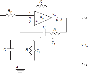
Fig. 11.8 Wien bridge oscillator
From Fig. 11.8,
and A = Av, positive gain. So,
Z1 is the series combination of R and C, and Z2 is the parallel combination of R and C. Evaluating the above expression and equating the imaginary portion of the expression to zero since the phase of the expression is required to be zero for sustained oscillations, the frequency of oscillation can be derived to be
or,
If a null is desired, Vi = 0 implies
But in this discussion, when the bridge is used as feedback network, the loop gain should be unity and the phase should be zero. Since Av is positive, phase of − β should be zero, but the magnitude should not be zero. If magnitude is zero, the loop gain magnitude would be zero and the oscillations are not at all possible. Since Z2 / (Z1 + Z2) = 1/3, the magnitude of R2/(R1 + R2) should be smaller than 1/3. Let us assume that δ is a positive number greater than 3 such that
Then,
or, at balance condition, V2 = (1/3) V′o and so,
which implies from the fact that − Aβ = 1,
The frequency of oscillation is precisely the null frequency of the balanced bridge. At any other frequency, V2 is not in phase with V′o and, therefore, Vi is not in phase with V′o and the condition of − Aβ = 1 is not satisfied. Varying simultaneously the two capacitors in gang can vary the frequency of oscillation. If the frequency range is to be changed, this can be accomplished by varying the two resistors R.
11.7 CRYSTAL OSCILLATOR
A very highly stable frequency signal can be generated with the help of a crystal oscillator. A crystal oscillator also utilises the principle of general oscillator circuit similar to that of Colpitt or Hartley oscillator except that instead of inductance, a piezoelectric crystal is employed. Such type of oscillators can generate very high frequencies, of the order of few megahertz. The drawback of the circuit is that the frequency of the sinusoidal signal generated is not variable. The oscillator can oscillate only at the natural resonant frequency of the crystal chosen and no oscillations are possible at any other frequency whatever may the changes of the other components of the circuit. So, the frequency stability of the circuit is high. If a change in frequency is required, one has to replace the crystal with the desired natural resonant frequency. Such oscillators find large applications in the communication equipment, for example, in the receiver, where very high stable frequency oscillations are required.
Piezoelectric effect is an elctromechanical phenomenon. Some natural crystals available exhibit such electromechanical effect. If mechanically the crystal is vibrated, it develops an ac electric signal variation of natural resonant frequency at the ends of the faces of the crystal. Or, if an ac signal is applied across the faces of the crystal, the crystal vibrates mechanically. Crystals such as Rochelle salt, quartz and tourmaline exhibit such piezoelectric effect. The natural resonant frequency of the crystal depends on the dimensions of the crystal as well as mechanical orientations of the crystal structure. The frequency is inversely proportional to the thickness of the crystal and so as the frequency of oscillation increases, the thickness of the crystal decreases. The mechanical stability of the crystal as well as the sensitivity of the crystal are vital in selection of crystal in sinusoidal oscillators. Mechanically, Rochelle salts are very weak even though their sensitivity is very high. Rochelle salts have greatest effect; for a given ac voltage they vibrate more than others, but they are mechanically the weakest and break easily. They are used in microphones, phonograph pick-ups, headsets, loudspeakers and so on. But, they are not adoptable in these oscillator circuits. On the other hand, tourmaline has high mechanical stability but very low sensitivity. Tourmaline is most expensive and is used in general at very high frequencies. A compromise is the quartz crystal whose mechanical stability and sensitivity are medium and reasonably good. Also, quartz is readily available. So, Quartz is very widely used as crystal in sinusoidal oscillators, filters and so on.
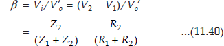
Natural shape of quartz is hexagonal with pyramids at ends. To get a usable crystal, it has to be recast into rectangular slab slices. There are different cuts employed in this process like X cut, Y cut, AT cut and so on. The frequency of the crystal is inversely proportional to the thickness of the slice. The resonant frequency and quality factor depend on the dimensions of the crystal, surface orientation with respect to axis, and orientation of the mount. Quartz crystals are available from few kHz to few MHz and quality factor from several 1000s to 100s of thousands. These extraordinary high values of the crystal Q make the crystal oscillator extremely stable with respect to time and temperature. The electric symbol, electric equivalent and the reactance characteristic of a quartz crystal are as shown in Fig. 11.9.
A look at the figure shows that the crystal has series resonance as well as parallel resonance. The three elements R, L and C are the characteristics of the natural crystal and C¢ is the capacitance of the two electrodes supporting the crystal. It can be observed easily from the reactance characteristic that the crystal is capacitive up to series resonant frequency and also above a parallel resonant frequency. Between the two resonant frequencies, the crystal exhibits inductive reactance characteristics. The difference between the series and parallel resonant frequencies is extremely small and in the figure, it has been exaggerated for the purpose of understanding. In other words, the two resonant frequencies are too close such that one can say that almost the crystal exhibits inductive characteristic at a single frequency. This is the reason for a very high value of the quality factor Q. Since Q is extremely high, the bandwidth is very small and so, highly stable oscillations are possible. In practice, R is of the order of few kiloohms, L is of the order of few Henrys and value of C the is very large compared to C.
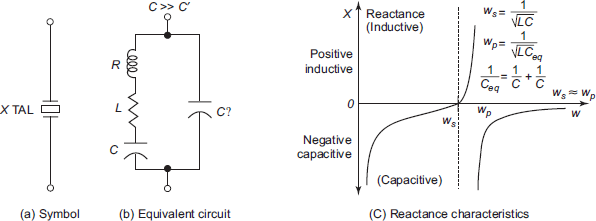
Fig. 11.9 A piezoelectric crystal
The impedance of the crystal can be derived as (neglecting the loss factor)
where ωS is the series resonant frequency taking R, L and C in series into consideration and ωp is the resonant frequency taking into parallel electrode capacitance. The values of the two resonant frequencies can be given as
since C ≫ C′, ωs ≈ ωp. Thus, when ωs < ω < ωp, the reactance is inductive and outside it is capacitive.
Figure 11.10 shows a typical example of a crystal oscillator that employs a 1 MHz quartz crystal. In this circuit, which is basically a Hartley oscillator, Z2 is the output tank circuit, which is a tank circuit tuned inductive, Z3 is the stray drain to gate capacitance of the FET and Z1 is the quartz crystal. So, the crystal only oscillates when Z1 or crystal is inductive, that is, at resonant frequency of the crystal and nowhere else. This is possible since ωs »» ωp and the frequency of oscillation is essentially determined only by this but not by any other parameter of the circuit.
The stability of a quartz crystal would be around 1 part in 106, that is, 0.0001% per day. Such crystals are employed in wristwatches. The stability of a crystal oscillator would be around 1 part in 1010 per day and so the variation is very low, there would be a variation of 1 in 300 years. A crystal oscillator is highly stable and is available up to 10 MHz of frequencies. However, the disadvantages are that the frequency cannot be varied and can be used only for low-power applications.
11.8 AMPLITUDE AND FREQUENCY STABILITY
Amplitude stabilization : Amplitude stabilisation of the sinusoidal oscillator is required to maintain the loop gain magnitude constant. With respect to temperature, ageing of the transistor and other components, even though the ratio, β is assumed to be constant, A is to be stabilized. The stabilization of this amplification parameter can be achieved by various methods. Use of temperature-sensitive resistors such as a sensistor or a thermistor is the best choice.
Considering the circuit of a Wien bridge oscillator, Fig. 11.9, a sensistor, a resistor with positive temperature coefficient, can replace R2 in the circuit. The sensistor is a device whose resistance increases with temperature. At room temperature, it operates as a simple resistor. When temperature increases, as one can anticipate, A increases, making the loop gain magnitude more than unity. This can be checked by the regulation mechanism of the sensistor. Since the resistance of the sensistor increases, β decreases and the loop gain is stabilised.

On the other hand, when temperature decreases, the amplification A decreases and because the resistance of sensistor decreases, β increases, compensating the decrease in the amplification and stabilising the loop gain − Aβ.
If a device that has negative temperature coefficient like a thermistor is to be employed, it should replace R1 and same kind of stabilisation can be anticipated and the loop gain can be maintained almost constant at unity.
Frequency Stabilization: In any sinusoidal oscillator, the frequency of oscillation is determined by the condition that the phase shift around the loop should be zero or multiples of 2π radians. So, there is a possibility that the frequency of an oscillator may change erratically since the phase around the loop depends on the performance of various components in the circuit. The stability of oscillations in frequency is of prime concern in the design of any circuit and frequency stability of an oscillator can be defined as a measure of its ability to maintain as nearly fixed as possible over as long a time interval as possible. The values of the circuit parameters cannot be maintained constant with respect to time since, for example, with respect to a transistor, the parameters are time and temperature dependent. So, to achieve frequency stability by maintaining the component values constant is almost impossible. Also, the stray component values are a great problem at estimating the exact values of the components involved in the circuit. The solution is to make the frequency condition as far as possible to depend not on the temperature of time-dependent components, but on the passive components such as a resistor or a capacitor. For example, when a phase-shift oscillator is considered, the frequency of oscillation depends on the resistor and capacitor values, which are almost constant irrespective of time and temperature.
The frequency stability of the circuit depends on the ability of each component to maintain constant phase irrespective of frequency variation. Thus, variation of phase of the component θ with respect to frequency ω, that is, dθ/dω serves as a measure of the independence of the frequency of all other features of the circuit. The frequency stability improves as dθ/dω increases. In the limit dθ/dω tends to infinity. In other words, whatever may be the phase variation, the frequency variation is zero or negligible, the circuit becomes independent of these variations and the frequency of oscillation is maintained constant.
SUMMARY
- Sinusoidal oscillators are electronic circuits that produce oscillations of sinusoidal nature on their own.
- Sinusoidal oscillators work on the principle of Barkhausen criterion.
- Barkhausen criterion states that oscillations are possible only when the loop gain is unity or more.
- The frequency of oscillation of an oscillator is determined on the condition that phase around the closed loop should be zero or integral multiples of 2π radians.
- RC phase-shift oscillators can be built using either BJT or FET. These oscillators are useful at low frequencies. No inductors or chokes or transformers are utilised in these circuits.
- Resonant circuit oscillators operate at the resonant frequency of the tank circuit. The coupling between the output and input is via a RF transformer.
- At high frequencies, Hartley and Colpitt oscillators are used. Hartley oscillator has the drawback of mutual inductance and losses with bulky inductors. Colpitt oscillator’s frequency stability is poor due to shunting of stray capacitance with feedback network.
- Clapp oscillator relaxes the limitation of Colpitt oscillator by the use of additional capacitor in series with the inductor.
- Wien bridge oscillator employs a balance bridge in the feedback circuit. Its amplitude stability is good.
- Piezoelectric effect is an electromechanical phenomenon. Natural crystal like quartz exhibits this effect. Mechanical vibrations are converted to electric oscillations or vice versa.
- Quartz crystals are employed in sinusoidal oscillators. These oscillators have extreme frequency stability and are available up to large frequencies of MHz range.
11.1 Derive an expression for frequency of oscillation of a RC phase-shift oscillator using a transistor.
Solution In case of a transistor phase-shift oscillator voltage-shunt feedback is employed.
The circuit from which loop gain is going to be calculated is as shown below:

Assume RTH = R1∥ R2 ≫ Ri and hoe = hre = 0
For unity loop gain we need ib = I3.
Replacing the current source by its Thevenin’s equivalent, we will get the circuit as below.

Writing three KVL equations,
− hfe·ib·RC = (R + RC − JXC) I1 − RI2
O = − RI1 + (2R − JX)I2 − RI3
O = − RI2 + (2R − JX) I3
These can be arranged in matrix form as

where ![]() . Let
. Let ![]() and K = RC/R.
and K = RC/R.

|
= |
R3(1 + K − Jα)[(2 − Jα)2 − 1] + 1(− 1(2 − Jα)) |
|
= |
R3[(1 + K − Jα)[(4 −α2 − J4α − 1) − 2 + Jα] |
|
= |
R3[(1 + K − Jα)[(3 −α2 − J4α) − 2 + Jα] |
|
= |
R3[1 + 3K − (5 + K)α2] − J[(6 + 4k) α − α3] |

To find frequency of oscillation, phase-shift should be zero.
For phase-shift to be zero, imaginary term is to be zero.

Substituting ![]() in equation (1)
in equation (1)

∴ hfe > 4K + 23 + 29/K for sustained oscillations. To find minimum value of hfe.

So, in order to get sustained oscillations, a transistor with hfe less than 45 should not be used.
11.2 Derive an expression for frequency of oscillation of a FET based RC phase-shift oscillator.
Solution A FET based RC phase-shift oscillator is as shown in the figure. It uses voltage-series feedback. The circuit used for the derivation of frequency of oscillation is as shown below:

Writing KVL equations in meshes (1), (2), (3), letting X = 1/ωC
Vo = (R − JX) I1 − RI2
O = − RI1 + (2R − JX)I2 − I3R
O = − RI2 + (2R − JX)I3
These can be written in matrix form as below.

where ![]()


For 180° phase shift make imaginary term = 0.

At this frequency of oscillation ![]()
We want ∣ −Aβ ∣ ≥ 1 to get sustained oscillations

∴ The gain of the amplifier must be at least 29.
![]() . By using voltage division
. By using voltage division
![]()
11.3 For the tuned-drain oscillator, show that the frequency of oscillation is given by  and that for the loop gain to be equal to unity, the FET must have mutual conductance given by
 ![]() where μ is amplification factor, r is equivalent series resistance of the coil primary, M is the mutual inductance of the coil.
where μ is amplification factor, r is equivalent series resistance of the coil primary, M is the mutual inductance of the coil.
Solution

The equivalent diagram is as shown below, replacing FET with its equivalent circuit.

For unity loop gain V2 = Vgs
![]() where z is the impedance of the tuned circuit.
where z is the impedance of the tuned circuit.

Now, the loop gain is given by

The loop-phase shift is zero when, imaginary part = 0.

at this frequency of oscillation, loop gain is to be unity

Hence proved.
11.4
- A RC phase shift oscillator uses the feedback network shown. Prove that

- Show that the frequency of oscillation is
 and that the gain must exceed 3.

Solution Let ![]()
Writing KVL equations in two meshes.


To get frequency of oscillator make imaginary part = 0.

At this frequency of oscillation ![]()

∴ to get sustained oscillations A should be more than 3.
11.5
- Derive an expression for impedance of a crystal.
- Prove that the ratio of the parallel to series resonant frequencies is given by

- If C = 0.02 pF and C′ = 4.0 pF, by what per cent is the parallel-resonant frequency greater than the series resonant frequency?
Solution
- The electrical equivalent of a crystal is given by

Neglecting R, the impedance is a reactive one,

Let
∴

Neglecting higher-order terms,

- If C = 0.04 pF and C′ = 2 pF, then

11.6 A crystal has the following dimensions: L = 0.25 h, C = 2 pF, C′ = 15.38 pF and R = 4 K Ω.
- Find the series-resonant frequency.
- Find the Q of the crystal.
- By what per cent does the parallel-resonant frequency exceed series resonant frequency?
Solution


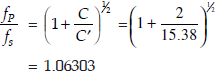
fp exceeds fs by more than 6.303%.
11.1 In the Hartley oscillator, L2 = 0.04 mH and c = 0.004 μF. If the frequency of the oscillator is 150 KHz, find L1. Neglect mutual inductance.
11.2 In a Colpitts oscillator, C1 = 0.2 μF and C2 = 0.04 μF. If the frequency of oscillation is 10 KHz, find the value of Inductor. Also, find the required gain for oscillation.
11.3 In an RC phase-shift oscillator R = 200 KΩ and C = 200 pF. Find the frequency of the oscillator (a) BJT (b) for FET.
11.4 In wien-bridge oscillator R = 200 KΩ and f = 10 KHz. Find the value of C.
11.5 A crystal has the following parameters L = 0.1 h, C= 0.05 pF, C′ = 2 pF and R = 5 K. Find series and parallel resonances frequency and Q-factor of the crystal.
11.6 A Colpitts oscillator is designed with C1 = 100 pF and C1 = 7500 pF. Find the range of inductance values if the frequency of oscillation vary between 950 and 2050 KHz.
11.7 A tuned collector oscillator in a radio receiver has a fixed inductance of 60 μh and has to be tunable over the frequency band of 500 to 1500 KHz. Find the range of variable capacitor to be used.
11.8
- Find
 for the circuit shown.
 - Find the expression for the frequency of oscillation.
- Find the minimum gain required for oscillation.

11.9 A MOSFET with μ = 60 and rd = 4 K is used in a phase-shift oscillator.
- Find the minimum value of the Rd for which the circuit will oscillate.
- Find the product RC.
11.10
- For the Hartley oscillator shown, find the frequency of oscillation.
- Find the vlaue of Rs for which the value of loop gain will adjust equal unity.

- State and explain the Barkhausen criterion for oscillations in a sinusoidal oscillator with feedback network.
- Draw the circuit diagram of a RC phase-shift oscillator employing FET and derive the equation for the frequency of oscillation and condition of oscillation.
- Draw the circuit diagram of a RC phase-shift oscillator employing BJT and derive the equation for the frequency of oscillation and condition of oscillation. Why is voltage shunt configuration employed in such a circuit?
- What is resonant circuit oscillator? Draw its circuit employing FET and derive the condition and frequency of oscillation of the circuit.
- Discuss the advantages and limitations of a resonant circuit sinusoidal oscillator.
- Enumerate the advantages and applications of a RC phase-shift oscillator.
- Discuss why Barkhausen criterion is only applicable to a sinusoidal oscillator. Also, give the practical limitation of applying Barkhausen criterion to the sinusoidal oscillator and how this is overcome.
- Derive the equations for condition of oscillation and frequency of oscillation for a general format of positive feedback oscillator.
- Draw the circuit of a Colpitt oscillator and give its applications.
- Derive the frequency of oscillation and condition of oscillation of a Hartley oscillator and give its applications and limitations.
- Enumerate the applications of a Wein bridge oscillator and derive the expression frequency of oscillation of the circuit.
- Discuss about the amplitude stability of a sinusoidal oscillator and give a circuit that has maximum stability.
- What oscillator is employed if very stable frequency oscillations are required? Why?
- What is piezoelectric effect? What materials exhibit such effect? How is this effect useful in sinusoidal oscillators?
- Draw the frequency response of a quartz crystal and give the expressions for resonant frequencies. Also, indicate the electronic symbol and electric equivalent circuit of such a crystal.
- Discuss at length the frequency stability of sinusoidal oscillators. A crystal oscillator has the highest frequency stability. Justify.
- Discuss the applications and limitations of a crystal oscillator.
- What is a Clapp oscillator? Enumerate the advantages of this over the Colpitt or Hartley oscillators.
- Draw the circuit of a Wein bridge oscillator using Op-Amp. Derive an equation for the condition of oscillation of a Wein bridge oscillator.
- Draw the circuit diagram of a sinusoidal oscillator, which employs RF transformer for feedback using a BJT, and derive the equation for frequency of oscillation.
- State the frequency stability criterion for sinusoidal oscillators.
- Draw the electric model of a quartz crystal. Over which portion of the curve reactance curve the oscillations are possible?
- Draw the circuit diagram of a crystal oscillator and explain its operation in detail.
- What determines the frequency of oscillations in a Wien bridge oscillator?
- Sketch the circuit of a tuned collector oscillator and explain its operation. Give the condition for oscillation and frequency of oscillation.