
Chapter 14
Cathode-ray Oscilloscope

Basic construction of a CRT
Chapter Outline
The concepts introduced in this chapter are:
- The force on motion of electron in magnetic field
- The electron path when subjected to magnetic fields
- The behaviour of electron when subjected to both electric and magnetic fields
- Types of deflections of an electron beam
- Different methods of focusing electrons to a fine spot in an electron beam
- Constructional features of a CRT
- Applications of CRO
14.1 INTRODUCTION
The signals employed in electronic circuits may be audio, video, data, timing signals and so on. Generation and manipulation are the main functions of electronic circuits. To manipulate the generated signal, one requires measurement of various parameters of the signal. The electric signal may be dc or ac voltage or current. There are various meters that can measure the parameters of the signals. These meters give the values of the parameters under some assumed conditions. For example, when measuring the rms value of ac signal, the assumption is that the signal is pure sinusoid. The measurement would be wrong if there is any deviation in the shape of the signal under measurement and also no other form of ac signal can be measured with this device. These problems of measurement can be solved when the signal is displayed in its exact form. This is achieved with the help of cathode-ray oscilloscope (CRO).
The CRO provides a visual presentation of any wave form applied to the input terminals. The heart of CRO is the cathode-ray tube (CRT), which provides the display giving the form of the signal applied on the screen. An electron beam is deflected as it sweeps across the tube face, leaving a display of the signal applied to the input terminals. A wide range of CROs are available depending on the signal parameter requirements. A CRO may be built to operate from few hertz up to hundreds of megahertz. A CRO also measures time from fractions of nanoseconds to many seconds.
The CRT consists of the following basic parts:
- An electron gun to produce a stream of electrons
- Focusing and accelerating elements to produce a well-defined beam of electrons
- Horizontal and vertical deflecting plates to control the path of the electron beam
- An evacuated glass chamber with a phosphorescent screen, which glows visibly when stuck by the electron beam.
The following sections of this chapter present the analysis of electron motion in electrostatic and electromagnetic deflection as well as focusing, and finally the applications of the CRO are discussed.
14.2 TWO-DIMENSIONAL MOTION OF ELECTRON
The force on a unit positive charge at any point in an electric field is defined as electric-field intensity ε at that point. Thus, the resulting force on the positive charge q is in the direction of field intensity and is given by
To determine the path of the charged particle in the electric field, by Newton’s second law,
where a is acceleration, v is the velocity and m is the mass. When the charged particle is electron, q = − e, where e is the charge in coulombs on an electron.
Consider a parallel-plate capacitor as shown in Fig. 14.1. When distance between the plates is much small compared to the area of the plates, the field between the plates can be assumed to be uniform and lines of force pointing in the negative x direction. That is, there is only one field in the − x axis. Since there is no force in the y and z directions, acceleration along these directions must be zero. Thus, the only possible direction of electron movement is along x axis. From Eq. (14.2),

or,
The velocity and displacement can be given as follows, provided the acceleration in x direction ax is constant and independent of time as
and,
are acceleration and velocity, respectively.
Now, consider a uniform field; εx may be a function of distance but is independent of time, from Eq. (14.2),
Multiplying the above equation with dx = vx dt and integrating,
The potential V of a point x with respect to point xo is work done against the field in taking a unit positive charge from xo to x. Thus,
Equation (14.7) can be written as
If A and B are two points with B at higher potential than A, VBA is the potential difference and q is the charge in coulombs, then,
The above equation is not valid if the field varies with time. If an electron starts at rest and VBA = V, vA=0, vB = v, its final speed v can be given as
v = [2eV/m]1/2 …(14.11)
= 5.93 × 10⁵ V1/2 …(14.12)
This equation is valid only when an electron starts from rest. If it possesses some initial velocity, Eq. (14.10) is to be used. So, if an electron falls in a field of 1 V starting at rest, the final velocity achieved by it is 593 km/s. Even though the velocity is very large, the associated kinetic energy is very small compared with that of an electron due to minute mass associated with it.
Two-dimensional motion: The following assumptions are made in the following analysis:
- The charge density is low enough so that the mutual repulsive force may be neglected.
- The movement of the charged particle is in high vacuum so that no collision with gas atoms or ions occurs.
- The mass of the charged particle is extremely small so that the gravitational force may be neglected as compared to the forces exerted by the fields.
Consider a situation as depicted in Fig. 14.2 where an electron enters the region between two parallel plates of a parallel-plate capacitor with an initial velocity vox in the positive x direction. Assuming the electric field to be uniform and directed in negative y direction, the initial conditions are

Fig. 14.2 Two-dimensional motion in a uniform electric field
vy = 0 at y = 0, t = 0 …(14.13)
vz = 0 at z = 0, t = 0
Thus, the component of velocity in the z direction remains constant since there is no force in the z direction and thus acceleration is zero. Since the initial velocity in this direction is assumed to be zero, the motion must take place entirely in one plane, the plane of the paper.
Similarly, the velocity along x axis remains constant and equal to vox. Thus,
Then,
A constant acceleration exists along the y direction and the motion is given by Eq. (14.4) with x replaced by y,
where,
where V = Vd. These equations indicate that in the region between the plates the electron is accelerated upward, the velocity component vy varying from point to point, whereas the component vx remains constant in the passage of electron between the plates. Eliminating t from Eqs. (14.15 and 14.16),
Thus, the particle moves in a parabolic path in the region between the plates.
14.3 FORCE AND MOTION IN MAGNETIC FIELD
The force acting on a conductor of length L carrying a current I situated in a magnetic field B is given by
The direction of force is perpendicular to the plane consisting of the components of B and I that are mutually perpendicular and is directed along the advance of a right-hand screw as shown in Fig. 14.3.
If an electron takes T seconds to travel a distance of L metres in the conductor, the total number of electrons passing through any cross-section of conductor in unit time is NT, where N is the total number of electrons contained in the conductor. Thus, the total charge per second crossing any point is
I = Nq/T …(14.20)
fm = BIL = BNqL/T …(14.21)

where v is the drift velocity and the force per electron is
If the particle is a positive ion, the directions of current and velocity are same. If the particle is an electron, the direction of the current is opposite to that of the drift velocity. Motion in a magnetic field: The path of a charged particle that is moving in a magnetic field is now investigated. Consider an electron to be placed in the region of the magnetic field. If the particle is at rest, fm = 0 and the particle remains at rest. If the initial velocity of the particle is along the lines of the magnetic flux, there is no force on the particle. Hence, a particle whose initial velocity has no component normal to a uniform magnetic field will continue to move with constant speed along the lines of flux.
Now, assume that an electron moving with a speed vo enters a constant uniform magnetic field normally as shown in Fig. 14.4. Since the force fm is perpendicular to v and so to the motion at every instant, no work is done on the electron. That is, the kinetic energy is not increased. Since v and B are both constant in magnitude, fm is constant in magnitude and perpendicular to the direction of motion of the particle. This type of force results in motion in a circular path with constant speed. The force remains constant in magnitude and is always directed toward the centre of the circle and so is normal to the motion.
A particle moving in a circular path with constant speed v has an acceleration toward the centre of the circle of magnitude v2/R, where R is the radius of the path. Thus,
or
Angular velocity can be given as

The period, time in seconds, for one complete revolution can be derived to be
For an electron, it is
It can be observed that the radius of the path is directly proportional to the speed of the particle. Further, the period and the angular velocity are independent of speed or radius. That is, the faster moving particles will traverse larger circles in the same time that a slower particle moves in its smaller circle.
14.4 PARALLEL ELECTRIC AND MAGNETIC FIELDS
When electric and magnetic fields act simultaneously on an electron, whether they are in same or opposite directions and whether the initial velocity is zero or not, no force is exerted due to magnetic field and the motion of the electron is only due to the electric field. The electron will move in a direction parallel to the fields with constant acceleration. If the electric field is directed in positive y direction whereas the magnetic field in the negative y direction, the complete motion of the electron can be given as
where a = eε/m is the magnitude of acceleration. The negative sign in these equations is due to the fact that the direction of the acceleration of an electron is opposite to the direction of the electric field ε.
If initially a component of velocity vox perpendicular to the magnetic field exists, this component along with the magnetic field will set the electron in a circular motion. The radius of the circular path is independent of the electric field, but the velocity along the field changes with time. As a result of this, the electron travels in a helical path with the pitch changing with time. The distance travelled along y axis per revolution increases with each revolution.
14.5 PERPENDICULAR ELECTRIC AND MAGNETIC FIELDS
If the magnetic field is along the negative y direction and the electric field is along negative x direction and the electron is starting from rest at the origin, the force on the electron due to the electric field is directed along the positive z direction. Any force due to the magnetic field is always normal to B and hence lies in a plane parallel to the x-z plane. Thus, there is no component of force along the y direction and the y component of acceleration is zero. Hence, assuming the electron starts at origin, the motion along y is given by
If the initial velocity component parallel to B is zero, the path lies entirely in a plane perpendicular to B. Since the initial velocity is zero, the initial magnetic force is zero and due to the electric field the electron is directed along the positive x axis. As the electron is accelerated in positive x direction, the force due to the magnetic field is no longer zero. There will be a component of this force, which is proportional to the x component of velocity and will be directed along the positive z direction. The path will thus bend away from the positive x direction towards the positive z direction. The electric and magnetic fields interact with each other and the net force will finally make the electron travel in a cycloidal path. A cycloid is defined as the path generated by a point on the circumference of a circle of given radius, which rolls along a straight line.
When an electron is released perpendicular to both the electric and magnetic fields, so that vox = voy = 0 and voz ≠ 0, the electric force is along positive x direction and the magnetic field is along negative x direction. If the net force on the electron is zero, it will continue to move along z axis with the constant speed voz. Thus, the electron follows a straight-line path. This condition is realised when
Thus, when an electron is released with the above velocity into perpendicular electric and magnetic fields, it suffers no deflection and the net force on it is zero. It may be noted that this velocity is independent of charge or mass of the particle.
If the initial velocity component in the direction perpendicular to the magnetic field is not zero, the path of the electron is trochoid. Trochoid is the locus of a point on a spoke of a wheel rolling on a straight line.
14.5 ELECTROSTATIC DEFLECTION
The deflection system adopted in a cathode-ray tube can be electrostatic deflection. It consists of a pair of deflection plates as shown in Fig. 14.5. The deflection voltages are applied between the two plates. For deflecting the beam in the horizontal and vertical directions, two sets of plates are required. The horizontal deflection plates are placed vertically and the vertical deflection plates are placed horizontally. The plane of the plates is always parallel to the axis of the cathode-ray tube. The electrons are attracted towards the positive plates and when they leave the region below the plates they travel in a straight line, at an angle with the axis. These electrons, which leave the region, strike the screen at a point.

The hot cathode K emits electrons, which are accelerated toward the anode by the applied potential. Those electrons, which are not collected by the anode, pass through the tiny hole in the anode and strike the fluorescent screen. The electrons striking the screen emit energy in form of photons and thus light is emitted from the screen. The displacement D of the electrons is determined by the potential Vd applied between the deflecting plates. The velocity with which the electrons emerge from the anode hole can be given as
assuming the velocity of electron emission from cathode to be zero. Since the region between the anode and the edge of the deflection plates is field free, the electrons move in a straight line and with constant velocity. In the region between the plates, the electrons will move in the parabolic path given by Eq. (14.18). The straight-line path in the region from emerging point M of the plates to the point P′ on the screen is the tangent to the parabola at the point M.
The deflection D from the axis of the tube can thus be estimated to be
Thus, the deflection on the screen of a CRT is directly proportional to the deflecting voltage applied between the plates. Consequently, a CRT is a linear voltage-indicating device.
The electrostatic deflection sensitivity of a CRT is defined as the deflection on the screen per volt of the deflection voltage. Thus,
The sensitivity is independent of both the deflecting voltage and the ratio e/m. Further, he sensitivity varies inversely with accelerating voltage.
The assumptions made in this connection that the deflection field is uniform and the region outside the deflecting plates is field-free may not be possible in practice. This leads to the fringing fields and correction is to be employed up to as much as 40% of the aboveachieved result.
14.6 MAGNETIC DEFLECTION
It may be seen that in order to achieve deflection of the electron beam in a CRT, magnetic as well as electric fields may be employed. Since it is not feasible to use extending over the entire length of the tube, a short coil furnishing a transverse field in a limited region is employed as shown in Fig. 14.6.

Fig. 14.6 Magnetic deflection system
The magnetic field is taken as pointing out of the paper and the beam is deflected upwards. It is also assumed that the magnetic field is uniform in the restricted region and the region outside is field-free. The emerging electron beam experiences a force of magnitude eBv in the region of magnetic field. The path OM will be an arc of a circle whose centre is at Q. The speed of the electrons will remain constant and equal to
The angle φ is is equal to the length of the arc OM divided by R, the radius of the circle. If φ is small,
where
The deflection D on the screen can be derived to be

The sensitivity of magnetic deflection can be defined as the ratio of deflection to the magnetic field intensity. Thus,
Thus, the sensitivity is independent of B. In electrostatic deflection, the sensitivity is independent of anode voltage but in magnetic deflection, it is inversely proportional to the root of anode voltage. Also, this sensitivity depends on the ratio e/m. Since the sensitivity is proportional to L, the deflecting coils are to be placed as far as possible from the screen. In general, they are placed directly after the accelerating anode.
In a TV, the deflection angle is large and so the assumptions made in the above discussion are not valid. So, the deflection is no longer proportional to B and so the deflection of the beam on the face of the tube will not be linear with time. In a TV, there are two sets of deflection coils mounted on the neck of the tube to achieve horizontal and vertical deflection of the electron beam.
14.7 ELECTROSTATIC FOCUSING
The convergent beam from the accelerating electrode has a tendency to spread because of the mutual repulsion between the electrons. Hence, some focusing device is required to bring the beam to a sharp focus at the screen. There are two methods of focusing. They are electrostatic and magnetic.
In electrostatic focusing, the electron lens system formed between electrodes makes the electron beam focus into a fine spot on the screen. Both these electrodes are anodes and are at high voltage compared to that of the cathode.
Usually, the electron gun contains two electrostatic focusing systems referred to as electron lenses. The first electron lens comprises the cathode, control grid, and the first accelerating electrode. The dimensions of the electrodes and their voltages are so chosen that the electrons emitted from the cathode converge to a small area located in front of the cathode and on the axis of the tube. This crossover surface has an area much smaller than that of cathode and may be treated as the source of electrons for all electrodes beyond this point. Figure 14.7 shows the nature of equipotential contours thus produced. Electrons move normal to these contours.
The second electron lens system is formed in the region between accelerator electrode and the first anode. Figure 14.8 shows the equipotential contours of such a system. The electrons move perpendicular to these contours. The shape of the contours depends on the geometry of the electrode system. The electric-field magnitude depends on the potentials applied to the electrodes.
Usually, the second voltage and accelerating electrode voltage are maintained constant while the first anode voltage is varied to achieve the necessary focusing. The size of the focused spot on the florescent screen depends on the size of the crossover and the magnification of the second lens system. The magnification is generally much less than unity. To reduce the dimension of focused spot, the apertures in the gun may be made small, thus eliminating divergent electrons. The mutual repulsion of electrons within the cathode-ray beam and unequal velocities of emitted electrons limit the minimum size of spot.


Fig. 14.8 The second electron lens system
The purpose of the control electrode in the first lens of the electron gun is to vary the current in the beam. However, change in control electrode voltage also changes to some extent the focal length of the first lens, thus changing the size of the focused image on the screen.
14.9 MAGNETIC FOCUSING
Magnetic focusing may be achieved either by a permanent magnet or by an electromagnetic coil, whose axis coincides with the axis of the beam. The coil may extend the whole length of the electron beam or may be limited to a small region. Extended coil is employed in image orthicon camera tube of a TV and short coil type is employed in TV receivers, radar indicators and general purpose CRO.

The principle of magnetic focusing is as shown in Fig. 14.9. The focusing coil surrounds the tube. The lines of magnetic field are uniformly distributed and are parallel to the direction of the electron motion.
The electron experiences a force from the magnetic field only if its motion is at an angle to the lines of magnetic force. If the line of motion and magnetic lines of force are parallel, the electron moves only by the attractive force of the anode. If the electron leaves the cathode at an angle to the axis of the system, a force is exerted on it by the magnetic field. The direction of this force is at right angle to the direction of motion of electron and to magnetic line of force. The force thus causes the electron to move in a spiral path. If this circle is just completed by the time the electron reaches the screen, the electron must lie on the axis of the tube just opposite the point where it was emitted at the last aperture of the gun. All the electrons emerging from a point are brought to a corresponding point on the screen.
In general, the electrons emitted from the cathode have different initial velocities and varying angles to the axis of the tube. The time required by the electron to complete one circle of the spiral flight depends on the strength of the magnetic field and on the charge to mass ratio of the electron. Since the ratio of the charge to mass of electrons is same for all the electrons and also in a uniform magnetic field, all the electrons complete one circle in same time.
The magnitude of the magnetic field depends on the current flowing in the coil and also number of turns of the coil. The magnitude of the field is adjusted by controlling the current until a perfect focusing on the screen is achieved.
14.10 CATHODE-RAY TUBE
The cathode-ray tube (CRT) is the heart of the cathode-ray oscilloscope (CRO). CRT provides the visual display of the input signal wave form. Figure 14.10 shows the basic construction of the CRT.
A cathode K containing an oxide coating is heated indirectly by a filament, which results in the release of electrons from the cathode surface. A control grid G provides control of the number of electrons passing through the aperture into the tube. The number of electrons to be emitted to the tube is controlled by the voltage of the control grid.

After the electrons pass the control grid, they are focused into a tight beam and accelerated to a higher velocity by the focusing and accelerating anodes.
The high-velocity well-defined electron beam then passes through the two sets of deflection plates. The first set of plates is oriented to deflect the electron beam vertically up or down. The direction of vertical deflection is determined by the voltage polarity applied to the deflecting plates. The amount of deflection is set by the magnitude of the applied voltage. The beam is also deflected horizontally left to right by a voltage applied to the horizontal deflecting plates. The deflected beam is further accelerated by very high voltages applied to the tube, with the beam finally striking a phosphorescent material on the inside face of the tube. This screen glows when struck by the high-speed electrons. Thus, light is emitted on the other side of the glass screen.
The CRT is a self-contained unit with leads brought out through a base to pins. Various types of CRTs are available in a variety of sizes and with different phosphor screens and deflection electrodes. CRTs find many applications in CRO, TV, radar indicators and so on, of which CRT for CRO is considered in this section.
In a CRO, the electron beam is deflected horizontally by a sweep voltage and vertically by the voltage to be measured. While the electron beam is moved across the face of the CRT by the horizontal sweep signal, the input signal deflects the beam vertically, resulting in a display of the input signal wave form. One sweep of the beam across the face of the tube, followed by a blank period during which the beam is turned off while returned to the starting point across the tube face, constitutes one sweep of the beam.
The display on the screen will be steady when the same image is swept across the tube in each sweep. This requires synchronisation, starting the sweep at the same point in a repetitive wave form cycle. If the signal is properly synchronised, the display will be stationary. If the synchronisation is not proper, the image will drift in horizontal direction.
Figure 14.11(a) shows a basic block diagram of a CRO. To achieve a noticeable deflection on the screen of the CRO, the measured voltage, which is of the order of millivolts to tens of volts, must be increased to order of hundreds of volts for proper operation of the CRO. Amplifiers are adopted for this purpose in both vertical and horizontal deflection systems. To adjust the amplitude of the signal for comfortable display measurements on the screen, the input is subjected to variable attenuation.

A sawtooth wave form is impressed across the horizontal deflection plates. This voltage, as shown in Fig. 14.11(b) is used to sweep the beam across the screen. Thus, it is also known as sweep voltage. The electrons are deflected with time in the horizontal direction for a time T. Then, the beam returns to its starting point on the screen very quickly as the sawtooth voltage rapidly falls to its initial value at the end of each period.
If a sinusoidal voltage is impressed across the vertical deflection plates and no sweep is applied to horizontal deflection plates, the display on the screen would be a vertical straight line. Now, when the sweep voltage is applied to horizontal deflection plates, the electron beam sweeps the electron beam across the screen in time and the full sinusoidal voltage is displayed on the CRT screen. The display would be stationary only when the sweep and input signals are properly synchronised. This is achieved when the time period T of the sweep be equal to or is multiple times of the time period T. Thus, it is required to adjust the sweep period of the sawtooth wave form to synchronise with the applied input signal time period.
The input signal can be any wave form. Thus, when a nonrepeating arbitrary wave form is to be displayed on the screen, the transients are taken as the reference and the sweep would start with the start of the transients.
A commercial oscilloscope has many refinements than those discussed above. The sensitivity is greatly increased by means of amplifiers between the input signal and the deflection plates. The electron gun is a complicated structure, which allows for accelerating the electrons through a large potential, for varying the intensity of the beam and for focusing the electrons into a tiny spot. Controls are provided for positioning the beam as desired on the screen.
14.11 APPLICATIONS OF CATHODE-RAY OSCILLOSCOPE
CRO is a very versatile instrument that is used for a variety of applications. Some of these applications are as follows:
- Observation of wave forms: CROs are mainly used to observe wave forms. Ordinary CROs are normally capable of operation in tens of megahertz range. Special purpose CROs are available that can operate in gigahertz range. In storage oscilloscopes, the signal can be stored and retrieved as and when required.
- Measurement of voltage: CROs are voltage-dependent instruments and can be used for the measurement of voltages at any frequency within the range of the operation of the CRO. To measure voltages, the input voltage is applied on the vertical deflection plates and appropriate sweep to the horizontal deflection plates. The amplitude trace of the wave form is then observed on the screen. The amplitude attenuator is then adjusted such that the signal is displayed comfortably on the screen. The position of the attenuator knob gives the volts/cm position and thus the voltage of the input signal can be measured by multiplying this position value with the number of centimetres the signal is occupying in the vertical direction. Either ac or dc voltages can be measured. The dc voltages are displayed as horizontal straight line whereas the exact wave form is displayed for that of ac signal. From the peak value of the ac signal, the rms and other parameters can be determined. Not only can perfect sinusoidal wave forms be measured, but since the wave form is displayed, the amount of distortion and other parameters of interest can also be determined.
- Measurement of current: Current cannot be directly measured with a CRO. To measure the current, a known resistance is taken and the potential drop across the resistance is determined with the help of measurement of potential at both ends of the resistor. This voltage difference divided by the considered resistance value gives the amount of current flowing in the device.
- Measurement of frequency: The measurement of frequency is indirect with a CRO. The time period of the input signal is determined with the help of the CRO and the frequency of the input signal is the reciprocal of this time period. The signal whose frequency is to be measured is applied as usual to the vertical deflection plates of the CRT along with the sweep voltage to horizontal deflection plates. The amplitude and the time attenuation knobs are appropriately adjusted such that the signal is displayed comfortably on the screen of the CRO. The time duration between two identical points along the wave form is the time period of the input signal wave form. This is measured by multiplying the time/cm value of time attenuator knob with the distance in cm between two consecutive identical points on the wave form on the screen of the CRO. The reciprocal of this time period is nothing but the frequency of the input signal wave form.
- Lissajous figures: Lissajous figures are geometrical figures obtained as a result of the compounding of two simple harmonic wave forms. The two wave forms are applied to the vertical and horizontal deflection plates of the CRO, respectively; it will represent a set of figures called Lissajous figures. With the help of these figures, one can determine the ratio of the amplitudes of the signals when the frequency is identical and the two signals are in phase, determine the phase difference between the two signals of same frequency or determine the unknown frequency of a given signal when the frequency of the other signal is known. If vx and vy represent these two wave forms, when vx = Vx sin ωt and vy = Vy sin ωt, the trace of the electron beam on the screen of the CRO would be a straight line with slope equal to Vx/Vy as shown in Fig. 14.12.
When vx = Vx sin ωt and vy = Vy cos ωt, and when Vx = Vy, the trace of the electron beam on the screen would be a circle and when Vx ≠ Vy, the trace would be an ellipse as shown in Fig. 14.13.
When vx = Vx sin ωxt and vy = Vy sin (ωyt + θ), where θ is the phase angle between the two signals, the trace of the electron beam on the screen would be complex and is as shown in Fig. 14.14. One can determine frequency of an unknown wave form when the other signal frequency is known. The unknown frequency can thus be measured with the following equation:


Fig. 14.12 Lissajous figure for two identical signals

Fig. 14.13 Lissajous figure for two signals, which are out of phase

SUMMARY
- A cathode-ray oscilloscope has the basic device of displaying the signal wave form as the cathode-ray tube.
- Cathode-ray tube has an electron gun, which emits electrons from a cathode.
- The electrons emitted from the cathode of the gun are accelerated and focused into a fine spot by either electrostatic field or magnetic field.
- To display the wave form on the screen, the electron beam is to be deflected from left to right and top to bottom. This deflection can either be electric or magnetic.
- CRT finds many applications—CRO, TV, radar displays and so on.
- In CRO, the vertical deflection of the electron beam is by the applied input signal whereas the horizontal deflection is by sweep signal wave form, which is a sawtooth wave form.
- In a CRO, the focusing is by electrostatic field and the deflection is by magnetic field.
- The charge particle path between parallel plates is parabolic.
- The motion of an electron in a magnetic field is circular with constant speed.
- When electric and magnetic fields, which are parallel, are applied on a moving electron and when the initial velocity is perpendicular to magnetic field, the path of the electron is helical with pitch changing with time.
- When an electron is subjected to simultaneous electric and magnetic fields, which are perpendicular to each other, the path of the electron is cycloid.
- The deflection sensitivity of electrostatic deflection is independent of both the deflecting voltage and the ratio e/m and varies inversely with accelerating voltage.
- The deflection sensitivity of magnetic deflection is independent of magnetic field, is inversely proportional to the root of anode voltage and depends on the ratio e/m.
- The electron lens system formed between the electrode systems is utilised for focusing the electron beam in electrostatic focusing.
- The deflection coils are mounted at the neck or throughout the length of the CRT for focusing the beam in magnetic focusing.
- The various applications of CRO are measurement of voltage, current, frequency, phase, distortion and so on, whether the input signal is ac or dc.
SOLVED PROBLEMS
14.1 Find the speed and kinetic energy of an electron after it has been accelerated through a potential difference of 1000 V.
Solution Speed of an electron

Kinetic energy K.E. |
= |
q × V |
|
= |
1.6 × 10−19 × 1000 |
|
= |
1.6 × 10⁻¹⁶ Joules |
|
= |
1000 eV |
14.2 A charged particle, having mass equal to 1000 times of an electron and a charge same as that of an electron is accelerated through a potential difference of 1000 V. Calculate the velocity attained and the kinetic energy in eV and Joules.
Solution Mass of charged particle = 1000 × 9.1 × 10−31 kg
= 9.1 × 10⁻²⁸ kg
Charge = 1.6 × 10⁻¹⁹ C

Kinetic energy |
= |
q × V |
|
= |
1.6 × 10−19 × 1000 |
|
= |
1.6 × 10⁻¹⁶ joules |
|
= |
1000 eV |
14.3 Two plane parallel plates A and B are placed 5 mm apart and potential B is made 300 V positive with respect to plate A. An electron starts from rest from plate A. Calculate (a) the velocity of the electron on reaching plate B (b) time taken for the electron to reach plate B (c) kinetic energy of the electron on reaching plate B.
Solution
- The electron starts from rest at plate A, so, the initial velocity is zero. The velocity of electron on reacting plate B is
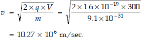
- The average velocity of electron

Therefore, time taken for travel is

- Kinetic energy of the electron on reaching plate B is
KE = q · V = 1.6 × 10−19 × 300
= 4.8 × 10⁻¹⁷ Joules
14.4 In a vacuum diode, the spacing between the parallel plane plates of cathode and anode is 5 mm, and the potential difference is 250 V. Calculate the time taken by the electron, with an initial velocity of 1 × 10⁶ m/sec, to travel from cathode to anode.
Solution V = 250 V, d = 5 × 10⁻³ m, vinitial = 1 × 10 6 m/s
∴ The speed acquired by the electron due to the applied voltage is

time taken to travel from cathode to anode ![]()
14.5 An electron enters a uniform magnetic field of flux density 10−6 Wb/m2 with a velocity of 108 m/sec, normal to the field. Calculate the radius of the circular path that the electron will trace.
Solution

14.6 An electrostatic cathode ray tube has a final anode voltage of 400 V. The deflection plates are 2 cm long and 1 cm apart. The screen is at a distance of 10 cm from the centre of the plates. A voltage of 20 V is applied to the deflection plates. Calculate (a) the velocity of the electron on reaching the field (b) acceleration due to deflection field (c) deflection produced on the screen and (d) deflection sensitivity.
Solution
- V = 600 V, l = 2 cm, d = 1 cm, L = 10 cm Vd = 20 V

- ma = qε

- Deflection on the screen,


- Deflection sensitivity

14.7 In a cathode ray tube having electric deflection system, the deflection plates are 2 cm long and have a uniform spacing of 4 mm between them. The fluorescent screen is 25 cm away from the centre of the deflection plates. Calculate the deflection sensitivity, if the potential of the final anode is (a) 1000 V (b) 2000 V (c) 3500 V.
Solution d = 4 mm, l = 2 cm, L = 25 cm,
Deflection on the screen ![]()

- When V = 2000 V
S = 0.3125 × 10⁻³ cm/V
- When V = 3500 V

14.8 In a CRT, the distance of the screen from the centre of the magnetic field is 22 cm. The deflection magnetic field of flux density 2 × 10⁻⁴ Wb/m2 extends for a length of 2.5 cm along the tube axis. The final anode voltage is 1250 V. Find the deflection of the spot in cm.
Solution L = 22 × 10−2 m, B = 2 × 10⁻⁴ Wb/m2, l = 2.5 × 10⁻² m, V = 1250 V
The deflection of the spot

14.9 The electron beam in a CRT is displaced vertically by a magnetic field of flux density 10−4 Wb/m2. The length of the magnetic field along the tube axis is same as that of the electrostatic deflection plates. The final anode voltage is 450 V. Calculate the voltage which should be applied to the ϒ-deflection plates 0.6 cm apart, to return the spot back to the centre of the screen.
Solution The magnetostatic deflection ![]()
The electrostatic deflection ![]()
For returning the beam to the centre, the electrostatic deflection and the magnetostatic deflection must be equal.

given V = 450, B = 10−4 Wb/m2, d = 0.6 × 10⁻² m

14.10
- If the voltage Vm1 cos ωt and Vm2 sin ωt are applied respectively to the horizontal and vertical deflecting plates of an oscilloscope, prove that the electron beam will trace an ellipse on the screen.
- A sine wave voltage is displayed on a CRO. Its vertical amplifier sensitivity is set at 5 V/cm and the time base selector swith is set at a sweep speed of 50 μ/cm. The displayed sine wave has peak-to-peak amplitude of 5.4 cm and its 4 complete cycles are accommodated over 8.4 cm of horizontal axis. Find the rms value and the frequency of the input voltage.
Solution

Squaring and adding, we get

Hence proved.

14.11 Two sinusoidal voltage signals of equal frequency are applied to the vertical and horizontal deflection plates of CRO. Find the phase angle of each trace.

- Phase angle
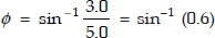 = 36.9° or 143.1°.
 - Phase angle
 = 30° or 150°.
14.12
- Find the ratio of frequencies of vertical and horizontal signals for a Lissajous pattern shown below.

- Find the frequency of vertical signal if the frequency of horizontal signal is 3 kHz.

- A Lissajous pattern on an oscilloscope is stationary and has 5 horizontal tangencies and 2 vertical tangencies. The frequency of horizontal input is 1000 Hz. Determine the frequency of vertical input.
Solution
- From the Lissajous figure
Positive X-peaks = 2

- Positive ϒ-peaks in pattern = 2 + 1/2 = 2)½
Positive X-peaks in pattern = 1/2 + 1/2 = 1

fy = 3 K × 2½ = 7.5 kHz
- fx = 1000 Hz
Points of tangency to vertical line = 2
Points of tangency to horizontal line = 5

EXERCISE PROBLEMS
14.1 Find the speed and kinetic energy of an electron after it has moved through a potential difference of 5000 V. (Ans: 4.2 × 10⁷ m/s, 5000 eV)
14.2 Two plane parallel plates A and B are placed 3 mm apart and potential of B is made 200 V positive with respect to plate A. An electron starts from rest from plate A. Calculate (a) the velocity of the electron on reaching plate B. (b) time taken by the electron to travel from plate A to plate B. (c) Kinetic energy of the electron on reaching the plate B. (Ans: 8.38 × 10⁶ m/s, 0.71 ns, 3.2 × 10⁻¹⁷ J)
14.3 Two plane parallel plates A and B are placed 8 mm apart and plate B is 300 V more positive than plate A. The electron travels from plate A to plate B with an initial velocity of 1 × 10⁶ m/sec, calculate the time of travel. (Ans: 1.4 ns)
14.4 In a CRT, the distance of the screen from the centre of the magnetic field is 20 cm. The deflecting magnetic field of flux density 1 × 10⁻⁴ Wb/m2 extends for a length of 2 cm along the tube axis. The final anode voltage is 800 V. Find the deflection of the spot. (Ans: 0.42 cm)
14.5 A CRT is designed to have a deflection sensitivity of 0.3 mm per volt. The plates are required to be 3 cm long and 0.6 cm apart. The distance of the screen from centre of plates is to be 20 cm. What should be the final anode voltage? (Ans: 3333 V)
14.6 The voltage across horizontal deflection plates of a CRO is V1 sin (ωt + θ1) and that across the vertical deflection plates is V2 sin (ωt + θ2). Prove that the trace on the screen is an ellipse.
14.7 Voltage V1 is applied to the horizontal input and voltage V2 is applied to the vertical input of the CRO. V1 and V2 are having the same frequency. The trace is an ellipse. The slope of the major axis is positive. The maximum vertical value is 2.5 divisions and the point where the ellipse crosses the vertical axis is 1.25 divisions. The ellipse is symmetrical about the horizontal and vertical axis. Determine the possible phase angles of V2 with respect to V1.
- Give the construction of CRT using electrostatic focusing and deflection systems and describe functions of each in detail.
- Describe the method of electrostatic focusing in a CRT.
- Describe the focusing action in a CRT using magnetic focusing.
- What is the path of an electron entering a uniform magnetic field obliquely?
- Derive the equation for electrostatic deflection sensitivity.
- Prove that the electron beam in a CRT appears to emerge from a point at the centre of the electrostatic deflection system.
- Derive the expression for deflection sensitivity of CRT in a magnetic deflection system.
- What is the function of time base voltage in a CRO?
- Draw a basic block diagram of a CRO and explain the features of CRO in detail.
- What are the applications of a CRO? Explain any two of them in detail.
- How do you measure frequency of an unknown signal using CRO? Explain.
- What are Lissajous figures? How do you measure phase between two signals with the help of these figures?
- Discuss the two-dimensional motion of an electron in a parallel-plate capacitor.
- Discuss the force experienced by an electron in a magnetic field.
- Prove that the path of an electron in a magnetic field is circular.
- Determine the path of the electron when subjected to electric and magnetic fields, which are parallel to each other.
- Discuss the behaviour of the electron when electric and magnetic fields are applied and when they are perpendicular to each other.
- How many types of deflection systems are possible in a CRT? Discuss them in detail.
- Compare the electrostatic and magnetic deflection in terms of deflection sensitivity.
- How is focusing of electron beam achieved in a CRT? Explain in detail.
- Explain how focusing of electron beam is achieved using the electrostatic field method.
- What is magnetic focusing on an electron beam? Explain the principle in detail.
- How do you measure current with a CRO?
- Why is synchronisation of sweep signal and input signal required to display a signal on CRO? How is it achieved?
- How is frequency of the unknown signal determined using Lissajous figures in a CRO?