
Chapter 12. Advanced Networking
In this chapter, you will learn the following:
• Reasons for multinetwork and multi-interface configurations
• Configuring and using virtual gateways on ESA
• Other advanced network topics, including TLS for secure email transmission
The previous chapters deal with simple Email Security Appliance (ESA) network configurations. In most of the examples, the ESA uses a single IP address and hostname for all communications: inbound mail from the Internet, outbound mail from internal mailstores, and for management and monitoring protocols.
There are cases where this configuration is not adequate or simply not desirable. The ESA provides support for many different network topologies to suit your environment.
ESA with Multiple IP Interfaces
During the setup of the ESA described in Chapter 2, “ESA Product Basics,” I recommended using a single interface for the entire ESA. This single interface can be used for all Simple Mail Transfer Protocol (SMTP) traffic, both inbound and outbound, as well as for management and monitoring of the ESA. This is a simple, robust, and recommended configuration for most environments. No functionality is lost, it’s easier to configure, and there aren’t any concerns with network performance issues with a single interface deployment.
However, there are good reasons to use multiple network interfaces on an ESA. If your network design calls for splitting public and private traffic, or you must have a separate out-of-band management network. Multihomed configurations fall into two main categories: multihomed installation for separating functions across different networks and virtual gateways, which refer to multiple IP interfaces on the same network. It’s also possible to have both: an ESA with multiple IP interfaces, some on the same network and some on different networks.
Multihomed Deployments
Multihomed deployments refer to ESAs with assigned IP addresses on multiple networks. Typically, this means assigning one or more IPs on the same network to each physical Ethernet port. For the 1U units like the C170, there are two separate physical can have IP addresses interfaces on two networks, one per physical Ethernet port. The 2U units like the C370, C670, and X1070 have three physical interfaces and thus can have interfaces on one, two, or three different networks. These aren’t strict limits, because you can assign IPs on different networks to the same interface, but your switch and router must be able to support that configuration. You can also raise these limits by using VLANs to extend the count of interfaces, and we discuss VLAN support on the ESA later this chapter. You can even assign IPs.
There’s really only one strict rule when planning multihomed deployments: IP addresses on the same subnet cannot span separate physical ports. The ESA has simple network routing capabilities and would be unable to select from two Ethernet interfaces that both have a route to a given destination.
You can get around this (two IPs on the same subnet, but on different physical interfaces) only by separating the two interfaces into different subnets. For example, if you want 192.168.1.4/24 on Data 1, and 192.168.1.27/24 on Data 2, you need to change the subnet mask to /28 or smaller. You can even make the mask on one of the interfaces /32, which puts the interface by itself on its own subnet.
Table 12-1 summarizes the possible network combinations for multihomed ESAs. The port here refers to the physical Ethernet ports or configured VLANs.
Table 12-1. ESA Multihomed Configurations
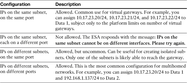
Figure 12-1 shows a common multihomed network configuration on an ESA.
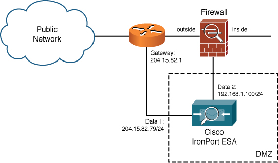
Figure 12-1. Multihomed ESA Configuration
Some of the reasons for considering a multihomed deployment include
• The network design dictates that ESA must span networks. This is called for if you have a public or DMZ interface, but the ESA also needs internal access to mail servers, DNS, or LDAP. It’s an alternative to making firewall exceptions that would allow the ESA to reach internal servers.
• You want to separate public and private traffic. If your ESAs act as MTA for internal-to-internal email message traffic in addition to being an Internet email gateway, you can isolate the local traffic to an inside interface.
• You need to isolate management interfaces from SMTP-related interfaces. If you have a separate network for common management tasks, like WUI and CLI administration, logging, and SNMP monitoring, you can add an ESA interface on that network, and restrict the management protocols to it.
You want to create a private network for email-related servers. For example, if you want to deploy encryption or DLP servers alongside your ESAs, allowing SMTP delivery to and from, you can segment all that traffic on a private subnet, as shown in Figure 12-2.
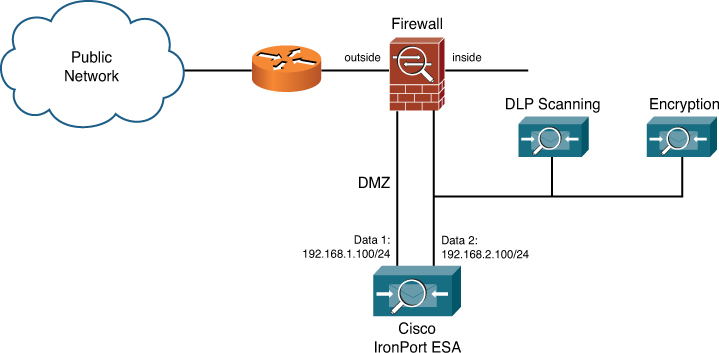
Figure 12-2. ESA with Private Subnet for Encryption or DLP Servers
Generally, if your network design calls for servers to have both DMZ and internal interfaces, the ESA can be configured to match. The goal for the ESA is flexibility to match any customer’s preferred deployment method.
Virtual Gateways
Virtual gateways refer to the ability of the ESA to have more than one IP address and hostname combination per appliance—virtual gateways bear no relationship to virtual machines or virtualization technology; the term is simply another way of indicating multiple interfaces on the same port, which can be used as additional delivery interfaces. In addition to multihoming, which is having IP addresses on multiple networks, the ESA can also have multiple IPs on the same network, giving the appearance of multiple separate machines. These interfaces work the same as any other and can be used for accepting messages (with a listener configured on them) or for delivering messages.
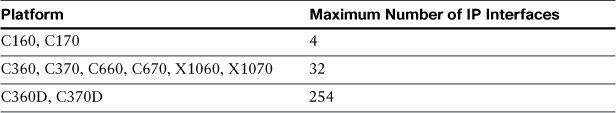
Support for virtual gateways is limited by platform. Table 12-2 lists the number of supported IP interfaces per appliance.
Table 12-2. Supported IP Interfaces per Appliance
Why would you use virtual gateways in production? The reasons generally boil down to segmentation of email traffic, whether incoming, outgoing, or both. Some examples of virtual gateway use include delivery, for sending out different kinds of traffic over different IP interfaces, or for receiving SMTP traffic on different IPs. We examine these uses later in this chapter, after I demonstrate how to add IP interfaces and named interface groups.
Adding New Interfaces and Groups
You can add new IP interfaces and hostnames to the ESA through the WUI page at Network à Interfaces or in the CLI using interfaceconfig. Every interface has a friendly name that’s used to identify it. This can be anything—a description of its usage, like “private” or “management,” the switch port number it’s connected to, almost anything. You can even make the name the same as the IP address and hostname. The friendly name of an interface is used in a few areas: In Listener setup, it’s used to associate the listener and port with an IP. You also see this name in the logs when connections go to and from the interface.
Groups of interfaces are just that—a friendly name for a set of IP interfaces. Groups of interfaces are only used for selecting delivery source for outbound SMTP connections. Instead of selecting a particular delivery interface to use as source IP for new connections, you select a group by name. The ESA then initiates new outbound SMTP connections from the IPs in the group using round-robin rotation.
You can only create groups in the CLI, and you can only use them in the CLI altsrchost table once created. Example 12-1 shows how to add interface groups using interfaceconfig.
Example 12-1. Creating Interface Groups
esa02.cisco.com> interfaceconfig
Currently configured interfaces:
1. DMZ (192.168.1.110/24 on Data 1: esa02.cisco.com)
2. DMZ2 (192.168.1.111/24 on Data 1: esa03.cisco.com)
3. DMZ3 (192.168.1.112/24 on Data 1: esa04.cisco.com)
Choose the operation you want to perform:
- NEW - Create a new interface.
- EDIT - Modify an interface.
- GROUPS - Define interface groups.
- DELETE - Remove an interface.
[]> groups
Currently configured IP groups:
No groups defined.
Choose the operation you want to perform:
- NEW - Create a new group.
[]> new
Enter the name for this group.
[]> Delivery
Enter the name or number of the interfaces to be included in this group.
Separate your choices with commas or specify a range with a dash.
1. DMZ (192.168.1.110/24: esa02.cisco.com)
2. DMZ2 (192.168.1.111/24: esa03.cisco.com)
3. DMZ3 (192.168.1.112/24: esa04.cisco.com)
[1]> 2-3
Group Delivery created.
Currently configured IP groups:
1. Delivery (DMZ3, DMZ2)
Choose the operation you want to perform:
- NEW - Create a new group.
- EDIT - Modify a group.
- DELETE - Remove a group.
[]>
As a result, the interface group I created here, Delivery, is now available to use for creating listeners or selecting delivery interfaces.
Using Virtual Gateways for Email Delivery
The primary use of virtual gateways is to segment the delivery of SMTP traffic, which means that you deliver different types of email messages using different VGs. Before I describe how to do this, I answer the “why” of traffic segmentation. Why bother using multiple IP addresses and hostnames to deliver email messages to the Internet?
The answer to this lies in the way that other organizations perceive you and your email traffic. Some sites may treat your email traffic as junk. Given the security and authentication problems with SMTP, and the overwhelming volumes of unwanted email traffic, it’s no wonder that many sites take a policy of “shoot first, ask questions later.” This means that traffic that might be fraudulent or illegal advertising will be rejected. Your traffic, as legitimate as it might be, can be lumped into the “junk” classification. The reaction that each organization will have varies, making it frustrating to troubleshoot each individual situation. Normally, the concern is that your delivery IPs will be listed with a public DNSBL or reputation service as being a spam source or that your SMTP connections will be rejected by major ISPs. Such an event can disrupt business.
Should everyone consider segmenting traffic across multiple IPs? Not necessarily. Your environment is a good candidate for segmenting if you have one or more of the following situations:
• Your organization sends out automated messaging of some type: statements, confirmations, or alerts, for example. You should segment this traffic from your person-to-person email.
• Your organization has some kind of opt-in advertising messaging. Bulk, automated messages, even when legitimately requested by subscribers, are often not well received. Service providers typically act on customer complaints by rejecting your connections.
• You have different classes of users within your organization. For example, in education, you have students, faculty, and staff. You might have contractors or temporary employees whose messaging should be handled separately.
• Your organization emails on behalf of other organizations, whether internal or external.
The point of segmenting traffic is to ensure that if advertising or other automated emails trigger anti-spam rules or public blacklisting, and the sending IP gets a poor reputation, your other mail delivery interfaces will not be affected by that poor score. If you separate your corporate user traffic from marketing messages using virtual gateways, delivery problems with marketing messages won’t affect delivery of your user email.
We discuss segmenting further in Chapter 14, “Recommended Configuration.”
Aside from these reasons, you might be interested in creating virtual gateways just in case of an emergency. I’m not suggesting you should actively seek to avoid other organization’s junk filtering without addressing the root cause, which won’t work anyway. I suggest that in cases where business-critical email is not being delivered because of a blacklisting, having another IP ready for failover can give you the breathing room to address the root cause.
Using virtual gateways is simple. Once an interface or interface group is added to an ESA and the change committed, you simply have to decide when to use them. The ESA must have a rule to determine which messages are delivered from which interface. Messages that do not match any rule are delivered from the default delivery interface. There are three places such a policy can be invoked: using the content filter action “Deliver from IP Interface,” the message filter action alt-src-host, or the CLI table available through the altsrchost command. The altsrchost table is simple, as there are only two criteria for selecting messages: the envelope sender address or the source IP injecting the message into the ESA. In other words, you can use the IP address that sent the message originally to decide which ESA interface will deliver it. Example 12-2 shows a session from the CLI, where I’m choosing the delivery interface for all the messages originating from a single source IP. I choose to use an interface group called Delivery, which includes two IP interfaces: DMZ2 and DMZ3.
Example 12-2. Using altsrchost to Select Delivery Interfaces
esa02.cisco.com> altsrchost
Choose the operation you want to perform:
- NEW - Create a new mapping.
- IMPORT - Load new mappings from a file.
[]> new
Enter the Envelope From address or client IP address for which you want to set up a
Virtual Gateway(tm) mapping. Partial addresses such as
"@example.com", "@.com", "user@", or "[email protected]" are allowed.
[]> 10.1.17.22
Which interface do you want to send messages for 10.1.17.22 from?
1. DMZ (192.168.1.110/24: esa02.cisco.com)
2. DMZ2 (192.168.1.111/24: esa03.cisco.com)
3. DMZ3 (192.168.1.112/24: esa04.cisco.com)
IP Groups:
4. Delivery (DMZ3, DMZ2)
[1]> 4
Mapping for 10.1.17.22 on interface Delivery created.
Choose the operation you want to perform:
- NEW - Create a new mapping.
- EDIT - Modify a mapping.
- DELETE - Remove a mapping.
- IMPORT - Load new mappings from a file.
- EXPORT - Export all mappings to a file.
- PRINT - Display all mappings.
- CLEAR - Remove all mappings.
[]>
If you need to segment traffic by other means, you must use a filter. Figure 12-3 shows an example of an outgoing content filter that delivers using the interface DMZ2 when messages are larger than 1 MB.
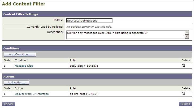
Figure 12-3. Outgoing Content Filter Showing Source Interface Selection
Other common selection criteria include recipient email address domain, LDAP group of the sender, or values in headers that indicate the source or use of messages.
Virtual Gateways and Listeners
The name “virtual gateways” implies that a whole new ESA pipeline is created, from listening to delivery. This is not the case. Virtual gateways are additional IPs intended for SMTP delivery, and listeners don’t have anything to do with delivery. By default, new interfaces do not automatically have listeners created and assigned to them. Email that is accepted only on a single listener can be separated and delivered across an arbitrary number of delivery interfaces.
This does not mean that you cannot create listeners on newly created interfaces. You can, and there are some good reasons to do so. However, adding additional interfaces, especially on public facing networks, adds complexity: As you make changes to connection controls using the HAT, you must do so for each listener. There’s little reason to segment incoming Internet email across multiple listeners. For outgoing email, or internal to internal, however, multiple listeners on a single ESA can segment traffic and policy effectively. We discuss the use cases for multiple listeners later in this chapter.
Note that multiple listeners provide for separate SMTP server capabilities at the start of the pipeline, including HAT, RAT, and LDAP checks. Once the messages are accepted, however, the ESA has only a single work queue and all messages pass through the same security and filtering pipeline.
Multiple Listeners
Virtual gateways can be used for more than just multiple outbound delivery hosts. Every IP interface on the ESA can have a listener assigned. You can also assign multiple listeners to each IP interface, provided that each listener is on a different port. Why would you need multiple listeners on an ESA?
The answer always comes down to the general architecture goal of segmentation. Whenever you have email messages originating from multiple sources, being treated with different policies on the ESA, separating listeners may offer some distinct advantages. If messages from different sources require different listener-wide settings, like masquerading or RAT, you must use multiple listeners. Listener-wide settings are applied to all messages accepted on any listener where they are configured.
Separating Incoming and Outgoing Mail
One case for multiple listeners is to separate incoming and outgoing email. If you have an ESA with a two-network installation, with one network interface “outside” and one “inside,” having two listeners may be a requirement.
Having a separate listener for outgoing mail allows you to construct a HAT that is simple and restrictive. An outgoing listener only needs one group and policy, with relay behavior. The default sender group should use the built-in BLOCKED policy. This HAT configuration is preconfigured for you when you create a new listener and choose the Private type.
Your outgoing mail listener is not restricted to a single HAT sender group. You might want to segment your internal sources into different HAT policies. For example, you could create a group and policy for Exchange servers that allow multiple simultaneous connections with no rate limiting, while grouping application servers into a policy that limits mail volume.
Multiple Outgoing Mail Listeners
Most organizations have email from different sources. Commonly, we think of email as “person to person,” where a real human being is sending messages to other human beings, whether remote or local. Another common type is machine-generated messages intended for human recipients, and this is a broad category that includes order confirmations, account statements, receipts, alerts, web server notifications, advertisements, flyers, invitations, and more. Rare is a website that doesn’t use email for some tasks, like enrollment confirmations, password change requests, or notifications.
These other email sources can be separated for delivery by the ESA using the virtual gateways techniques discussed earlier. You might also have a need to separate the acceptance of these messages into different listeners. There are a few good reasons to consider doing so:
• Do the different types of outgoing mail require different masquerading or domain map settings? These tables are applied to all messages on a given listener, so if you need separate settings for these, you must have different listeners.
• Are any of the outbound applications high volume, high concurrency, or aggressive in other ways? It makes sense to separate listeners to prevent any given application from crowding out other message sources. It’s not just public Internet senders that can exhibit bad SMTP behavior. Many internal applications don’t respond well to SMTP rate limits, rejected connections, or delays in acceptance, and a separate listener can isolate these problem servers.
• Does your network architecture mean that some application servers can’t reach your existing network interfaces?
• Do application servers use a nonstandard port? An individual ESA listener is tied to a single port. If you need to accept or relay mail on other ports, you must create a separate listener.
Separate Public MX from Submission
In some environments, mainly service providers and higher education, users are provided with an SMTP outgoing server IP or host where messages can be sent directly. The user’s mail clients send all messages to this IP, usually called a submission host, directly. In many cases, this submission host must be publicly available to support roaming users, and so is often provided right on the same mail servers that are the MX records for the domain, on the same port 25. SMTP AUTH is usually used, sometimes in conjunction with SSL/TLS. ESA supports this model, and can even require that hosts use TLS before being allowed to authenticate. You must provide some sort of authentication, either on ESA or another system, to prevent abuse of a submission service. ESA can be configured to not require authentication, so caution must be exercised.
Running submission on the same IP and port as your MX can be a security problem for a number of reasons. First, because the public MX and SMTP AUTH are combined, the HAT cannot control access and message limits separately. Second, such configurations mean that, in order to offer SMTP AUTH to anyone, you must offer it to everyone, because you won’t know the source IP of roaming users. Any client connecting to the ESA will see the AUTH extension in the ESMTP extensions list. Third, the general problem with SMTP AUTH, wherever it’s running, is that it only requires a username and password, and these can be brute-forced, cracked, stolen, or simply asked for. Spam senders spend a lot of time crafting messages to users seeking their credentials, and too many users happily comply with requests to “reset your account or we will be forced to suspend your email!”
By comparison, a separate submission listener can be run on the same ESA on a separate interface and port, and it has these advantages:
• Separate HAT: The separate HAT means completely different settings for the hosts that connect to the submission host. Your public MX listeners will have typical settings for general Internet email senders, while the submission listener will put severe limits on client volume.
• On the submission host, you have access control on a per-IP, CIDR range, or reputation basis. You can exclude entire countries or individual hosts that appear to be a source of exploit attempts.
• You can separately enforce the use of TLS, and specific ciphers, for all clients.
• You can aggressively rate limit all connecting hosts. For example, the submission policy can limit senders to a single simultaneous connection, one message per connection, and a limited number of recipients per hour. A limit of 100 or 250 recipients per hour, per connecting IP, shouldn’t bother legitimate users but will foil any attempts to use the service for high-volume spam.
• Control AUTH: SMTP authentication, which grants authorized users relay privilege, can be more selectively offered. Connecting clients will not see the AUTH extension on the public MX ESAs.
• Use a non-standard port: Although security by obscurity is not something you can rely on to deter attacks, offering a separate submission port can be part of the security strategy. Port 587 is the customary port for email submission, but any port can be used as long as the mail clients are configurable.
If you currently have a combined MX and submission host, and have run into problems with exploited accounts, you can move to a separated architecture. At the very least, separating submission from MX listeners allows you to isolate any problems with exploited clients.
ESA and Virtual LANs
Virtual local-area networks (VLAN) can be used to connect an ESA to more networks than the physical interfaces and routing limits normally allow. When you create a VLAN interface using the etherconfig command, you can also have a real IP address on the physical port so that it can handle both VLAN and non-VLAN traffic.
For a server role, like ESA, the chief value of VLAN support is segmentation and security. It’s also provided for compatibility with networks that use VLANs.
VLANs are easy to create and must be done in the CLI using the etherconfig command. Example 12-3 shows the process of creating the VLAN.
Example 12-3. Adding a VLAN Using etherconfig
esa02.cisco.com> etherconfig
Choose th operation you want to perform:
- MEDIA - View and edit ethernet media settings.
- VLAN - View and configure VLANs.
- LOOPBACK - View and configure Loopback.
- MTU - View and configure MTU.
[]> vlan
VLAN interfaces:
Choose the operation you want to perform:
- NEW - Create a new VLAN.
[]> new
VLAN tag ID for the interface (Ex: "34"):
[]> 2
Enter the name or number of the ethernet interface you wish bind to:
1. Data 1
2. Data 2
[1]> 1
VLAN interfaces:
1. VLAN 2 (Data 1)
Choose the operation you want to perform:
- NEW - Create a new VLAN.
- EDIT - Edit a VLAN.
- DELETE - Delete a VLAN.
[]>
Once the VLAN is created, you can assign IP interfaces to it as you would with any physical interface, as shown in Example 12-4.
Example 12-4. Assigning an IP Interface to a VLAN
esa02.cisco.com> interfaceconfig
Currently configured interfaces:
1. DMZ (192.168.1.110/24 on Data 1: esa02.cisco.com)
Choose the operation you want to perform:
- NEW - Create a new interface.
- EDIT - Modify an interface.
- GROUPS - Define interface groups.
- DELETE - Remove an interface.
[]> new
Please enter a name for this IP interface (Ex: "InternalNet"):
[]> ManagementVLAN
IP Address (Ex: 192.168.1.2):
[]> 192.168.3.110
Ethernet interface:
1. Data 1
2. Data 2
3. VLAN 2
[1]> 3
Netmask (Ex: "255.255.255.0" or "0xffffff00"):
[255.255.255.0]>
Hostname:
[]> mgmt02.cisco.com
Using VLANs on ESA is not especially common. It’s not a feature that I can point to for solving any particular problem. It falls into the category of “there if you need it,” and that you will likely know if your environment requires it.
Other Advanced Configurations
ESA offers a lot of features for network compatibility, but at the root, it is a UNIX-like network server. It is not a router, gateway, or firewall, and does not have any packet-routing capabilities or support for dynamic routing protocols. The network features that are available are intended for compatibility with your environment: The product feature focus is on Layer 7, not Layers 2–6.
Static Routing
Because the ESA is not a packet router, you have to explicitly state the routing path for networks that are not immediately Layer 3-adjacent to an interface on the ESA.
If you want to use the ESA to span multiple networks by assigning IP interfaces to the different physical (or VLAN) ports, you’ll find that you probably have to use static routing to define the path for packets to take to reach remote networks. The basic example is the default route: This is the destination that all packets will be sent to, if the destination of the packet is not network-adjacent to the ESA. All other routes you define must specify the destination network (using CIDR summaries) and the gateway where these packets should be sent.
Let’s look at another example, with a dual-homed ESA that occupies addresses in both the demilitarized zone (DMZ) and internally. Figure 12-4 shows this configuration.
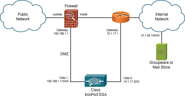
Figure 12-4. Dual-Homed Configuration
The default gateway for the system is the DMZ network’s router address, which is, in this case, the firewall. This is the proper configuration for a dual-homed ESA: The default gateway must lead “out” to the Internet, because static routes other than the default require destination addresses, and it’s not easily possible to summarize all Internet destinations.
If you simply install an ESA on two separate networks, and use a single default gateway, the ESA will not be able to communicate with some hosts in your network. Remember that the ESA has only two basic packet-routing rules (by default):
1. If the destination IP address is on the same subnet as one of the interfaces on the ESA, send the packet directly using that adjacent interface.
2. For all other destination IP addresses, send the packet to the default gateway using the interface adjacent to the default gateway.
In Figure 12-4, the ESA cannot reach or be reached by the network 10.1.29.0/24 because it does not have a route to it. Even if a server on that network sends a packet to the Data 2 interface on the ESA, the ESA sends the reply packet to the default gateway using the Data 1 IP address as the source. Even if this packet were actually routed back to the internal server, it would be discarded.
Luckily, this is easy to fix, by defining a gateway that can be used to reach the internal gateway. Any gateway listed in a static route must be directly adjacent to the ESA or reachable through another static route in the table. To reach this internal network, simply add a static route named Internal with a destination of 10.1.29.0/24 and a gateway of 10.1.17.1. Now, the routing rules for this ESA follow these steps:
1. If the destination IP address is on 192.168.1.0/24, send the packet directly to the destination using the Data 1 interface as source.
2. If the destination IP address is on 10.1.17.0/24, send the packet directly to the destination using the Data 2 interface as source.
3. If the destination IP address is on 10.1.29.0/24, send the packet to the gateway 10.1.17.1 using the Data 2 interface as source.
4. Send all other packets to the gateway 192.168.1.1 using the Data 1 interface as source.
Figure 12-5 shows the static routes for such a configuration in the Routing table in the Network menu of the WUI.
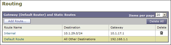
Figure 12-5. Static Routes for a Dual-Homed ESA That Must Reach an Internal Network
You can also define static routes in the CLI using the command routeconfig, but you can only modify the default gateway using the command setgateway.
If there is more than one internal network range, you either have to define the networks and their gateways individually, or by summarizing the internal networks. Many organizations use the RFC 1918 address space for internal networks, and provide a single internal gateway. If that’s the case in your network, you can use a static route for destinations, such as 10.0.0.0/8.
Transport Layer Security
SMTP is originally by definition a clear-text transport. From originating mail user agent (MUA) to destination MUA, with all Message Transfer Agent (MTA) hops in between, all SMTP commands and all message data is transmitted in the clear. More recently, RFC 3207 defines support in ESMTP for encrypting the SMTP conversation and all data between client and server using the ESMTP STARTTLS extension command. Transport Layer Security (TLS) is the protocol used for encryption. TLS is more commonly known as Secure Sockets Layer (SSL) and, in fact, TLS 1.0 and SSL 3.1 are identical except for the name. Going forward, new versions of the protocol will use the acronym TLS.
For SMTP, TLS is a point-to-point protocol that establishes an encryption session between two servers, regardless of the number of Layer 3 hops in between. The STARTTLS command begins the process of negotiation, where the client and server must agree on cipher, key length, and padding.
To use TLS, the client and server must both support ESMTP and the client must begin the conversation with EHLO. Then, the server must list STARTTLS in the ESMTP extension list:
220 mail.chrisporter.com ESMTP
ehlo cisco.com
250-mail.chrisporter.com
250-8BITMIME
250-SIZE 20971520
250 STARTTLS
If advertised, the client machine can request the negotiation by issuing the STARTTLS command. A client may issue STARTTLS even if it’s not advertised, and the response from the server will indicate acceptance or not. Typically, STARTTLS is issued as the first command, before MAIL FROM, but this is not strictly required. The ESA accepts TLS negotiation at any point in the conversation.
TLS uses certificates for storing and transmitting information about the server, including identification information and the server’s public key. The public key in the certificate is used to encrypt a session key, and that session key is used in a negotiated symmetric cipher for actually encrypting data. The certificate also contains identification information, which you can use for identity verification. We discuss TLS verification next.
If you’ve used secure websites, indicated by a URL starting with https://, you’ve used TLS. The web browser requests a certificate from the server, validates the data in the certificate, and uses the certificate public key to encrypt a session key. If the data in the certificate doesn’t match the website, or is not issued by a trusted authority, the browser can prompt the user. The process for two SMTP servers is similar, although there’s no ability to prompt the user because TLS is strictly machine-to-machine.
Using and Enforcing TLS When Delivering Email
When the ESA is the SMTP client, the Destination Controls table is used to decide if TLS should be attempted. Destination controls provides a default setting, and individual entries in the table can define the TLS policy for an individual destination domain.
Figure 12-6 shows the destination controls table with several entries. This table is used for defining destination-specific policies other than TLS, but we restrict this discussion at this point to encrypting communications.
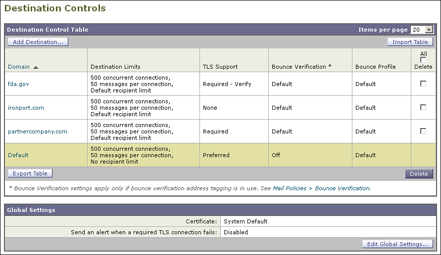
Figure 12-6. TLS Settings in the Destination Controls Table
There are five possible settings for TLS in each Destination Controls entry:
• None: TLS is not attempted even if the server advertises it. All SMTP data is transferred in the clear.
• Preferred: TLS will be attempted if the server advertises it. If TLS negotiation fails, or if the server does not advertise or rejects the STARTTLS command, ESA falls back to plain-text delivery of the message.
• Required: TLS will be attempted if the server advertises it. If TLS negotiation fails, or if the server does not advertise or rejects the STARTTLS command, the ESA does not fall back to plain-text delivery. Instead, messages to destinations marked Required will queue, retried periodically until either TLS is available or the message exceeds its maximum time in queue. You can optionally configure the ESA to alert an administrator or even the original sender if TLS cannot be negotiated to a Required domain.
• Preferred — Verify: Just as with Preferred, TLS will be attempted if the server advertises it, but the additional step of verifying the server’s certificate will be taken. TLS will only proceed if the certificate meets the validity tests, which are described later. If the certificate fails the check, TLS is not used, and the ESA falls back to plain-text delivery of the message.
• Required — Verify: TLS must be used, and further, the remote server’s certificate must pass the validity checks. ESA does not fall back to plain-text delivery under any circumstance.
Because TLS required does not allow for the delivery of mail in the absence of TLS support, and because many organizations and providers do not support TLS, you should almost never set the Destination Controls default to TLS Required. The only exceptions would be for ESAs that are being used purely internally with no delivery to Internet destinations.
To test TLS connectivity before setting a policy like Required or Verify, use the CLI command tlsverify. This command tests a TLS connection to a remote SMTP server and returns the results of a certificate validation test. You need two pieces of information: an envelope recipient domain and a remote server to test. Example 12-5 shows an example of the verification output.
Example 12-5. Using tlsverify to Test Secure Connections
esa02.cisco.com> tlsverify
Enter the TLS domain to verify against:
[]> cisco.com
Enter the destination host to connect to. Append the port (example.com:26) if you
are not connecting on port 25:
[cisco.com]> sj-inbound-e.cisco.com
Connecting to 128.107.243.14 on port 25.
Connected to 128.107.243.14 from interface 10.60.10.10.
Checking TLS connection.
TLS connection established: protocol TLSv1, cipher RC4-SHA.
Verifying peer certificate.
Verifying certificate common name sj-inbound-e.cisco.com.
TLS certificate match sj-inbound-e.cisco.com
TLS certificate verified.
TLS connection to 128.107.243.14 succeeded.
TLS successfully connected to sj-inbound-e.cisco.com.
TLS verification completed.
Would you like to verify another domain? [Y]>
Further, because many SMTP servers that support TLS do not have a certificate that will pass verification, I recommend against using Preferred — Verify as a default. Enforcing certificate validity results in ESA not using TLS with most destinations.
Take care with the TLS Required setting and either of the Verify options. TLS Required causes email delivery delays, at a minimum, if a server does not support TLS. You should verify TLS capabilities with the CLI command tlsverify before using this setting.
Many SMTP servers on the Internet support TLS, but do not have a certificate that will pass verification. If you choose the verify option, the ESA will not be able to use TLS. Again, verify TLS capabilities and certificate verification status using the tlsverify command before using this setting.
Using and Enforcing TLS When Receiving Email
When the ESA is the SMTP server, TLS settings are controlled in the HAT mail flow policy that is applied to the sendergroup that the connecting IP falls into. Because the mail flow policy controls almost all aspects of the ESA’s responses to SMTP commands, it makes sense for TLS to be specified here.
From initial setup, most of the HAT mail flow policies inherit their TLS setting from the default mail flow policy. If you just want to support TLS for all senders, and not just specific senders, I recommend changing the default mail flow policy to Preferred.
There are three settings for TLS in each mail flow policy:
• None: TLS is not advertised by the ESA in the list of ESMTP extensions, and the ESA responds with 500 #5.5.1 command not recognized to the STARTTLS command.
• Preferred: TLS is advertised by the ESA in the list of ESMTP extensions, but it is left to the client to decide whether to issue the STARTTLS command. Email will be accepted even if TLS is not negotiated.
• Required: TLS is advertised by the ESA, and enforces the use by disallowing any command other than STARTTLS. Any other command (except quit) will receive the response 530 #5.7.0 Must issue a STARTTLS command first.
As you can see, TLS Required is somewhat dangerous: It will prevent a client from delivering email unless TLS is available. If the client is rejected because TLS is not available, the client may decide to queue and retry the message, or may treat it as a permanent failure and bounce the message. Just as with delivery, I recommend against setting a default TLS policy of Required, unless the ESA is being used as an internal server and not receiving email from Internet clients.
In most organizations, the policies for TLS on an Internet-facing ESA should be Preferred in the default policy settings, with Required only for a policy like TRUSTED, or better yet in a specific TLSREQUIRED sendergroup and policy. Care should be taken when adding senders to a TLSREQUIRED sendergroup, and you should be certain that the sender is already successfully using TLS in a Preferred policy before adding her to a Required policy.
Notice that the Verify options are not available in Mail Flow Policy TLS settings. This is because the TLS protocol operates chiefly with the server’s certificate, and not the client. When acting as the server, it’s the certificates installed on the ESA that are potentially being verified by the connecting client. Although TLS does support client certificates, they are rarely used in ESMTP STARTTLS over the public Internet. It is not possible to force ESA to verify a client certificate and it does not require a client certificate during negotiation.
Certificate Validation
When delivering messages to an SMTP server using TLS, the ESA can also optionally verify the server certificate that the ESA, as client, is being presented with by the remote server. TLS certificate verification varies among vendors, but the ESA goes through these steps, all of which must pass for the certificate to be considered verified:
• The certificate must not be expired. X509 certificates have a Validity field with start and end dates; the current date and time must fall into this range. This means that date and time for your ESA must be set accurately.
• The certificate must be signed by either (1) a certificate from a known certificate authority (CA) that the ESA has in its configuration, or (2) signed by an intermediate certificate that in turn is signed by a known root certificate. The process of verifying the signature from the certificate, to the intermediate (and potentially then to other intermediates), to the root certificate is called chaining. In other words, the remote certificate must either be signed by a root or be chained back to a root via intermediates.
• The identity of the remote server must match the identity stored in the certificate. There can be several different meanings of identity. At least one of these must match for the identity to be verified:
• The hostname listed in the certificate’s common name (CN) field must match the DNS hostname to which the ESA is connecting.
• The hostname listed in the certificate’s CN field must match the domain portion of the envelope recipient address on the message. For example, it’s considered a match if delivering to [email protected] and the certificate CN is cisco.com.
The ESA ships with a fairly standard list of root certificates from well-known certificate authorities. Most CAs have more than one root certificate, so the list is fairly long and should cover almost every certificate you’re likely to encounter on an Internet-facing MTA. The ESA allows you to manage the list of trusted root certificates, so that you can add a trusted root CA certificate, or even to remove some from the standard list. Many government organizations maintain their own root certificate authority that is not signed by any other well-known root. If you want these to pass the verification test, you need to add the root CA to your ESAs. This is easily done in the WUI Network → Certificates page.
Certificate verification also occurs when the ESA is the SMTP server, but in this case, it’s the remote client that is doing the verification. Even if remote clients aren’t usually performing certificate verification, some always will. If the goal is to use TLS wherever possible, I recommend using a certificate on your ESAs that will pass the verification tests.
Managing Certificates
If you expect to do a lot of TLS communication, and most organizations do, plan to purchase and install a TLS certificate from a well-known Internet root CA. The certificate identifies your ESA and provides a public key for the client to use when exchanging encryption keys for the data to be sent. After the client issues the STARTTLS ESMTP command, the certificate is the first information the client requests.
The process of obtaining a certificate varies with the CA you choose. Most root CAs have a website that allows you to manage and request your certificates. Some CAs require a Certificate Signing Request (CSR) that you can generate directly on the ESA with a new feature that’s part of AsyncOS 7.1.
The certificate you buy should pass all the verification steps listed in the previous section. Having a valid, unexpired cert from a well-known root authority is the easy part. It can be a little more confusing to decide what, exactly, should go into the certificate’s CN field. In general, you should have the external hostname of your ESAs in the CN field. This is the hostname that external SMTP clients see in your MX records. For example, if your MX records are
yourdomain.org. IN MX 10 smtp1.yourdomain.org.
yourdomain.org. IN MX 20 smtp2.yourdomain.org.
You should buy certificates with CNs of smtp1.yourdomain.org and smtp2.yourdomain.org and apply them to the respective ESAs. Simple, right?
It’s not always so straightforward. There are a few other possible scenarios, depending on your deployment. For load-balanced ESAs behind a single MX, you might have this in DNS:
yourdomain.org. IN MX 10 smtp.yourdomain.org.
But, that hostname resolves to a VIP on a load balancer, and you have more than one ESA behind that VIP. Again, the CN in the cert should have the external hostname, which in this case, is smtp.yourdomain.org. All the ESAs behind this VIP should have the same hostname, or even the same certificate, regardless of their actual internal hostnames.
Because certificates have such reliance on hostnames, it’s worth going over some of the requirements. In addition to the verification steps just described, some SMTP clients go even further in their verification, requiring that the SMTP greeting supplied by the server include a hostname that matches the certificate CN. In other words, SMTP clients want to see this when they connect:
220 smtp.yourdomain.org ESMTP
The ESA displays in this banner the hostname assigned to the IP interface that is accepting the connection. This hostname should match the external hostname that Internet clients will see. For load-balanced ESAs, this means that the external-facing IP interface should all have the exact same hostname. To keep all the ESAs separate internally, set a different global hostname for each ESA using sethostname. You can also override the hostname banner with a custom value using the HAT.
If your ESAs have internal (RFC 1918) addresses and are being NATted to Internet-routable addresses, you may have different internal hostnames for your ESAs. Remember that verification is being done on the hostnames that the external Internet SMTP clients see, and your IP interfaces should match that external hostname.
Another certificate option is wildcard certificates that some CAs offer. These are issued and function like any other certificate, but they are valid for more than one hostname. They are generally valid for an unlimited number of hosts or subdomains of your parent domain. For example, the wildcard certificate *.yourdomain.org can be used for hosts named smtp1.yourdomain.org, smtp2.yourdomain.org, and smtp3.yourdomain.org. Wildcard certificates tend to be more expensive than single-host certificates and can only wildcard a single level of subdomain. For example, the wildcard certificate *.mx.yourdomain.org will not match smtp1.yourdomain.org.
Adding Certificates to the ESA
When you receive certificates that you purchased from a CA, or you generate a self-signed certificate, there are two ways to add it to the ESA configuration. The easiest is through the WUI, in the Certificates page in the Network tab. This is straightforward and requires that you have the certificates available in a local file, in Public Key Cryptography Standard 12 (PKCS12) format, which is the most common format used for distributing certificates. The PKCS12 file has both an X.509 certificate, including the public key, and the corresponding private key, all protected with a password. That single file contains everything you need for importing a certificate on the ESA.
Adding certificates via the CLI is less straightforward and requires a different format. The CLI command certconfig is used to create new certificates and manage existing ones. The CLI commands expect the private key, certificate, and any intermediate certificates, each pasted separately in Privacy Enhanced Mail (PEM) format. PEM format represents its data encoded with Base64 to US-ASCII format, much like MIME Base64 encoding.
PEM format certificates are easily recognized because the encoded data is bracketed with these header and footer lines:
-----BEGIN CERTIFICATE-----
-----END CERTIFICATE-----
PEM format private keys are similar, but bracket the data with these header and footer lines:
-----BEGIN RSA PRIVATE KEY-----
-----END RSA PRIVATE KEY-----
If you have the certificate and private key in PEM format files, open them in a text editor so that you can copy and paste the data, including the header and footer. Example 12-6 shows the import process that pastes the certificates into the CLI session. I excised some of the actual certificate data for brevity.
Example 12-6. Using certconfig to Import a New TLS Certificate and Private Key
esa02.cisco.com> certconfig
Choose the operation you want to perform:
- CERTIFICATE - Import, Create a request, Edit or Remove Certificate Profiles
- CERTAUTHORITY - Manage System and Customized Authorities
[]> certificate
List of Certificates
Name Common Name Issued By Status Remaining
--------- -------------------- -------------------- ------------- ---------
Demo Cisco Appliance Demo Cisco Appliance Demo Active 2797 days
Choose the operation you want to perform:
- IMPORT - Import a certificate from a local PKCS#12 file
- PASTE - Paste a certificate into the CLI
- NEW - Create a self-signed certificate and CSR
- EDIT - Update certificate or view the signing request
- EXPORT - Export a certificate
- DELETE - Remove a certificate
- PRINT - View certificates assigned to services
[]> paste
Enter a name for this certificate profile:
> example
Paste public certificate in PEM format (end with '.'):
-----BEGIN CERTIFICATE-----
MIIDpjCCAo4CCQDdRnDQojP+4DANBgkqhkiG9w0BAQUFADCBlDELMAkGA1UEBhMC
...
sDkZLS756XTpMTPSjB6TZBpLV/NcDERKuXc=
-----END CERTIFICATE-----
.
C=US,ST=New York,L=New York,O=example.com,CN=mail.example.com,emailAddress=chris@
example.com
Paste private key in PEM format (end with '.'):
-----BEGIN RSA PRIVATE KEY-----
MIIEpAIBAAKCAQEAqkzgVHRXDknOAePMZICDIQnlQQtd/GHHdTi3lGZQboF/jwOL
...
dqQgnxXod7+X9frXk9RE94pvKen2cfl3QWN5V6Sks03Bis7n02x/Ag==
-----END RSA PRIVATE KEY-----
.
Do you want to add an intermediate certificate? [N]>
List of Certificates
Name Common Name Issued By Status Remaining
--------- -------------------- -------------------- ------------- ---------
example mail.chrisporter.com mail.chrisporter.com Valid 3270 days
Demo Cisco Appliance Demo Cisco Appliance Demo Active 2797 days
If you have certificates in a format other than PKCS12 or PEM, you cannot natively import them into the ESA. The good news is that certificate files are fairly easy to convert from one format to another using the openssl utility for UNIX or Windows, which is available from www.openssl.org if you don’t have it already. Most UNIX and similar systems, like MacOS, include the openssl library and utilities. The openssl utility is not available on the ESA, so the following examples must be run on another system.
For example, if you have certificates and keys in the Distinguished Encoding Rules (DER) binary format, you can convert them to PEM with this command:
openssl x509 -outform pem -inform der -in cert.der -out cert.perm
You can also convert PEM and DER formats to a single PKCS12 package, assuming you have both the certificate and the private key in separate files:
openssl pkcs12 -export -out cert.p12 -inkey private.key –in cert.pem
The openssl utility has many other certificate features like creating self-signed certificates, viewing certificate details, and converting other formats. These capabilities are beyond the scope of this book, but are useful to know for anyone working with TLS.
TLS Cipher and Security Options
The TLS negotiation process involves selecting a symmetric cipher and key length that will be used to actually encrypt the data being transmitted. Typically, the server lists the available supported ciphers, and the client picks the first in the list that it supports. If the client and server do not share a supported cipher in common, the TLS negotiation fails, and message delivery may be delayed, or may drop to plain-text SMTP delivery.
Because shorter cipher key lengths are higher performance, the ESA defaults to listing ciphers in strength order, starting with the shorter (weakest) ciphers first. This provides good security at fair performance, but you may be interested in higher security
Modifying the TLS and SSL parameters, including ciphers, is only done in the CLI using the sslconfig command. The initial menu for sslconfig, shown in Example 12-7, shows you the current settings and provides options to modify those settings for each area where TLS is used.
Example 12-7. Cipher Settings Listed in sslconfig
esa02.cisco.com> sslconfig
sslconfig settings:
GUI HTTPS method: sslv3tlsv1
GUI HTTPS ciphers: RC4-SHA:RC4-MD5:ALL
Inbound SMTP method: sslv3tlsv1
Inbound SMTP ciphers: RC4-SHA:RC4-MD5:ALL
Outbound SMTP method: sslv3tlsv1
Outbound SMTP ciphers: RC4-SHA:RC4-MD5:ALL
Choose the operation you want to perform:
- GUI - Edit GUI HTTPS ssl settings.
- INBOUND - Edit Inbound SMTP ssl settings.
- OUTBOUND - Edit Outbound SMTP ssl settings.
- VERIFY - Verify and show ssl cipher list.
[]>
The VERIFY submenu shows you all the available SSL ciphers currently available on the ESA. All the other configuration menu items are the same. Example 12-8 shows a modification to the INBOUND settings and ciphers.
Example 12-8. Modifying Ciphers with sslconfig
esa02.cisco.com> sslconfig
sslconfig settings:
GUI HTTPS method: sslv3tlsv1
GUI HTTPS ciphers: RC4-SHA:RC4-MD5:ALL
Inbound SMTP method: sslv3tlsv1
Inbound SMTP ciphers: RC4-SHA:RC4-MD5:ALL
Outbound SMTP method: sslv3tlsv1
Outbound SMTP ciphers: RC4-SHA:RC4-MD5:ALL
Choose the operation you want to perform:
- GUI - Edit GUI HTTPS ssl settings.
- INBOUND - Edit Inbound SMTP ssl settings.
- OUTBOUND - Edit Outbound SMTP ssl settings.
- VERIFY - Verify and show ssl cipher list.
[]> inbound
Enter the inbound SMTP ssl method you want to use.
1. SSL v2.
2. SSL v3
3. TLS v1
4. SSL v2 and v3
5. SSL v3 and TLS v1
6. SSL v2, v3 and TLS v1
[5]> 3
Enter the inbound SMTP ssl cipher you want to use.
[RC4-SHA:RC4-MD5:ALL]> MEDIUM:HIGH:-aNULL:@STRENGTH
i
sslconfig settings:
GUI HTTPS method: sslv3tlsv1
GUI HTTPS ciphers: RC4-SHA:RC4-MD5:ALL
Inbound SMTP method: tlsv1
Inbound SMTP ciphers: MEDIUM:HIGH:-aNULL:@STRENGTH
Outbound SMTP method: sslv3tlsv1
Outbound SMTP ciphers: RC4-SHA:RC4-MD5:ALL
Choose the operation you want to perform:
- GUI - Edit GUI HTTPS ssl settings.
- INBOUND - Edit Inbound SMTP ssl settings.
- OUTBOUND - Edit Outbound SMTP ssl settings.
- VERIFY - Verify and show ssl cipher list.
[]>
The first question that it asks is which protocol versions to allow. Despite the name change, SSL and TLS are similar; you can think of TLS v1.0 as SSL v3.1. Because of known weaknesses, the software no longer supports SSLv1, and it’s strongly recommended that you do not use SSLv2. It’s still available in the ESA as of this writing, but it’s strictly for compatibility reasons. The default is to support SSLv3 and TLSv1 only.
The next question asks you which SMTP SSL ciphers you want to support, and which order to present or select them in. The answer to the SMTP SSL cipher question is a bit odd—it doesn’t give you a friendly menu to choose from, but requires that you use an OpenSSL style cipher list. The format is a comma-separated list of cipher names or special keywords. Table 12-3 describes the meaning of these names.
Table 12-3. SSLconfig Cipher List Entries
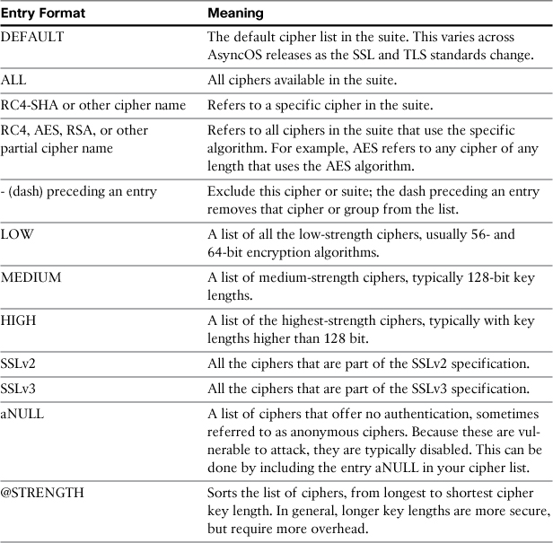
In the previous example, I configured the TLS settings to include both the medium- and high-strength ciphers. I disabled the use of NULL ciphers. Finally, the @STRENGTH keyword sorts the list by key length, starting with the strongest ciphers. In essence, this setting can be described as “Exclude the low-strength and anonymous ciphers, and prefer the ciphers with the longest key lengths.”
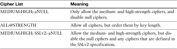
Table 12-4 shows some other common options.
Table 12-4. Common Cipher Lists for sslconfig
Split DNS
Like any SMTP MTA, the ESAs heavily depend on functioning DNS to perform lookups prior to delivering messages. DNS is also the transport for SenderBase Reputation Scores (SBRS), DNSBL entries, forward (A) and reverse (PTR) lookups, and any domain or host-level matching in HAT sender groups. As a result, an ESA can make as many as seven DNS queries for every inbound connection. More DNS queries are made for delivery, log transfers, and administrative logins. In short, the ESA makes a lot of DNS requests, and its performance and many of its security capabilities depend on DNS servers that can properly handle the volume.
The most common DNS configuration is for ESA to use one or more local caching DNS servers that can answer A, MX, PTR, and TXT queries. These DNS servers can be part of your organization’s environment, or provided by your Internet service provider (ISP), but they should be on a “nearby” network via a low-latency path. In large environments, there would ideally be dedicated DNS servers that can handle thousands of queries per second.
If you don’t have such dedicated DNS servers, or you’d prefer not to handle it internally, there’s another option. The ESAs have a DNS setting for “Internet Root Servers,” configurable through the CLI with the dnsconfig command or in the WUI under Network → DNS. Here’s what the configuration looks like in the CLI:
esa02.cisco.com> dnsconfig
Currently using the Internet root DNS servers.
No alternate authoritative servers configured.
Choose the operation you want to perform:
- NEW - Add a new server.
- SETUP - Configure general settings.
[]>
The WUI DNS page is shown in Figure 12-7.
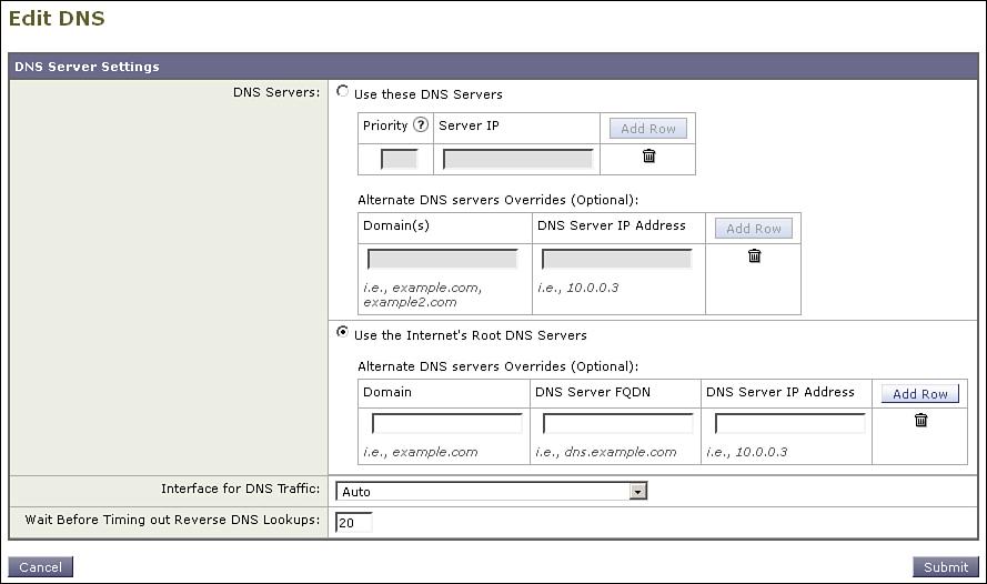
Figure 12-7. ESA DNS Settings Using the Internet’s Root DNS Servers
In this mode, the ESA acts as its own DNS server. It uses the list of well-known root servers (named a.root-servers.net through m.root-servers.net) to look up name servers for top-level domains, like .com and .net, and then recursively to name servers for each individual domain and subdomain. The ESA can resolve any host or domain that has public name servers available. It caches the results according to the TTLs on the DNS query responses.
The advantage of this configuration is that you no longer have the load of DNS queries falling on your local servers; instead, the queries are performed internally on the ESA, and the DNS resolver contacts the appropriate name servers across the Internet directly, using port 53 UDP and TCP connections.
Some of the disadvantages of this approach are
• Each ESA must act as its own resolver and do not share query results. The ESA cannot act as a DNS server for any other clients. This means that each ESA will make thousands of queries to Internet destinations for name resolution, depending on your connection volume.
• You must open port 53 from the ESAs to all Internet destinations on both UDP and TCP. Name servers to be queried can be found on any Internet address range, and the DNS protocol requires both UDP and TCP connections.
• The Internet DNS name servers have no knowledge of your internal DNS servers, and hence no knowledge of internal hostnames or IP ranges. In particular, RFC 1918 ranges, like 192.168.0.0/16 and 10.0.0.0/8, are not resolvable through public Internet name servers.
We can resolve the last of these by using a split DNS configuration on the ESA. Split DNS tells the ESAs to use the Internet root servers for general DNS lookups, but to use an alternate DNS server for your local domain or domains. Such a configuration is shown in Figure 12-8.
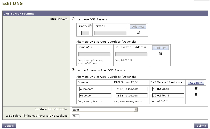
Figure 12-8. Split DNS Configuration
In that environment, lookups for hosts like mail.ironport.com, smtp1.fda.gov, and gmail-smtp-in.l.google.com will all be recursively resolved by the ESA itself using the Internet’s root DNS servers, but lookups for exchange.cisco.com and encryption.cisco.com would go to one of the two name servers listed for that domain.
What about private address space and PTR lookups? If you try to use the Internet’s DNS hierarchy to lookup hostnames for addresses in 10.0.0.0/8 or 192.168.0.0/16, you’ll get a “nonexistent hostname” response. To get the ESA to use your local DNS server for these private IP ranges, you need to be creative about your settings in DNS.
Recall that a PTR lookup performed like this:
nslookup 10.11.22.33
Is actually doing a DNS lookup on a host named 33.22.11.10.in-addr.arpa. The octets of the IP address are reversed, and the domain in-addr.arpa is added. We can exploit this by specifying an alternate DNS server for the domain 10.in-addr.arp for the 10.0.0.0/8 address space, and 168.192.in-addr.arpa for the 192.168.0.0/16 address space. Such a configuration is shown in Figure 12-9.
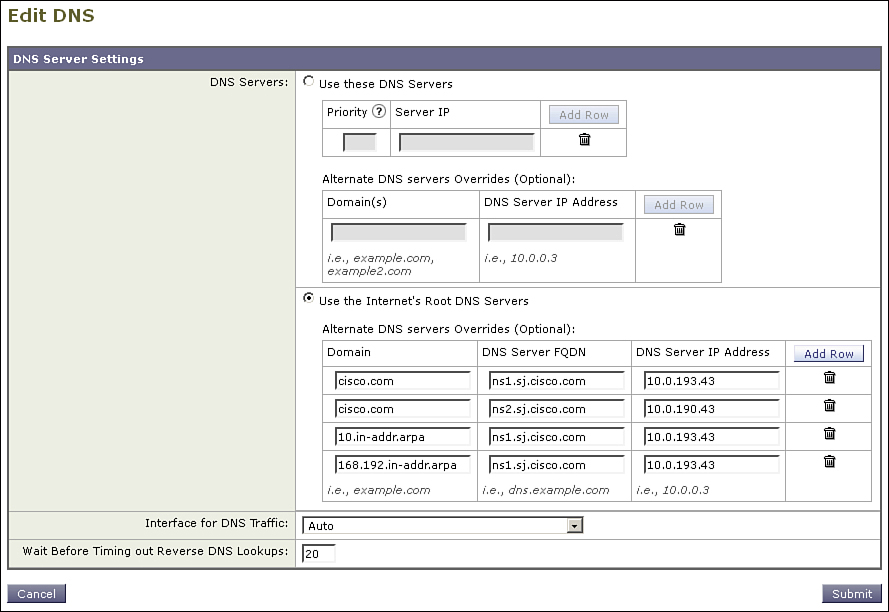
Figure 12-9. Split DNS Configuration with Reverse Zones
Load Balancers and Direct Server Return (DSR)
As we see in Chapter 13, “Multiple Device Deployments,” dedicated hardware or software load balancers can offer deployment flexibility for multiple ESAs in an email environment.
Normally, using a load balancer requires no change to your ESA configuration, other than planning your architecture and assigning IP addresses appropriately. For load-balancer configurations that use Direct Server Return (DSR), however, the ESA requires a change to create a loopback interface.
Most load balancers support some type of DSR, where the server behind the load balancer responds directly to the client, instead of back to the load balancer. The initial TCP handshake is between the load balancer and the client, but after that traffic from the server to the client is done directly, instead of going back through the load balancer. The response traffic doesn’t have to traverse the load balancer, reducing the resource pressure on the load balancer. For protocols that have heavy traffic on the server to client path, like HTTP web servers, this can be a significant advantage. With SMTP, which is conversational in model, and not request-response, it is of less advantage. If you are embarking on a new load-balanced email environment, DSR is not worth the effort for SMTP.
If you already have a DSR environment, you need to configure the ESAs with a loopback address for the direct return to work. This is only available in the CLI with the command etherconfig, as shown in Example 12-9.
Example 12-9. Creating a Loopback Interface with etherconfig
esa02.cisco.com> etherconfig
Choose the operation you want to perform:
- MEDIA - View and edit ethernet media settings.
- VLAN - View and configure VLANs.
- LOOPBACK - View and configure Loopback.
- MTU - View and configure MTU.
[]> loopback
Currently configured loopback interface:
Choose the operation you want to perform:
- ENABLE - Enable Loopback Interface.
[]> enable
Currently configured loopback interface:
1. Loopback
Choose the operation you want to perform:
- DISABLE - Disable Loopback Interface.
[]>
Once created, you can add IP interfaces to the loopback interface just as you can with the physical Ethernet ports, as shown in Example 12-10.
Example 12-10. Assigning an IP Address to a Loopback Interface
esa02.cisco.com> interfaceconfig
Currently configured interfaces:
1. DMZ (192.168.1.110/24 on Data 1: esa02.cisco.com)
2. Internal (10.1.17.22/24 on Data 2: mgmt02.cisco.com)
Choose the operation you want to perform:
- NEW - Create a new interface.
- EDIT - Modify an interface.
- GROUPS - Define interface groups.
- DELETE - Remove an interface.
[]> new
Please enter a name for this IP interface (Ex: "InternalNet"):
[]> Lo0
IP Address (Ex: 192.168.1.2):
[]> 192.168.7.110
Ethernet interface:
1. Data 1
2. Data 2
3. Loopback
[1]> 3
DSR works by using MAC address translation. When a new SMTP connection is made to the load balancer’s public virtual IP (VIP), the load balancer modifies the destination MAC address of packets from the client to match the MAC of the ESA. It does not modify the original source IP, which is the client’s, or the destination IP address, which is the load balancer VIP. Table 12-5 lists the steps in a sample DSR process.
Table 12-5. Steps in Load Balancer Direct Server Return
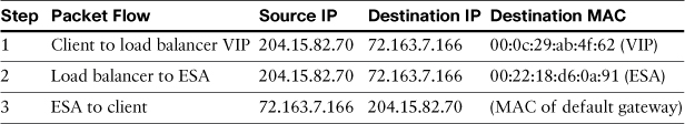
When the packet arrives at the ESA because the MAC has been rewritten, the ESA ignores it unless the destination IP matches a local interface. In other words, the ESA is not a promiscuous listener. To get around this, you must assign the load balancer’s VIP to the ESA, but having two servers with the same IP would result in Address Resolution Protocol (ARP) errors as two machines with different MACs respond to the same IP. The loopback interface doesn’t actually operate on any of the physical Ethernet ports, and doesn’t respond to ARP requests, allowing the ESA to accept the packets without conflicting with the load balancer.
Summary
This chapter looked at some of the more complex ways to configure the ESA networking for compatibility with a wide variety of environments. Because the MTA and security capabilities are almost identical regardless of network topology, you should choose a deployment mode that suits your network. In whatever deployment model you use, virtual gateways are extremely useful for segmenting delivery.
We also covered other network features like TLS and their associated certificates, and some less commonly used but important features like VLANs and loopback interfaces.
Up to this point in the book, we focused on configuring an individual ESA, but nearly every single ESA deployment will involve more than one appliance, and so we tackle deploying and managing multiple devices in the next chapter.