
Chapter 13. Multiple Device Deployments
In this chapter, you will learn the following:
• Reasons for deploying multiple systems, including performance, capacity growth, redundancy, and disaster recovery
• Decide how to deploy multiple systems to get the most use out of them
• Discussion of common deployment architectures
General Deployment Guidelines
This chapter covers a wide range of deployment scenarios when you want to run more than one Email Security Appliance (ESA). Because this covers virtually all ESA deployments, multiple system deployments are the norm rather than the exception.
Architecture and deployment topics cover the entire email environment from perimeter to end user. This book focuses on the ESA, of course, but issues concerning other components will be addressed. I cover the use of ESAs in various roles and the use of third-party products for tasks like email encryption and archiving. Throughout, I also use the term groupware or mailstore to refer to servers that accept email messages, store them, and provide a means of retrieval by mail user agents (MUA). Products that fall into the definition of groupware include Microsoft Exchange, Lotus Notes, and many commercial and open source products on UNIX systems that use local mail clients, IMAP, POP, or HTTP webmail interfaces.
I recommend a few general guidelines on deployments to all organizations that use the ESA:
• The ESA should be the first SMTP “hop” in to your network for incoming mail, and the last hop for outgoing mail. Being the first incoming hop allows all the ESA connection-based security filters to effectively do their job. Being the last outgoing hop frees all of your internal email enabled hosts of the hassle of dealing with Internet email delivery. Making the ESAs your only mail gateway provides a number of advantages:
• Single point of enforcement for all email policies. Whether enforcing rules on attachments, disclaimers, confidential information disclosure, regulatory compliance, or encryption, one set of rules across a cluster of ESAs makes rule enforcement easier.
• Consistent application of authentication standards. The emergence of Sender Policy Framework (SPF) and Domain Keys Identified Mail (DKIM) as standards for host- and message-based sender authentication means that it is more important than ever to control the use of email addresses within your domains, and the IP addresses, which are used to send messages with those domains. Sender authentication is discussed in Chapter 15, “Advanced Topics.”
• A single set of ESAs makes enforcement of Transport Layer Security (TLS) encryption policies and any specialized routing for SMTP easier.
• No SMTP connections should be allowed to egress the organization firewalls other than the designated SMTP clients. If you followed recommendation 1, only the ESAs will send and receive email on port 25. Preventing all other systems from directly sending email and instead requiring them to deliver to the ESA allows for policy enforcement. More importantly, any host compromise within your network will be prevented from using SMTP to deliver spam, phishing, or viruses. This “compromise and spam” approach is a favored technique among botnet operators, and while blocking or restricting port 25 is not a solution to the initial infection problem, it avoids one of the nastiest symptoms of such infections.
• Once you restrict the privilege of using SMTP to the Internet, the systems in your network that are authorized to send Internet email through ESAs should be individually enumerated and restricted in policy terms. Groupware systems, such as Lotus Notes and Microsoft Exchange, should be granted relaying privileges through the ESA, possibly with some light restriction on connection counts. Web servers, application servers, and other automated systems should be granted relay privileges, but with severe connection and message volume limits to protect against runaway applications.
• Traffic should be segmented for delivery. When an ESA is handling multiple types of email traffic for your organization, like person-to-person mail, bulk or marketing mail, application generated, or transaction email, all these types should be delivered from separate ESAs or separate virtual gateways (VG) on a group of ESAs. Segmenting traffic is the best way to prevent all traffic from being affected if one of your sending IP addresses is listed on a public DNS blacklist (DNSBL) or is blocked by an ISP. For example, an advertisement email sent by an application server can result in the recipients complaining to their Internet service provider (ISP), who lists the sending IP address in a blocklist. If you use separate IPs for person-to-person mail, those messages continue to be delivered.
Email Availability with Multiple ESAs
If a single ESA meets an organization’s capacity needs, continues to run fault-free, has uninterrupted power and network connectivity, that single appliance will provide reliable service and deliver clean email traffic. What happens if all these conditions aren’t met?
When discussing an environment of multiple ESAs for the purpose of additional capacity, or reliability in the event of failure, we’re really discussing architecture. Multiple ESAs can be configured to fit into a load-balanced or redundant SMTP architecture. Note that this is different than saying that the ESAs support load balancing or failover natively—they don’t. Each ESA is its own distinct appliance that does have hardware and network features for redundancy, but does not provide a true means of sharing load or automatically failing over to another appliance. However, if we design an ESA deployment correctly, we can get these capabilities without too much effort or additional cost.
Load-Balancing Strategies
Virtually every email environment in the world will require multiple ESAs for capacity, reliability, or both. If message volumes received by an organization exceeds the throughput rate for a single system, multiple ESAs can be deployed to horizontally scale to the traffic needs. For example, if in your chosen configuration a C370 appliance is expected to handle 70,000 messages per hour, two appliances deployed load balanced will handle 140,000.
Load balancing means spreading the incoming and outgoing connection volume across multiple ESAs. It also implies some fault handling, because connections won’t be sent to unavailable servers. The strategy you employ for load balancing ESAs will depend on the method you use and on your organization’s requirements.
SMTP MX Records
The good news is that we simply don’t need to have built-in load balancing and failover capabilities in the ESA; SMTP provides it natively. As we saw in Chapter 1, “Introduction to Email Security,” DNS MX records have a cost field that indicates the priority of a given host for the recipient domain. For each recipient domain, list multiple hosts in your MX record, each with an appropriate cost, gives you either load-balanced or tiered failover.
In general, I recommend equal priorities for all ESAs in a given environment. Using equal priorities provides for both load balancing and failover. Sending hosts can connect to any of the available IPs for any of the listed hosts, although the RFCs require honoring the MX priorities and further require random selection among equal-priority hosts. By making all the ESAs equal-priority MXs, load will be evenly spread, and you’ll get better use out of all the system that you have.
If an individual host has more than one IP address, RFC 5321 also requires that the sending host connect to them in the order presented by the Domain Name System (DNS) server that returned the results.
Here’s an example of four equal-priority MXs for a single domain:
cisco.com. 86400 IN MX 10 smtp1.cisco.com.
cisco.com. 86400 IN MX 10 smtp2.cisco.com.
cisco.com. 86400 IN MX 10 smtp3.cisco.com.
cisco.com. 86400 IN MX 10 smtp4.cisco.com.
In this case, we would expect that all four systems listed here would see approximately equal traffic over time. This won’t be strictly true, as the method of host selection varies among SMTP clients, but over a long period of time, connection and message rates will be within a few percentage points.
In the event that a host is unavailable, because the connection was refused, or timed out, or because the SMTP server responded with a “service unavailable” error code, the client then attempts a connection to another randomly selected host of equal priority. When all equal-priority hosts have been attempted unsuccessfully, the client moves on to the next priority level of listed hosts. Because of these rules, and because SMTP provides for retrying connections that have been interrupted, you can temporarily or permanently suspend a host without having to remove it from the MX record.
One exception to the SMTP priority rules comes from nonlegitimate senders, such as spam sources. Often, these clients reverse the MX priority rules and attempt higher-cost (lower-priority) MX hosts first. The strategy appears to be to try to exploit less busy or (they hope) less well-protected servers to deliver junk. As a result, whenever you run multiple hosts with unequal MX priorities, the lower-priority systems will still get a small amount of traffic, even if the primary servers are functioning normally.
Domains Without MX Records
Technically, you don’t have to publish MX records for a domain. The SMTP RFCs specify that clients should use the A record for the destination domain if an MX lookup fails. For example, if cisco.com does not have any MX records, this A record would be used as the SMTP host:
cisco.com. 3600 IN A 198.133.219.25
In practice, you can’t account for the behavior of all the possible SMTP clients on the Internet, and there are certainly some that do not properly follow RFCs, and will be unable to deliver email to your domain unless it has at least one MX record. You should always publish MX records for domains you expect to receive email for. That’s not to say you shouldn’t also publish A records for your domain, because these records are useful for a number of other reasons.
If you own a domain that should not receive email, publish an MX record to a host that will reject that domain’s recipients, with the exception of postmaster@ and possibly other important system addresses. Rejecting the domain recipients will give the sender an unambiguous status of the addresses.
Incoming and Outgoing Mail with MX Records
When discussing SMTP MX records we’re usually referring to public DNS records advertised to clients on the Internet, and therefore referring to incoming email for your organization. There’s no reason MX records can’t be used for outgoing mail, with private DNS records that are available to internal hosts. The ESA can query these for delivery to next-hop groupware systems for incoming mail, too.
It can be somewhat difficult to set up a DNS server for this purpose. For internal hosts that need to deliver mail to the Internet, the DNS server must provide MX records for every possible destination, a “wildcard” MX, listing the hostnames of the ESAs that will perform final delivery to the Internet.
For this reason, delivery and load balancing is typically provided through the SMTP client software on the internal hosts, by explicitly listing the ESAs as the destination for all nonlocal domains. This is typically referred to as the smarthost. Most SMTP clients can load balance or fail over across multiple smarthost entries, eliminating the need for MX records for outgoing mail. The ESA has this capability, too, by setting the default entry in the SMTPRoutes table.
Single Location with Equal MX Priorities
If you have only a single physical location for email servers, you should run all of your available ESAs as equal-priority MX records for the domains you accept mail for. I generally recommend this equal-priority approach, with all ESAs configured identically.
Equal priority means that all the ESAs see approximately equal load and failover is handled gracefully without manual intervention. If you need to take an ESA out of service, you can do so without changing MX records; just bring down the SMTP service gracefully with the suspend command or using the Listeners page in the Network menu of the WUI. Because of the RFC requirements for trying other MX hosts, an unavailable server does not impact client behavior—they just try the next host.
I recommend the equal-priority approach because in primary-secondary architectures, the primary server typically sees all the mail traffic and the secondary, nearly zero. The primary ESA will happily accept overwhelming amounts of messages, possibly causing queue backups and delays, while the secondary ESA handles near-zero volume. In essence, you can have a perceived outage, with users not seeing quick response to email communication, even though, in total, the environment has available capacity. Although it’s possible to configure an ESA to more quickly force traffic to other servers, you will still see your primary servers more heavily used.
Multiple Locations with Equal MX Priorities
If your organization runs mail services at more than one physical location, you have a choice to make. If the data centers (DC) are each active DCs, with groupware servers in all locations, I would continue to recommend equal priority for all inbound ESAs.
For example, suppose your organization’s users are chiefly in the U.S. and serviced through data center locations in Boston, Atlanta, and Salt Lake City. Each location hosts perimeter ESAs, mailbox servers, and LDAP directories, along with the WAN links and VPN headends that connect the DCs to each other and to various branch offices. Users send and retrieve mail over the internal network through VPN or branch office connections to mailbox servers at one of the three locations depending on their typical work location. A diagram of such architecture is shown in Figure 13-1.
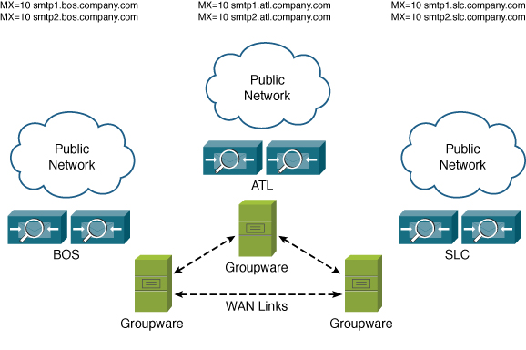
Figure 13-1. Organization with Multiple Locations and Equal-Priority MXs
In this case, it really doesn’t matter where the messages are received; after the recipients are validated and security filtering is done, each ESA delivers to its local hub transport server, which routes the message within the Groupware environment to the right mailbox server.
Unequal MX Priorities
There are several cases where primary-secondary or primary-secondary-tertiary MX priorities make a good deal of sense. For any organization that has more than one physical data center location, with one location acting as primary and others as subordinate, it makes sense to use MX records to direct the flow to the primary location, but make the subordinate locations secondary MXs.
Another architecture that calls for unequal MX priorities is for organizations that span countries and continents. For example, suppose your organization does business in the U.S. with substantial locations in Europe and Asia. The primary email domain for all users in all counties is domain.com, but you also have domain.de, domain.fr, and domain.cn, and DC locations in the U.S., Germany, and China.
Normally, all email to domain.com goes, via primary MX records, to servers in the U.S. and into the MS Exchange environment there. All messages destined to users outside the U.S. travels either to Europe or Asia, depending on where the user’s mailbox is. Email to the various country TLDs, like domain.de, goes directly to the Europe or Asia locations, as appropriate.
What happens if the MTAs in the U.S. location are down? By making the secondary MX records for domain.com point to Europe and Asia, messages could be accepted, and assuming WAN connectivity to the U.S. is intact, messages could still be delivered to the U.S. exchange servers. For the international domains, the secondary MXs can be set to the hosts in the U.S. In effect, the DCs in each location are a backup to each of the other locations:
domain.com. 86400 IN MX 10 usa.domain.com.
domain.com. 86400 IN MX 20 eu.domain.com.
domain.com. 86400 IN MX 30 asia.domain.com.
domain.de. 86400 IN MX 10 eu.domain.com.
domain.de. 86400 IN MX 20 us.domain.com.
domain.fr. 86400 IN MX 10 eu.domain.com.
domain.fr. 86400 IN MX 20 usa.domain.com.
domain.cn. 86400 IN MX 10 asia.domain.com.
domain.cn. 86400 IN MX 20 us.domain.com.
The drawback of using multiple MX priorities is that none of the systems other than the primary will receive more than a trickle of mail, unless the primaries are completely unavailable. ESA settings are by default designed to handle large fluctuations in traffic, to allow for natural spikes in connection volumes. In practice, this means that the primary MX systems can be extremely busy, with queue backups, but still available for new connections, while the secondary hosts see little to no traffic. This can be a risk for your email environment: Even in cases where the primary hosts are so busy that deep backups and long delays are occurring, Internet senders will generally not use the secondary.
Disaster Recovery (DR) Sites
Organizations that operate out of one or more primary data centers, but with one or more disaster recovery (DR) sites, should consider using MX records to reflect that. If the DR sites are truly that—to be used only in case of failures at primary locations—assigning secondary MX priorities to the inbound ESAs in those locations makes sense.
Third-Party DR Services
Several companies offer services that act as a “last line of defense” for email outages, accepting and holding Internet email if all MX hosts at your organization are unavailable. These services queue your email messages, and some even offer your users a means of accessing email while your environment is being restored. Upon restoration, the service provider will deliver the messages that were held during the outage.
Deployment of these third-party services is typically done through MX records. For example, take this list of hosts:
cisco.com. 86400 IN MX 10 smtp1.cisco.com.
cisco.com. 86400 IN MX 20 smtp2.cisco.com.
cisco.com. 86400 IN MX 30 cisco.drservice.com.
In the event of a failure of both of the first two hosts at cisco.com, the tertiary MX record would see all the connections.
Be aware of a few issues that can occur when using such a third-party service, and the configuration options you have to resolve them:
• Spammers tend to target MX record hosts other than the primary, so even when your hosts are up and running, the DR service is accepting messages, probably spam, for your domain. If they don’t perform any spam or virus filtering, or if their filtering is ineffective, they will redeliver spam and virus content to your hosts. Because you need to receive messages from the DR service, you must apply an appropriate HAT policy that ensures that connections are always accepted, but also runs spam and virus filtering on the messages. A further problem is that because the spam messages are delivered through a legitimate server, information about the original sender’s IP is lost, reducing the effectiveness of the ESA’s spam and reputation filters. The Incoming Relays feature can partially mitigate this, but it is difficult to configure in these situation because you need to know all the DR services’ IPs.
• If you are also using the DR service to deliver outgoing email to Internet destinations during an outage, you must account for this in SPF records and DKIM signing. You must add the DR service’s IPs to your SPF records. If they don’t support DKIM, but you want to sign messages, you must do so before delivery to the DR service.
• DR services may not offer TLS connection encryption and may not follow your established TLS policies with Internet senders and recipients. TLS only encrypts connections between MTAs, so although you can enforce TLS between your servers and the DR service, that encryption won’t extend to the next hop.
• DR services cannot typically offer LDAP integration for policy purposes. They may not offer DLP filtering or any other kind of content scanning, creating regulatory compliance risk during an outage.
In general, the needs for redundancy and disaster recovery often outweigh the disadvantages, but you should be aware of the risks.
Limitations of MX Records
Using MX records for failover and redundancy has its drawbacks. There are many reasons why MX records may not be adequate for your architecture:
• MX records cannot provide for fractional load splitting. Client behavior is to choose from equal-priority MX hosts at random, so if you have two at MX cost of 10, each will see half of the traffic; if you have three, each will see a third, and so on. If you want one server to get 50% of traffic and two others to get 25%, or other unequal split, MX cannot help you.
• MX records are more difficult to use for load balancing outbound mail to smarthosts.
• MX records require individual hosts. This means that each host must have its own public IP address, DNS A and PTR records, and possibly its own TLS certificate. Adding new hosts to the MX list might require allocation of new IPs, changes to DNS, and purchasing a certificate from a root certificate authority (CA).
• Load balancing among multiple hosts with equal priority isn’t perfect. Because various SMTP clients differ in how they pick among equals, load will be slightly higher on one of your hosts. Typically, the difference is not high enough to worry about, on the order of 5% more connections to one server than the others.
• MX records are not very dynamic. Like all DNS resource records, MX and A records for mail servers for a domain have a Time to Live (TTL) that varies, but is typically no shorter than 1 hour and often much longer, as much as 1 day or more. It is possible to make MX TTLs shorter, but even if you do so, many SMTP clients don’t actually honor the shorter times. This TTL problem means trouble if you need to quickly add or remove systems from your environment.
• Take care not to have too many hosts in your MX records, because of a problem with DNS resolution at many sites with large MX records. DNS is a protocol that requires both UDP and TCP, but UDP is used for the vast majority of responses. When the response is larger than the maximum UDP DNS payload limit of 512 bytes, it switches to TCP. That’s where the problem arises: In many environments, the use of TCP by DNS is not understood, and firewalls don’t allow the port 53 TCP connection. The result is that your MX record appears to not exist, and email can’t be delivered. It’s not really your problem, because the issue lies with the client’s DNS environment, but of course, when email can’t be delivered to your servers, it’s your problem.
Most email domains on the Internet today load balance through the use of MX records. With the transition to IPv6, MX records will continue to be the leading approach to load balancing and failover among email servers. If the limitations of MX records are showstoppers for your environment, consider hardware or software load balancers.
Dedicated Load Balancers
Dedicated software or hardware load balancers offer an attractive alternative to using multiple MX records. Load balancers can spread the load based on connection count, connection history, ESA system load, or other attributes rather than counting on the behavior of senders. Load balancers can also direct traffic unevenly—for example, diving the load across four ESAs in a 30/30/20/20 spread rather than the 25/25/25/25 that would result from fours hosts in an MX record. This is ideal if you have different models of ESA, or different data centers with different throughput capabilities.
Making changes to a load balanced environment is typically faster than dealing with MX records, as there is no DNS caching issues when you remove an ESA from the load balance pool.
With a load balancer, deploying ESAs is similar to a standard deployment, but the real IPs of the ESAs are not used in the MX records or smarthost settings. Instead, publish an MX record with a hostname that resolves to a virtual IP (VIP) on the load balancer:
cisco.com. 86400 IN MX 10 inbound.cisco.com
The VIP then distributes connections to the internal real IPs of the ESAs.
Load Balancers for Inbound Mail
Load balancers for inbound mail don’t give you any fundamentally new capabilities over MX record hosts, but they do give you more flexibility.
Configuring load balancing for ESA is much like configuring load balancing for any other server application, and should either round-robin SMTP connections, or use a least-load connection algorithm. Simple load balancers use only connection count to determine where to send the next connection, but if you have more advanced capabilities, like health checks or SNMP polling, you can use ESA attributes, like CPU usage and work queue count, to determine least-load ESA. In all cases, never use any kind of source Network Address Translation (NAT); the ESAs need to have the originating IP of the client preserved in the TCP connection in order to do accurate SenderBase reputation lookups. Per-host rate limiting and other sender controls also depend heavily on the true source IP being preserved on inbound connections.
For inbound connections from Internet SMTP clients, I recommend using load-balancer stickiness features, if available, to send repeated connections from the same source IP to the same destination ESA; this allows the ESA rate limiting to properly count individual clients and rate limit appropriately. Pure round-robin will result in each ESA enforcing its own limits and bad senders enjoying higher connection rates than they would otherwise.
If you’re using simple port 25 SMTP health check probes on the load balancer, make sure the connecting IP is granted a generous HAT policy on the ESAs, or you run the risk of rejecting or rate limiting these connections, forcing the load balancer to drop that ESA out of the pool.
The ESA configuration is not much different from any other deployment. It’s important to keep all the ESA configurations in a load-balancer pool synchronized, if for no other reason than troubleshooting: It can be maddening to track down a configuration problem when it’s only affecting some of your email messages or connections. You’ll even want to keep hostnames the same across the appliances to maintain the illusion of a single large host. Each ESA can maintain its own global hostname so that they can be distinguished, but the hostname assigned to the load-balanced real IP on each ESA should be identical, and it should match the external hostname of the VIP.
For example, suppose Cisco is using this MX record:
cisco.com. 86400 IN MX 10 inbound.cisco.com
It resolves to this IP:
inbound.cisco.com. 86400 IN A 128.107.234.204
This is a VIP in front of four individual ESAs: smtp1.cisco.com, smtp2.cisco.com, smtp3.cisco.com, and smtp4.cisco.com. All four of these ESAs should have a configuration that looks like this output from interfaceconfig:
Currently configured interfaces:
1. data (10.1.42.42/24 on Data 1: inbound.cisco.com)
Choose the operation you want to perform:
- NEW - Create a new interface.
- EDIT - Modify an interface.
- GROUPS - Define interface groups.
- DELETE - Remove an interface.
[]>
Keeping all four of the interface hostnames identical means that each ESA will use the same banner hostname during SMTP. This comes into play for TLS certificates and certificate verification, and for SPF verification of HELO domains.
Load Balancers for Outgoing Mail
The use of load balancers is especially appropriate for outgoing email, at the point in the architecture where your groupware or mailstore servers are delivering messages to the ESAs for delivery to Internet destinations. Most groupware servers have the ability to send messages to a “smarthost” that accepts email to all nonlocal recipients. This smarthost setting is often limited to a single hostname or IP address or to a list of hosts that have simple round-robin load balancing. For some systems, there is no load-balancing support for smarthosts whatsoever.
It is possible to use MX records for load balancing and failover of smarthosts. However, this requires that you publish a wildcard DNS entry for all nonlocal domains, with host records resolving to your ESA IP addresses. Any internal system needing to send email to an Internet destination does its own MX record lookup for the destination domain; your DNS server always returns the same values, regardless of the domain:
gmail.com. 86400 IN MX 10 esa1.company.com
gmail.com. 86400 IN MX 20 esa2.company.com
yahoo.com. 86400 IN MX 10 esa1.company.com
yahoo.com. 86400 IN MX 20 esa2.company.com
This approach is not usually easy, and depending on the DNS server, may not be possible at all. A hardware or software load balancer is the ideal solution for many of the same reasons previously listed for incoming mail.
Configuration of a load balancer itself is beyond the scope of this book, but many of the guidelines applied to incoming SMTP load balancing also apply to outgoing:
• Load balance based on least-load or round-robin of connections. If the load balancer offers health checks or other load determination features based on SNMP, use them. At the minimum, you should use port 25 health checks. On the ESA, you must whitelist the load balancer health check IPs to avoid rejecting or rate limiting these health check connections.
• Don’t use source NAT on connections from internal hosts. The ESA needs to see the connections from individual hosts in order to apply connection and rate limits on a per-host basis. NAT prevents the ESA from being able to distinguish individual internal hosts.
• Load balancers do their work by rewriting destination IPs, making it appear as if the client and server are directly communicating. To avoid asynchronous TCP connections, where the client sends connections through the load balancer, but the server responds directly to the client and to maintain original source IPs, the internal groupware and smarthost ESAs should be on different subnets. Ideally, the ESAs will be separated into their own subnet.
The last problem warrants an example. Suppose an Exchange server has IP 10.10.17.23/24, and you have three ESAs at 10.10.17.130–132/24. The load balancer VIP is 10.10.17.129. If the Exchange server initiates an SMTP connection to the load balancer VIP, the load balancer rewrites the destination IP to that of one of the ESAs. The ESA at 10.10.17.130 recognizes that the Exchange server is on the same subnet and replies directly, creating an asynchronous path. The Exchange server will drop the return packets. Moving the VIP to a different subnet won’t help because the ESA still thinks it should reply directly to Exchange.
The solution is to separate ESA from Exchange by changing the network settings or splitting that /24 network into at least two subnets. The other solution is to source NAT the Exchange server, but that will prevent the ESA from being able to distinguish from multiple internal hosts.
Multitier Architectures
I presented some of the many options for running multiple ESAs in parallel, where all devices are doing approximately the same job. All ESAs are handling inbound and outbound mail, all are security filtering, and all are delivering messages to their final destination whether internal or Internet. In general, this is my recommended architecture for deploying ESA—configuration is simple, and the architecture is flexible.
There are cases where separating ESAs into different roles can be of advantage. If your organization routes email between departments or organizations internally, for example, it doesn’t always make sense to send that mail through perimeter devices. For network security reasons, you may want to limit the access that perimeter ESAs have to internal networks or directories, requiring multiple layers of ESA.
Any cloud-based email security-as-a-service architecture will necessarily entail a multitier architecture: one tier at the service provider, which you may or may not have much involvement with; and a second tier at your premises, even if that tier only includes groupware servers.
There are drawbacks. As you might expect, multitier architectures are inherently more complex to build and administer. When carefully planned, performance should not be adversely impacted and in fact, some multitier architectures have higher average throughput than single tier. Message latency is increased with multiple hops, but not to a degree noticeable to human recipients.
Two-Tiered Architectures
Two-tiered architectures separate ESAs into two groups. The most common two-tier architecture has one group of ESAs facing the Internet directly and a second internal layer. The first layer, at the perimeter, handles incoming email from Internet senders and delivers outgoing messages to Internet destinations. Incoming email destined for local recipients is delivered to the internal ESAs for final delivery. Outgoing mail destined for Internet recipients is first delivered to the internal layer and then to the perimeter layer. Such architecture is shown in Figure 13-2.
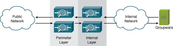
Figure 13-2. Two-Tiered ESA Email Architecture
There are a few reasons why you should consider using a two-tiered architecture:
• Internal messages stay internal: There’s no need to route messages to the perimeter if the source and destination are both internal. If you have multiple internal sources of email traffic, like application and web servers, in addition to person-to-person groupware traffic, ESA can perform the internal routing between these sources, forwarding all Internet messages to the perimeter.
• Load distribution: Handling some tasks on an internal layer of ESAs allows you to run fewer perimeter ESAs, making MX record management easier and conserving public IP space. For example, if you want to run two separate antivirus engines, running both on the perimeter systems requires more resources. Or you have a need to scan content for regulatory compliance. Moving one of the AV filtering tasks, or DLP, to an internal layer improves throughput on the perimeter layer, allowing fewer systems to handle the load.
• Limiting the scope of network access: General security practices dictate that perimeter devices should not have much, if any, direct access to internal systems. If you have need for extensive directory integration, or are transporting messages to and from other SMTP servers like encryption and DLP, you can perform these tasks on an internal ESA layer, keeping the perimeter layer limited in its access to SMTP with the internal ESAs.
I discuss some other two-tier architectures later in this chapter.
Three-Tiered Architectures
Email architectures can, of course, grow to an arbitrary number of layers, but for practical purposes, it’s recommended to keep it as simple as possible. In practice, the most complex email architectures within an organization are three-tiered environments.
A three-tiered architecture is only called for when business requirements dictate a hard separation of tasks for email filtering. An example of a three-tiered architecture is shown in Figure 13-3.
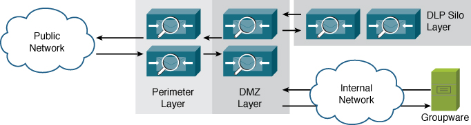
Figure 13-3. Three-Tiered ESA Email Architecture
A limited number of scenarios really call for a three-tiered architecture:
• Security requirements: Security policies in some organizations dictate that certain tasks, such as DLP or encryption reside on servers separate from security filtering, to allow specific policy officers to create rules and manage rule violations.
• Network requirements: Internal email tasks often require access to LDAP servers, DNS, or other resources that are only available internally. If your organization maintains separate resources internally, in the demilitarized zone (DMZ), and externally, and the ESA needs to access these, it must be placed on a network where the access will be granted. ESAs will happily span two or even three networks, but many environments don’t allow for servers to span across firewall borders.
• Multitiered DMZs: Strict access control between perimeter, DMZ, and internal can necessitate splitting the email environment into tiers to match.
I have helped companies design and deploy a few three-tiered architectures in my career, and although they solve some serious problems, their complexity means that they shouldn’t be used as a general-purpose approach.
Functional Grouping
Some environments call for separating ESAs into groups to accomplish different tasks or to separate administrative duties. These separate ESA roles allow configuration, access, storage, and delivery rules to be customized for each task.
A common example is separating Data Loss Prevention (DLP) and encryption requirements from the rest of the email flow, allowing policy administration and quarantined messages to be separately managed by a regulatory compliance team. These ESAs running DLP could be implemented inline or separately in a cul-de-sac model, which is described in Chapter 11, “Message and Content Filters.”
Another common architecture that groups ESAs by their role is separating incoming from outgoing email. Such architecture is shown in Figure 13-4.
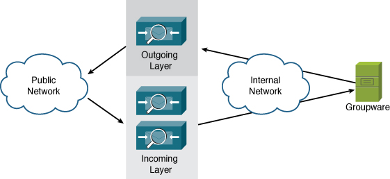
Figure 13-4. Separate Incoming and Outgoing ESA Roles
Separate incoming and outgoing roles are a popular ESA deployment architecture because it allows you to dedicate the right amount of resources to each task. Incoming email can be unpredictable due to the collective behavior of all Internet email senders. Outgoing mail traffic, although it varies over the course of the day, is much more predictable in terms of volume, connections, and message sizes. Separating the ESAs means that during periods of high-traffic incoming mail, outgoing ESAs don’t have to cope with the additional burden.
If you want to deploy separate inbound and outbound ESAs, there are a few recommendations:
• Anti-spam filtering of outgoing mail is usually unnecessary and ineffective, but I recommend applying antivirus filtering, with notifications to an administrator about outgoing viral messages. You need to be aware when an internal host is sending virus infected messages.
• Even if specific ESAs are intended for an incoming or outgoing role, you should configure all the ESAs identically so that they can be used for either. You may decide to collapse incoming and outgoing into a single role at some point. More importantly, when all ESAs are prepared for either role, you can change the role of any ESA to deal with changing traffic volumes. If the outgoing ESAs are handling all traffic with plenty of headroom, you may decide to move an ESA to the incoming role. Centralized Management features make this configuration simple.
• Don’t restrict the access of the incoming layer to send outgoing SMTP messages. Even though they might be dedicated to incoming messages, they will still have the need to deliver delivery status notifications (bounces), notifications, or reports. Restricting them also makes it harder to redeploy as outgoing servers.
Aside from separate incoming and outgoing groups, some other examples of ESA grouping by functional roles include
• Dedicated DLP layer: Message scanning for sensitive content or regulatory compliance can be performed using the DLP Policy features on the ESA. Segmenting this filtering on a separate layer allows for delegated administration, tracking, and storage of DLP violation messages.
• Segmenting bulk and normal traffic types: The traffic from individual users to remote, typically passing through the ESAs from the groupware servers, is handled by one set of ESAs, while bulk, machine-generated messages are handled through another set. Separating traffic onto separate servers can provide the appropriate horsepower for each task, and prevents high-volume bulk mailings from interrupting important person-to-person traffic. Using separate ESAs, with their own IPs and hostnames, also restricts any damage from blacklisting. If your organization does marketing, order updates, account statements, or other automated messaging, you should consider segmenting.
• Dedicated “private mail” layer: Many organizations send and receive mail over private links when dealing with subsidiaries or partners, for security purposes. These links may be dedicated circuits or VPNs, and may be used for other traffic besides SMTP. Although this trend is on the decline thanks to the use of TLS for secure message transmission, it’s still common to find these private links in use. A dedicated ESA can direct traffic as needed over these private links for any mail sender in the organization.
Large Message Handling
One last example of ESA grouping is large message handling. During the course of the day, SMTP traffic volumes fluctuate in both number and message sizes. When you size an ESA environment correctly, you have enough horsepower to handle even peak message volumes at average message sizes. One factor that makes performance difficult to predict is large messages: They drive up average message size and take significantly more resources to process, even though they typically make up a very small number of the total message count.
The result is that a system that is comfortable handling thousands of messages per minute with little latency can become temporarily backed up while it processes a few large messages. What we want to do is to make the impact of large messages more predictable and avoid backing up hundreds or thousands of small or moderate messages just because a couple of large messages are being scanned.
Take this example of an organization’s message size and volume spread in Table 13-1.
Table 13-1. Message Size and Volume Distribution in an Enterprise
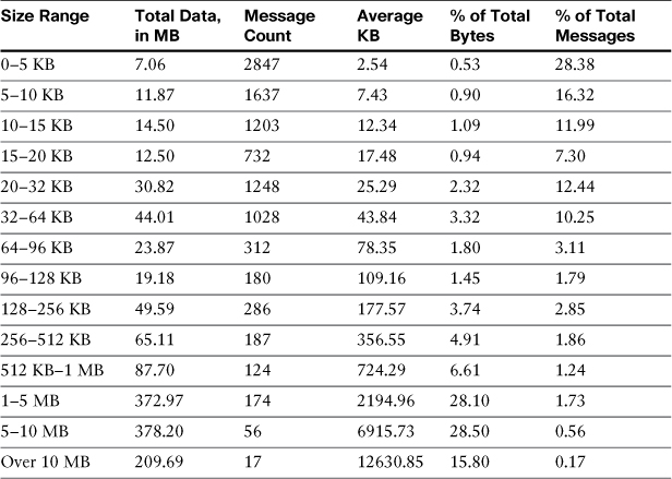
Table 13-1 shows an enterprise count and volume spread that is very typical. The two rightmost columns, percentages by total bytes and percentage by message count, show that most of the messages (by count) are very small in size; but, most of the bytes come from a very small number of large messages. If we can do something about these large messages, we can make average throughput much higher, and much more predictable.
I make the assumption that you’re not allowed to set your message size limits very low! Instead, my suggestion is to move these large messages to a different server. Once they’re accepted at the perimeter, don’t do any kind of filtering on them whatsoever, but send them to another host and move them immediately to delivery. The only overhead incurred is the transport of bytes, which is trivial compared to the scanning effort. A simple message filter can perform the redirection:
large_message_offload:
if (body-size > 64KB) {
alt-mailhost ("largemessage.domain.com");
skip-spamcheck();
skip-viruscheck();
skip-vofcheck();
skip-filters();
}
Of course, also take care with content filters in the web user interface (WUI), where you should create similar logic to bypass all the filters there. Remember that the message filter action skip-filters does not affect the content filters engine later in the pipeline. Where should you send your large messages? To another group of ESAs dedicated to large message handling. A conceptual diagram of an ESA architecture segmented by size is shown in Figure 13-5.
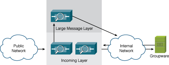
Figure 13-5. Large Message-Handling Architecture
This message segmenting results in message latencies that generally match user expectations: Small messages are delivered quickly no matter what, so rapid back-and-forth email discussions aren’t interrupted. Large messages are handled as quickly as they can be, with a minor addition to latency, but users typically don’t have the same expectation for quick email delivery on messages over 1 MB. It’s akin to moving heavily laden tractor trailers to a slow lane on the expressway; the tractor trailers still get there in about the same amount of time, but the passenger cars can breeze right by.
The message size redirection point is up to you, but it should be somewhere so that you are still processing most of your messages on the primary ESA layer. I’ve seen good results in practice in places where we’ve processed 50–90% on the perimeter ESA layer, sending the remaining to the large message farm. I picked 64 KB in this example, because that covers 85% of the total message count. Using 32 KB would still cover 75% of the total message count and improve performance on the perimeter layer further.
Architectures with Mixed MTA Products
The modern architecture separation between perimeter email security and internal email groupware and message store means that most organizations will have more than one vendor’s products handling SMTP. Some organizations have multiple products from different suppliers in the email architecture, typically for specialized function at each step in the processing chain.
Some environments have a temporary need for multiple products. If you’re evaluating ESA to replace another MTA server, you will likely be running both in parallel for some time.
If you need to incorporate third-party products for encryption, archiving, or DLP, this section will describe some deployment strategies and the ESA configuration required to support them.
Integration with External Systems
The primary challenge with integration of disparate SMTP systems is that they typically only have SMTP in common. There is no clearly established practice for sharing data across MTAs, and no standard protocol for transporting message data other than SMTP itself. Even with those limitations, though, you can build a reliable environment that incorporates other types of SMTP servers with the ESA.
As discussed in Chapter 11, when describing filters and routing to incorporate external SMTP servers into an ESA environment, there are two primary approaches:
• Inline: All messages are delivered from one server to the next, in order. For incoming traffic, this usually means ESA to external server and then to groupware. For outgoing traffic, the path is usually groupware to external server to ESA for final delivery.
• Cul-de-sac or “out and back”: ESA handles all incoming and outgoing messages, but redirects some or all to the external server for handling. The external server redelivers any resulting messages back to the ESA for final delivery.
Of the two, I typically recommend using the cul-de-sac model, because the external server is often not designed for high volumes and high throughput, and in most cases, typically doesn’t need to act on all messages. The ESA can act as the traffic cop, directing messages to the external server as appropriate.
External Email Encryption
Email encryption refers to encrypting the SMTP transport, or encrypting email message content, attachments, or providing a secure means of retrieving message content. The ESA has supported Transport Layer Security (TLS) for SMTP since its inception. Because TLS is not uniformly available and does not provide encryption all the way to the end user’s MUA, Cisco has offered an email message encryption feature called envelope encryption.
If you’re using envelope encryption features on the ESA directly, this section isn’t for you. If you’re using envelope encryption or other message encryption features on the IronPort Encryption Appliance (IEA) or other external encryption server, the architectures here apply to your environment.
We categorize encryption solutions into a few main types:
• Secure “pull” solutions: These encryption solutions generally accept messages and store their contents in an encrypted database or filesystem, and allow end users to access their secure messages through a secure web (HTTPS) connection. When messages are stored, the encryption server generates a notification to the original recipient, informing them of the secure message and providing an HTTPS link. The encryption solution may also include authentication via web-based form login. The advantage of this model is the simplicity for the end recipient, although it does require that you provide storage, redundancy, and public availability to the encryption server.
• Secure “push” solutions: The message content and all of its attachments are encrypted using well-known ciphers, like AES, and the resulting encrypted data is packaged up and sent to the original recipient. The challenge these solutions have is packaging the data so that the end user can open it. Many solutions require the recipient to have or install some software for this; the Cisco Envelope Solution uses the recipient’s web browser as the decryption platform, so the user doesn’t have to download or install other software. For the user, this model is convenient and easy to open provided he has a web browser. For you, the sender, the advantage is that it doesn’t require local storage at all; once the message is encrypted, the encrypted package is sent to the recipient.
• Public/private key pair encryption: These solutions use private/public key pairs to encrypt the content, usually based on knowing the recipient’s public key. As with all PKI systems, the challenge is in the key management. These solutions also typically require software on the client to encrypt and decrypt messages.
Regardless of the encryption method and recipient access model, using an external encryption server generally works like any other external server. Policy dictates when messages should be sent for encryption:
• User initiated: The user indicates in the message that it should be encrypted before delivery. This can be a subject-line string, a marker such as message sensitivity recorded in a header, or even text contained in the body of the message.
• Sender/recipient based: Your organization may have requirements that all email to specific third parties be encrypted or that all messages from certain groups, such as legal or accounting, be encrypted. This could be based on static address or domain lists or tied to LDAP grouping queries.
• Content scanning initiated: Encryption can be an action taken based on DLP policy or other message-body and attachment content scanning. For example, a DLP policy for payment-card industry data security standards (PCI-DSS) might encrypt messages based on the presence of a credit card number with an expiration date, whether the sender wanted the message encrypted or not.
Deciding on the policy is the hard part; the ESA can implement filters to enforce the policy or even to establish a workflow forcing users to follow the encryption guidelines. Of course, the ESA can also enforce multiple policies, and it is typical to provide both “user initiated” and “content initiated” encryption.
Here’s an example of a filter configuration for an external encryption server, based on the subject starting with the string [ENCRYPT]. We begin with a short circuit, bypassing any further processing of messages that come from the encryption server. Message traffic from the encryption server could be encrypted content, or notifications to recipients about encrypted messages. If the contents are encrypted, there’s not much the ESA could do with them, anyway. Then, we redirect messages based on the subject test:
encryption_short_circuit:
if (sendergroup == "ENCRYPTION") {
skip-filters();
}
encryption_redirect:
if (subject == "(?i)^[ENCRYPT]") {
alt-mailhost ("encryption.domain.com");
}
External Data Loss Prevention (DLP) Servers
Scanning email messages and attachments for the purpose of identifying confidential, sensitive, or regulated content is an established and growing need in most organizations. Cisco introduced Data Loss Prevention (DLP) filtering for email on the ESA with AsyncOS 7.0 in 2010, but many customers have deployed a dedicated DLP solution, one that handles SMTP email but also web, instant messaging (IM), databases, and document file servers.
The subject, for this section, is how to integrate an external SMTP DLP server with an ESA environment. We discuss the built-in DLP solution in Chapter 15. The ESA only supports SMTP transport of message data, so you cannot use other protocols, such as ICAP for DLP integration.
Like all the other third-party server integration we’ve seen, DLP servers can be incorporated through SMTP in two fundamental ways: inline, where messages pass from one server to another in the delivery path, and cul-de-sac, where the ESA controls the messages “out and back” to the DLP server.
External DLP starts with a message or content filter redirect that looks a lot like the encryption solution from the last section. In fact, we can start from basically the same message filters. In this case, I assume that you want to send all content to DLP:
dlp_short_circuit:
if (sendergroup == "DLP") {
skip-filters();
}
dlp_redirect:
if (true) {
alt-mailhost ("dlp.domain.com");
}
In encryption, we’re not expected to do much on the ESA with the traffic returned from the DLP solution, because the messages are either encrypted content or notifications to recipients about encrypted content. DLP, however, could be different, because the ESA can act as the point of enforcement when the external DLP solution discovers a violation.
If you want the ESA to act as the enforcement point for DLP violations, the DLP server has to have some means of indicating which messages violate policy. A common technique is to use a message header added to messages that contain a violation. ESA acts on the presence or value in a header:
dlp_short_circuit:
if (sendergroup == "DLP") {
if (header ("X-content-scan") == "(?i)violation") {
quarantine ("Policy");
notify ("[email protected]", "DLP Policy Violation",
"$EnvelopeFrom", "dlp.notify");
}
skip-filters();
}
dlp_redirect:
if (true) {
alt-mailhost ("dlp.domain.com");
}
The header name is arbitrary, as are the values. ESA is only looking for a string match. If the DLP engine is scoring a message with a numeric score, the ESA can’t directly make comparisons on the numeric value. However, we can play some tricks with regular expressions to do numeric matches. Suppose the DLP solution will score a message from 0 to 100, writing the value into a header called X-policy-severity, and you’re interested in stopping messages that score 70 or higher. This filter condition finds all the two-digit severities above 70, or 100:
if (header ("X-policy-severity") == "([789]d|100)")
Email Archiving Servers
Another common integration point is with email archiving solutions that store a copy of all messages to meet records retention requirements. There tend to be two approaches to archiving: direct integration with the groupware and a standalone solution. Email archiving solutions that are directly integrated with your groupware servers storing copies of messages sent and received by users—anything that passes through the groupware. For messages that don’t pass through the groupware, such as application-generated messages, other arrangements must be made. Standalone systems typically require that copies of email messages be sent to the archiver by all servers that transport or store enterprise email.
Whether standalone or groupware integrated, you likely will have a need to direct copies of messages passing through the ESA to an archiver. There are a couple of approaches, depending on your need. The first approach is archiving inline or cul-de-sac, treating the archive SMTP server as we would treat an external DLP or encryption solution. The other approach is to simply send message copies, using a BCC or notify filter action, to the archiver, allowing the original message to pass through unchanged.
Archiving Inline or Cul-de-Sac
It’s a common approach to treat the archiver as just another third-party server in the ESA architecture. The same filter rules that were discussed earlier can be used to route messages to and receive messages back from the archiver. An inline model is simple: The incoming email path is ESA to archiver to groupware. Outgoing is the exact reverse: Groupware to archiver to ESA. The inline model is less than ideal, however, because most archivers have limited MTA capabilities (if any) and are not designed for the high throughput that the ESA delivers.
The cul-de-sac or “out and back” model is more appropriate for archiving, because the ESA controls the message path. The ESA in this model gives you some flexibility in determining whether messages should be sent to the archiver.
It makes little sense to send messages to the archiver if the message has already passed through it. In those cases, some HAT sender group and filter magic can save us the work. These filters show an ESA redirecting messages to the archiver, only if they did not come from one of the groupware servers. The assumption is that the archiver is integrated with the groupware servers and already has a copy of those messages:
archive_short_circuit:
if (sendergroup == "ARCHIVE") {
skip-filters();
}
archive_non_groupware_messages:
if (sendergroup != "GROUPWARE") {
alt-mailhost ("archive.cisco.com");
skip-filters();
}
These actions don’t have to be done in message filters, and can be done in content filters. In fact, doing so after spam filtering can avoid the archiving of junk messages. The filter can also be applied to specific sender groups, email addresses, or LDAP groups. Any filter logic available on the ESA can be used in deciding what is and what should not archive. My experience with enterprise email environments tells me to err on the side of caution: It’s better to archive too much and have duplicate copies of some messages than to miss any messages.
Archiving Through BCC
Archiving is not like DLP or encryption, where we expect that the message contents returned to the ESA will be different than what was sent. We expect to see exactly the same message contents back from the archiver in any kind of inline or cul-de-sac model. So, why bother sending the message there for delivery? Why not just send a copy of the message?
Most archivers support receiving messages addresses to a specific email address at a hostname. Given this, we can write a simple archiving message or content filter:
archive_all:
if (true) {
bcc ("[email protected]", "$Subject");
}
When it encounters the BCC action, ESA creates a new message with the BCC address as the sole envelope recipient. The new message is identical to the original in other respects.
This is an ideal solution except for one problem: Because the BCC copy only includes the archiver address as envelope recipient, the original envelope recipient list is lost. This is fine if all the envelope recipients are also listed in the To and CC headers. To and From headers are preserved in the BCC copy, as all other message headers are. But, if the original message already had one or more BCC recipients (that is, envelope recipients NOT represented in the To and CC headers), they will be lost in the BCC copy.
If you must archive the message with all the original envelope recipients—whether or not they also appear in To or CC, you must add the original envelope recipients to another header, like this:
archive_bcc_all:
if true {
insert-header("X-rcpt-to", "$EnvelopeRecipients");
bcc ("[email protected]", "$Subject");
}
Now, listing the envelope recipients in a message header defeats the point of a blind carbon copy, because any recipient smart enough to look in the headers will see the original recipient. You can strip this off the original message without affecting the bcc with a simple addition:
archive_bcc_all:
if true {
insert-header("X-rcpt-to", "$EnvelopeRecipients");
bcc ("[email protected]", "$Subject");
strip-header("X-rcpt-to");
}
Because the BCC exits the filter processing at the point of the action, the message copy sent to the archive will still have the X-rcpt-to header intact. The original message will have the header removed by the last strip-header action.
Other Archiving Ideas
The normal enterprise requirement for archiving is, obviously, that messages are permanently stored for compliance. What drives product selection in this area, though, is typically the other side of archiving, that of management and discovery. The entire point of most compliance-driven archiving requirements is that the archived messages be easily searched for and retrieved when necessary.
On the other hand, in some environments, there’s really little need for discovery. Sometimes, message archiving is just for disaster recovery or troubleshooting. If you’d like to keep a copy of messages on-hand, there’s a way to do so with the ESA’s message filters. The archive action writes a plain-text copy of the message data verbatim. For example, if you want to keep a copy of all messages sent to a particular recipient, this filter accomplishes that:
archive_rcpt:
if (rcpt-to == "chriport@cisco\.com") {
archive ("rcpt");
}
How does the ESA store these messages, and where? By creating such a filter, the ESA automatically creates a log subscription where the files are created. Unlike other log subscriptions, this one is not managed through the WUI page or the CLI logconfig command; rather, it’s managed in a new menu option in the filters command called logconfig:
esa02.cisco.com> filters
Choose the operation you want to perform:
- NEW - Create a new filter.
- DELETE - Remove a filter.
- IMPORT - Import a filter script from a file.
- EXPORT - Export filters to a file
- MOVE - Move a filter to a different position.
- SET - Set a filter attribute.
- LIST - List the filters.
- DETAIL - Get detailed information on the filters.
- LOGCONFIG - Configure log subscriptions used by filters.
- ROLLOVERNOW - Roll over a filter log file.
[]> logconfig
Currently configured logs:
1. "rcpt" Type: "Filter Archive Logs" Retrieval: "Manual Download" Retrieval
Interval: "None"
Choose the operation you want to perform:
- EDIT - Modify a log setting.
[]>
You have the same options for this log subscription that you would for any other log: file size, file count, rollover schedule and various file transfer options to automatically move logs to another server. You can use CLI log commands like rollovernow, tail, and grep on these archive files. Because the ESA has limited storage space for logs, if you want to keep a permanent archive, you must move the logs to another server.
When a message is written to disk, it uses a plain-text format for message data usually called mbox format, after the name used by a number of UNIX MUAs and transports to store a user’s mailbox. It’s essentially the exact same text as was injected in the SMTP data command, but with the SMTP MAIL FROM written as the first line of the archive:
From [email protected] Wed May 18 16:11:16 2011
Received: from host101.domain.com (HELO [192.168.1.5]) ([192.168.1.5])
by mail.chrisporter.com with ESMTP/TLS/DHE-RSA-CAMELLIA256-SHA; 18 May 2011
16:11:16 -0400
Message-ID: <[email protected]>
Date: Wed, 18 May 2011 16:11:16 -0400
From: Chris Porter <[email protected]>
User-Agent: Mozilla/5.0 (Macintosh; U; Intel Mac OS X 10.6; en-US; rv:1.9.2.17)
Gecko/20110414 Thunderbird/3.1.10
MIME-Version: 1.0
To: Chris Porter <[email protected]>
Subject: Cisco IronPort ESA
Content-Type: text/plain; charset=ISO-8859-1; format=flowed
Content-Transfer-Encoding: 7bit
Simple message text.
A blank line is used as the delimiter between messages. All attachments are written in their plain-text encoded MIME format.
Introducing, Replacing, or Upgrading ESA in Production
Whether you’re introducing ESA into your environment for the first time, or upgrading or replacing an existing ESA, you will find yourself occasionally facing the task of bringing a new ESA online and putting it into production.
Adding the First ESA to the Environment
For the first ESA that you’re installing, you’ve hopefully read through the earlier parts of this book, including basic system setup and establishing security filtering and directory integration. I assume that, at this point, you have a running ESA with a tested configuration. The ESA is either on a publicly routable IP with a world-resolvable hostname or an internal IP with NAT to such a public IP.
There are a few options for introducing an ESA into an environment where other products are already running:
• Adding the ESA’s external hostname to your current MX record as a lower-priority host. By adding the ESA as a secondary MX, you can introduce a bit of production traffic without interrupting normal mail flow. As secondary, the ESA will only get a bit of junk traffic, but you can see how the ESA runs in production. This will allow you time to gain familiarity with the product, use the reporting, tracking, and troubleshooting tools with live traffic, and verify the initial ESA configuration.
• Adding the ESA’s external hostname to your current MX record as a primary host. This can be done either as a first step or as the second step after Step 1. Remember that changing MX records is not an immediate change; you have to wait for SMTP clients to expire their cached DNS entries and lookup the new record.
• Adding the ESA into a load-balanced pool. If you are using a load balancer, adding the ESA into the pool will give you precise control over how much traffic is initially sent to the ESA.
• Direct replacement of an existing server. This approach is fast and quick, but requires some juggling. If you intend to replace an existing host by giving the ESA its IP address and hostname, you’ll have to do some cable-swapping or switch port manipulation in the DC, because both hosts cannot be online with the same IP at the same time. I generally recommend configuring and testing ESA with another IP until you’re ready for the swap. It’s a good idea to suspend the ESA listeners until network connectivity is confirmed. Some switches can take a while before they notice the change and update MAC address tables. Any kind of switch port MAC security can cause a port to be disabled if the connected device is changed.
• Inline with the existing solution. ESAs can be run in a tiered fashion in front of or behind the existing solution. This approach has a number of drawbacks, not least of which is the complexity of a two-tiered solution of different products. If you need this “belt and suspenders” approach during a transition period, I recommend putting the ESAs on the Internet-facing side, because the security filters are severely hobbled when receiving messages from another internal host.
Whichever method you choose, remember that the change affects not only the email administrators, but also all the end users. To avoid surprise, it’s a good idea to provide plenty of notification about the change.
Replacing an ESA for Upgrade
At some point, an individual appliance in your environment will likely require replacing. Reliable as ESA is, computer hardware can experience failures. Or you may be upgrading your appliances to handle more message capacity, or running advanced applications like encryption or DLP. Whatever the reason, replacing an ESA with a new unit is straightforward if you follow a few simple steps. I assume that you want to remove an existing ESA and replace it with another that has the exact same configuration.
Cisco ships ESAs running an AsyncOS release known as the MR (Manufacturing Release) version to customer on new orders. The MR version changes over time as Cisco updates AsyncOS. This MR version is usually somewhat behind the current available GA (General Availability) or FCS (First Customer Ship) versions that you can install using the ESA upgrade features. In all likelihood, you will need to upgrade any newly shipped appliance to match your existing ESA environment. It’s a good idea to run ESAs at the same software version; it’s a hard requirement for ESAs in a centralized management cluster.
If you are normally conservative about upgrading the ESAs, and your production servers are running a release more than a year old, the MR version on new appliances may actually be newer than the release you’re running. If you want to avoid upgrading all of your production appliances to a later release, you can request that Cisco ship an older version of software on the appliances. It is not possible to downgrade a newly shipped ESA. Be aware, however, that if hardware models have changed, the new hardware will have minimum software level requirements. You can’t run AsyncOS 6.5 on a new C670 model, for example. The C670 hardware is first supported in AsyncOS 7.0 software.
Any ESA hardware faults, alerts, or outright failures should start with a call to Cisco’s IronPort support; you cannot return ESA hardware without a Returned Materials Authorization (RMA). Assuming you have an RMA or are just going to take the system out for other reasons, the next step is to remove the ESA from the production traffic flow:
1. Suspend the listeners on the ESA using the CLI command suspendlistener, or the WUI page at System Administration → Shutdown/Suspend. Do not suspend delivery. The ESA will gracefully close existing connections after they have finished and not accept any new ones. Run the delivernow command to force the ESA to make another attempt to deliver all messages. You can use the commands hoststatus and status detail to determine when all the messages have been delivered.
2. Export a configuration file using the CLI command mailconfig or the WUI page at System Administration → Configuration File. You must deselect the option to mask passwords, or answer N to password masking. Configuration files with masked passwords cannot be used to restore an ESA configuration. If you’re using the end-user quarantine Safelist/Blocklist feature, you must export this table separately.
3. Release or delete any important messages from the system quarantines using the WUI page at Monitor → Quarantines. If the messages are unimportant, you can leave them, but you may want to delete them before returning or disposing of the appliance. For messages stored in the spam quarantine, you can release them to end users or delete them. I suggest browsing through the recent additions to the quarantine to release any false positives, and then delete all the messages.
4. Retrieve any other important data from the ESA: reports, logs, or older configuration data. We will restore the configuration values from all the tables in the ESA, but log files and other data stored on the appliance filesystem are not part of configuration.
Note that I didn’t list a step of removing the ESA from MX records or load balancer pools or anything else; if you are using either of these recommended methods to balance SMTP connections, you won’t need to. SMTP MX rules will allow clients to connect to other hosts listed in the MX record, and load balancers will recognize the unavailability of the ESA and stop directing connections to it. The ESA will not accept new connections after the suspendlistener command has been issued.
After the system has been “draining” for some time, there may still be messages in the delivery queues. You have a few options here: examine the messages in the queue and then either bounce them, delete them, or redirect them to another SMTP server, including another ESA. Typically, the messages in queue after more than a few hours are probably never going to be delivered at all. It’s often misdirected bounces, mistyped recipients, or other unimportant messages.
To examine the messages in queue, you’ll have to switch to the CLI and use commands like tophosts, hoststatus, showrecipients, and showmessage to examine the queues and messages in them. To delete individual messages by MID, you can use removemessage; to delete messages by sender address or recipient domain, you can use deleterecipients.
If there are a lot of NDRs (non-delivery records or bounces) and other less important messages, you can just use deleterecipients to remove all of them. Obviously, this is dangerous. bouncerecipients is slightly less dangerous; bouncing NDRs causes a “double bounce” and drops them, but any other messages are returned to the sender.
If there are a lot of messages in queue that you want to preserve, you can send them to another system, including another ESA, using the redirectrecipients command or by changing the default route in the SMTPRoutes table. Remember that the other ESA must list the ESA you’re replacing as a RELAYLIST host so that it accepts the messages.
At this point in the process, you have an ESA that is not accepting new connections and has no active messages in any queue, including the quarantine. Any sensitive data, like logs or old configuration files, are deleted. You are in possession of an up-to-date configuration file. You can shut the old ESA down using the shutdown command in the CLI or using the System Administration → Shutdown/Suspend page in the WUI.
You’re ready to install the new appliance. Following the guidelines for setup in Chapter 2 (WUI) or Chapter 5 (CLI), run the System Setup Wizard to get the configuration basics on the new ESA. You don’t need to provide complete data for all the tables and settings, as we are next going to restore the configuration from the old ESA. What’s important here is getting the network configuration right and enabling the security filters and accepting their license agreements.
Before you put the new ESA on the network, suspend the listeners using the WUI or CLI. A new appliance with even a basic configuration will have an active listener and begin accepting connections.
Once you have the new ESA up and functioning on the network, here are the steps to restore the configuration:
1. To make the configuration restore easier, the new ESA should be on the same version as the old ESA. Often, importing an older configuration into a new AsyncOS version will work fine, but newer configurations won’t import into older versions. It’s best not to take a chance; if the old ESA was running 7.1.1-101, you should match that in the new version.
2. If the new ESA has an identical network configuration to the old, including IP address and hostname, continue to Step 3. If not, you have two choices: Edit the XML configuration file and change these values prior to import. Or, when you get to Step 3, change the IP address and hostname after the import, but before you commit the change.
3. Import the configuration file using the WUI’s System Administration → Configuration File page. If you get an error on the import, the error message will include the line number and element name where the first import error occurred. This should only happen if you modified the configuration file and made an editing mistake or you’re trying to import a configuration from a newer or older AsyncOS version. You can try to correct the mistake and import again.
Once you import the configuration, but before you commit the change, examine the settings in the WUI to be certain the settings are accurate, especially the network settings. Commit the change to finalize the configuration.
To resume the operation of the system, run the CLI resume or resumelistener command, or use the Shutdown/Suspend page in the WUI.
Management of Multiple Appliances
In all the discussion of deploying multiple appliances, I skipped over the assumption that they will all need to be managed. In most cases, I’m in favor of deploying ESAs in a flat, single-layer architecture with all appliances configured identically. Regardless of the deployment model, you will have two or more ESAs to manage.
The Cisco IronPort Centralized Management (CM) feature is ideal for managing multiple appliances in clusters as large as 20 ESAs. For four or more appliances, it’s imperative that you use this feature, not just because it’s tedious to make the same configuration on multiple machines, but that it’s impossible to be 100% consistent in making those changes on every ESA, every time; eventually, you will end up with configurations out of synch.
The only alternative to using centralized management would be a process of exporting and importing configurations across multiple ESAs. In practice, this isn’t terribly time consuming, but it is more effort than using centralized management (CM). Because an ESA configuration file contains host-specific network information, such as IP address and hostname, the configuration files need to be edited for each target machine. These settings are grouped near the beginning of the XML configuration. This process of export, edit, and import can even be automated using configuration scripts on an external system in a scripting language, like Perl or Python.
Centralized Management Overview
The centralized management (CM) feature synchronizes configurations across multiple peer ESAs organized into a “cluster.” No single device in the cluster is considered a master configuration; changes made on any system in the cluster are communicated in a peer-to-peer fashion to all the other systems. It provides robust error handling, allowing for the update of machines that have been temporarily disconnected from the cluster.
In addition to keeping configurations synchronized across multiple ESAs, CM makes adding and removing ESAs from the environment easy. To add a new ESA, simply configure it for the network, and add it to the cluster. It automatically picks up configuration settings from the other machines.
Cisco uses the term cluster to define a group of ESAs linked through the CM feature; it’s the top-level taxon in a CM hierarchy. I refer to clusters and clustering throughout this section and everywhere else where CM is discussed in this book.
It is important to understand that this term does not refer to any kind of load balancing or failover features. In the industry, clustering usually refers to multiple physical servers sharing IP address information, combined with monitoring and failover capabilities. This is not what ESA clustering refers to; it is purely a configuration synchronization feature.
CM doesn’t provide centralized reporting, tracking, or quarantines; no form of data or logging is centralized. Per its name, CM is strictly limited to configuration data.
To use CM, all the ESAs must be able to communicate with all the others, typically via SSH. For systems on the same subnet or neighboring subnets connected only by a router, this should not represent much of a problem. For ESAs separated by network equipment, like firewalls, you may have to account for the SSH traffic by opening firewall rules.
Creating a CM Cluster
Creating a cluster must be done from the CLI command clusterconfig. This command is only available if you have a valid, active CM feature key installed on the ESA. When you run it for the first time, you’re given a short list of options:
esa02.cisco.com> clusterconfig
Do you want to join or create a cluster?
1. No, configure as standalone.
2. Create a new cluster.
3. Join an existing cluster over SSH.
4. Join an existing cluster over CCS.
Choose 2, “create a new cluster,” to start the configuration process. You are prompted for a name for this cluster, which is a friendly name that identifies the entire environment. Use a name that’s appropriate, like Perimeter or Inbound. If you have more than one cluster planned, appropriate naming is important.
Next, you have the choice of communicating by IP addresses or by hostnames. If you have proper DNS A records for the interfaces you want to use CM on, go ahead and choose the hostname option. If you’d rather not have a dependency on DNS, or DNS for the ESA’s IPs is not available, choose IP.
At this point, the ESA creates the cluster and add the machine to it. That’s all there is; you don’t need to commit this change. From now on, whenever you commit configuration changes, notification is sent to all machines in the cluster about the changes. Each machine is responsible for applying the appropriate configuration changes.
Joining an Existing CM Cluster
Once you have a cluster created using the previous steps on a single ESA, you need to add additional machines to the cluster. Clusters of single ESAs aren’t interesting. On the ESA to be added, you need to run clusterconfig and choose option 3 or 4 to join the cluster:
esa03.cisco.com> clusterconfig
Do you want to join or create a cluster?
1. No, configure as standalone.
2. Create a new cluster.
3. Join an existing cluster over SSH.
4. Join an existing cluster over CCS.
[1]> 3
While joining a cluster, you will need to validate the SSH host key of the remote
machine to which you are joining. To get the public host key fingerprint of
the remote host, connect to the cluster and run: logconfig -> hostkeyconfig ->
fingerprint.
WARNING: All non-network settings will be lost. System will inherit the values
set at the group or cluster mode for the non-network settings. Ensure that the
cluster settings are compatible with your network settings (e.g. dnsconfig
settings)
Do you want to enable the Cluster Communication Service on esa03.cisco.com? [N]> n
Option 3 tells the system to join using SSH, which defaults to using the same standard port 22 SSH that you’re probably logged into the CLI with. Option 4 uses the Cluster Communication Service, CCS, which is still SSH under the hood, but uses a nonstandard port for SSH that doesn’t allow interactive (username and password) configurations. Unless you plan to completely disallow remote logins with SSH to your ESAs, the extra flexibility of CCS is usually not necessary. Because it requires another port to be opened between all of your ESAs, I recommend against using CCS.
The process continues by prompting you for the IP address and port of a machine in the cluster. It doesn’t matter which other machine, as long as it’s a cluster member. You’re prompted for the “admin password of the cluster,” which is the password of the admin account on the other machine, and which is a one-time event. Joining a cluster involves establishing SSH keys between systems for secure connections without passwords:
Enter the admin password for the cluster.
Please verify the SSH host key for 10.92.152.28:
Public host key fingerprint: b9:c3:8d:bc:3f:91:2e:d7:3b:3e:88:75:0e:2f:1c:7d
Is this a valid key for this host? [Y]>
If there is more than one group in the cluster, you are prompted to choose a group to join:
Choose the group to place this machine in.
1. PHL
2. SFO
[1]> 1
After that, the ESA finalizes the process and applies the CM configuration. There’s no need to commit this change.
Creating and Managing CM Groups
Within a cluster, you can configure one or more CM groups. A group is a subset of cluster members that have some settings that differ from other groups or from the cluster. All ESA machines in a cluster are members of a group. Even in a new cluster where no groups have been configured, the default group called Main_Group is created for you.
Every configuration setting on the entire ESA exists at machine, group, or cluster mode. In a new cluster, there are sensible defaults for what mode the settings exist at. Listeners default to cluster mode. IP interfaces default to machine mode. When you’re using the CLI or WUI to manage the ESA, your administration interface changes to reflect the mode you’re currently working in. We saw the effect on the WUI in Chapter 4, “ESA Web User Interface.” The CLI prompt changes to include the mode—for example, the prompt
(Cluster Mail)>
Indicates that you’re configuring at the cluster mode. To change modes, use the clustermode command:
(Cluster IronPort)> clustermode machine
Choose a machine.
1. esa02.cisco.com (group Main_Group)
[1]> 1
(Machine esa02.cisco.com)>
The CLI prompt changes to reflect the new settings. Another way of changing the current mode is to let the system prompt you. When you change to a page in the WUI or run a CLI command for a configuration setting that uses a different mode, you are prompted to change modes.
Initially, no configuration settings are performed at the group mode—all settings are either machine-specific, like IP interfaces and routing, or cluster-wide, like listeners and filters. You can move the settings from cluster mode to group or machine mode, creating a three-tier configuration structure. You cannot move machine mode settings to group or cluster mode. That wouldn’t make sense, anyway: Two ESAs cannot share the same IP address, for example.
Let’s look at an example. Suppose you have an architecture with two locations—Philadelphia and San Francisco—and each location has two ESAs. You want to use CM for managing configurations. Such an environment is shown in Figure 13-6.

Figure 13-6. ESA Environment for Cluster Configuration with Two Groups
Each ESA has its own IP address, hostname, and default gateway, and in the CM hierarchy, these are machine-mode settings. You want most policies, like anti-spam, filters, and DLP, to be identical across all appliances. But, some settings are location-specific, such as DNS server settings. Other common location-specific settings are NTP and SMTPRoutes for delivering to different groupware servers. DNS servers are probably the most common, so let’s look at how group configuration of DNS works.
First, you should create the two groups. You can even do this right after you create the cluster, with only one machine. Groups can be created and settings can be managed, even if the group currently has no members. Creating or renaming a group is done through the clusterconfig command. I already renamed the default Main_Group to SFO; here’s how we add PHL:
(Cluster Mail)> clusterconfig
Choose the operation you want to perform:
- ADDGROUP - Add a cluster group.
- SETGROUP - Set the group that machines are a member of.
- RENAMEGROUP - Rename a cluster group.
- DELETEGROUP - Remove a cluster group.
- REMOVEMACHINE - Remove a machine from the cluster.
- SETNAME - Set the cluster name.
- LIST - List the machines in the cluster.
- CONNSTATUS - Show the status of connections between machines in the cluster.
- COMMUNICATION - Configure how machines communicate within the cluster.
- DISCONNECT - Temporarily detach machines from the cluster.
- RECONNECT - Restore connections with machines that were previously detached.
- PREPJOIN - Prepare the addition of a new machine over CCS.
[]> addgroup
Enter the name of the new cluster group to create.
[]> PHL
Cluster group PHL created.
Cluster Mail
Now, we have two groups in our cluster, and you can check the setup with the list command within clusterconfig:
Cluster Mail
============
Group PHL:
Group SFO:
Machine esa02.cisco.com (Serial #: 002218D49A91-7YPLHH1)
There’s still only one machine in the cluster, and it’s in the SFO group. No matter—we will configure both SFO and PHL before adding any others. To start that process, let’s change into group SFO at the CLI:
(Cluster Mail)> clustermode group SFO
Now, run dnsconfig, where you get a warning message:
(Group SFO)> dnsconfig
NOTICE: This configuration command has not yet been configured for the current
cluster mode (Group SFO).
What would you like to do?
1. Switch modes to edit at mode "Cluster Mail".
2. Start a new, empty configuration at the current mode (Group SFO).
3. Copy settings from another cluster mode to the current mode (Group SFO).
[1]> 3
To configure settings at the group level, we choose option 3 and copy the settings from the cluster:
Choose the mode from which to copy settings:
1. Cluster IronPort
[1]> 1
Now, you have the familiar DNS server settings that are part of this command. Go ahead and configure the DNS server settings for the SFO location:
Currently using the Internet root DNS servers.
Choose the operation you want to perform:
- NEW - Add a new server.
- SETUP - Configure general settings.
- CLUSTERSET - Set how DNS settings are configured in a cluster.
- CLUSTERSHOW - Display how DNS settings are configured in a cluster.
[]> setup
Do you want the Gateway to use the Internet's root DNS servers or would you like
it to use your own DNS servers?
1. Use Internet root DNS servers
2. Use own DNS cache servers
[1]> 2
Please enter the IP address of your DNS server.
Separate multiple IPs with commas.
[]> 10.1.17.3
Please enter the priority for 10.1.17.3.
A value of 0 has the highest priority.
The IP will be chosen at random if they have the same priority.
[0]>
Choose the IP interface for DNS traffic.
1. Auto
2. mgmt
3. primary
[1]>
Enter the number of seconds to wait before timing out reverse DNS lookups.
[20]>
Enter the minimum TTL in seconds for DNS cache.
[60]>
For Philadelphia, repeat the same steps, but start with
Group SFO)> clustermode group PHL
And enter the DNS server settings for that location using dnsconfig. Once you’re done, running the clustershow command in dnsconfig should list this:
dnsconfig Settings
==================
Configured at mode:
Cluster: Yes
Group PHL: Yes
Group SFO: Yes
Machine esa02.cisco.com: No
Machine Usage:
Machine esa02.cisco.com: Group SFO
This output shows that we have settings at the cluster and group mode. The only machine in the cluster, esa02.cisco.com, is getting its DNS server settings from the group that it’s a member of, SFO. When more than one setting applies because a configuration exists at more than one cluster mode (in this case, both cluster and group), the most specific wins. If we add a machine mode DNS configuration, for example, that would override the DNS settings from both the group and the cluster.
With two groups created, and DNS server settings configured appropriately for each group, it’s time to add additional hosts to the cluster, choosing PHL or SFO as appropriate:
Choose the group to place this machine in.
1. PHL
2. SFO
[1]> 1
There’s another approach to modifying the mode at which a particular command is set, which is to do it from the command or WUI page itself. This gives you a few more options, including moving (versus copying) configurations to another mode. We examine these as part of the next sections.
Using CM in the WUI
Once CM is configured in the CLI, you can configure ESAs and manage CM settings in the CLI or WUI. An ESA that is a member of a CM cluster has a slightly different WUI page compared to a standalone ESA. For example, the standalone SMTPRoutes page in the WUI shown in Figure 13-7 is compared with the same page in a clustered system in Figure 13-8.
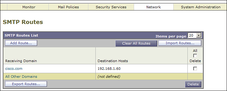
Figure 13-7. SMTPRoutes Page on a Standalone ESA
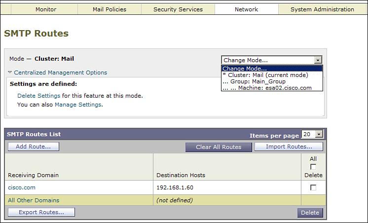
Figure 13-8. SMTPRoutes Page on a Clustered ESA
The extra WUI elements in Figure 13-8 are
• Mode indicator: Tells you which mode you are currently in. In Figure 13-8, we’re at cluster mode in the cluster called Mail.
• Mode selector box: The drop-down on the right indicates we’re currently at cluster mode and gives us an option to select group or machine mode. With multiple machines in the cluster, you can actually select machine mode for another ESA in the cluster.
• Centralized Management Options: When you expand the options window, you’re given links to manage the settings for this particular configuration page. You can delete, copy, or move the current settings to another cluster mode.
Whenever you reach a page for a setting that’s configured at a different cluster mode than your current setting, you receive a warning about the mode. You won’t be able to make any changes to the configuration unless you change modes or modify the CM settings for this page. Figure 13-9 shows the warning.
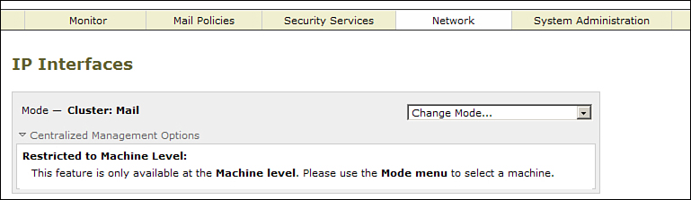
Figure 13-9. CM Mode Warning
Figure 13-10 shows a slightly different version of this warning, with a cluster mode configuration page shown to an administrator using the machine mode. In this case, the settings are shown on the screen, grayed out, because although the settings apply to this mode because they are inherited from the cluster, they cannot be edited at this mode.
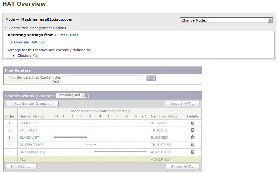
Figure 13-10. HAT Overview, a Cluster Setting, in Machine Mode
In general practice, you’ll probably be setting up your CM settings for configuration once, when you establish the cluster. From then on, any administrative work you’re doing will apply to one of the cluster modes. You’ll quickly get into the habit of using the drop-down box to select the right mode, and the WUI itself will clearly tell you your current mode and the mode that the page is configured in.
If you want to change how a particular table or setting is handled in the cluster, you can do that by clicking the Manage Settings link in the Centralized Management Options section of the configuration page you want to modify. Figure 13-11 shows this for DNS settings.
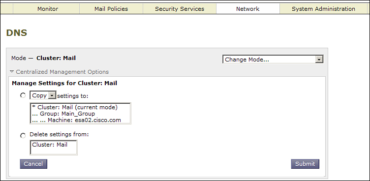
Figure 13-11. Managing CM Settings in the WUI
To establish new settings at another layer of the cluster, you have the choice of copying or moving the setting from somewhere else. There’s also a delete option, to remove settings at a particular mode. Deleting or moving will leave the page with no settings at that level, which is fine because the setting will be configured at another. In the earlier example using groups named SFO and PHL, it’s perfectly acceptable to delete the value at the Cluster mode, because all the machines derive their DNS server settings from the group they’re in. We could also have started the configuration by moving the DNS setting from cluster to group, rather than copying.
Using CM in the CLI
When using the CLI on a clustered machine, there are a few changes to the normal CLI interface. First, the command prompt changes to indicate the mode you’re currently operating in, whether Machine, Group, or Cluster:
(Cluster Mail)>
Further, every configuration command in the CLI has two new menu options: clusterset and clustershow. Here’s an example of dnsconfig in a cluster:
(Cluster Mail)> dnsconfig
Currently using the Internet root DNS servers.
No alternate authoritative servers configured.
Choose the operation you want to perform:
- NEW - Add a new server.
- SETUP - Configure general settings.
- CLUSTERSET - Set how DNS settings are configured in a cluster.
- CLUSTERSHOW - Display how DNS settings are configured in a cluster.
[]>
Clustershow is used to list where this command is configured: cluster, group, or machine mode. Some settings can be configured at more than one level, and the most specific match for this ESA “wins.” Clusterset allows you to change the level at which the command is configured, and copy or move the configuration setting to another level.
Whenever you’re in a cluster mode for which a given command is not yet configured, the CLI gives you this warning:
(Machine esa02.cisco.com)> smtproutes
NOTICE: This configuration command has not yet been configured for the current
cluster mode (Machine esa02.cisco.com).
What would you like to do?
1. Switch modes to edit at mode "Cluster Mail".
2. Start a new, empty configuration at the current mode (Machine esa02.cisco.
com).
3. Copy settings from another cluster mode to the current mode (Machine esa02.
cisco.com).
The CLI is prompting you to either move to the proper cluster mode or establish a new configuration at the current cluster mode. Most of the time, the first option is the right one, which is why it’s the default. Pressing Enter moves you to the right cluster mode.
Some commands, like monitoring, status, and log searching, are limited to machine level on the machine you’re currently logged into. No, you can’t search logs of other ESAs in the cluster from one SSH login. When you run a command that requires you to be in login machine mode, you are presented with this warning:
(Group PHL)> w
This command is restricted to run in machine mode of the machine you are logged
in to. Do you want to switch to "Machine esa02.cisco.com" mode? [Y]>
Again, the default is what you want, provided you really want to run the command that you typed. Commands that apply to the management and monitoring of clusters, like clusterconfig and clustercheck, are restricted to cluster mode. No commands are restricted to group mode.
The commands limited to machine mode are listed in Table 13-2. Most of these commands can be run on any machine in the cluster from a single login. In other words, you can log in to host A, change mode to machine on host B, and run a command like delivernow. That command will affect mail queued on host B.
Table 13-2. CLI Commands Restricted to Machine Mode
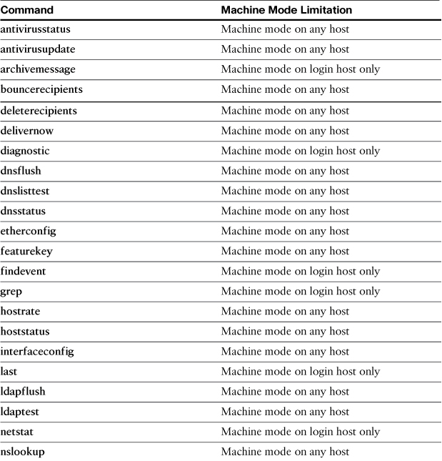
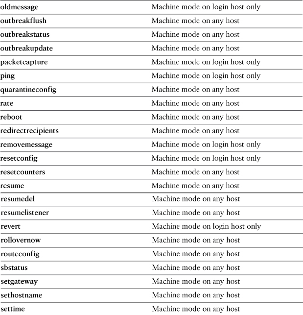
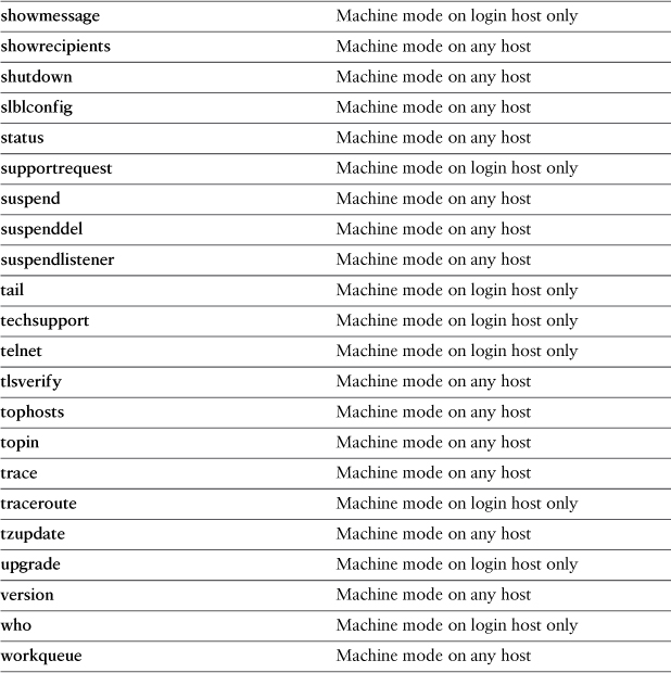
Table 13-2 also lists commands that are limited to machine mode on the host you’re logged into. If you run these commands in any other mode, or in machine mode for another host, you’ll be prompted to change to machine mode of the login host. For more detail on any of these commands, refer to Chapter 5.
All the other commands not listed in Table 13-2 are available at any CM mode.
Centralized Management Limitations and Recommendations
The ESA CM model is extremely flexible and makes synchronization of configuration a breeze. Frankly, I wouldn’t run multiple ESAs without it. However, it has some limitations, and there are some recommendations to mitigate those limitations.
An important recommendation is for you to not be afraid of adding and removing machines from a cluster. Nothing is lost, and the cluster settings, including all the group settings, are preserved, as long as one machine is still in the cluster. There are plenty of occasions that call for removing a machine temporarily to perform some work and reconnecting later. Even if an ESA is intended to run independently, it can be useful to connect it to a cluster to receive common configuration items like policy, filters, and administrative settings, and then disconnect it for its specific configuration.
Size of CM Clusters
The first limitation is the number of ESAs that can practically be included in a single cluster. Cisco designed the feature to support 20 ESAs in a single cluster, but due to the peer-to-peer nature, practical considerations should limit a single cluster to 15–18 systems. An environment this large is not typical: ESA deployments of more than 8 systems probably represent less than 5% of Cisco ESA customers. Most environments of this size, with multiple physical locations and ESAs configured in layers, are anyway likely to find more benefit in running multiple clusters based on location or function.
Configuration Files in Clusters
Configuration file management becomes more difficult in an ESA cluster mode. You can still export a configuration file in XML format, but this exported file cannot be used to restore the cluster or an individual machine. The good news here is that you usually don’t have to: Replacing a machine is as easy as putting it on the network and joining the cluster. The machine gets its settings from the other ESAs.
If you require the ability to backup and restore configurations of individual machines, you can remove a machine from the cluster, export, and then join the cluster again. This process isn’t harmful: The configuration is “flattened” for the individual machine and the resulting file can be used to restore the configuration.
Upgrading Clustered Machines
Upgrades present a special challenge with CM clusters, because all appliances in the cluster must be running exactly the same version and build. In fact, the upgrade process disconnects all machines from the cluster as the first step when you run the upgrade command on a clustered ESA. This can create some headaches when you’re not upgrading all the appliances in a cluster at once.
First, if you plan to upgrade a single machine, disconnect it from the cluster first to avoid the disconnection of all machines. After the upgrade and reboot, the ESA maintains the cluster identity, and you can even reconnect the machine. However, because it’s running a newer version of AsyncOS, you essentially have a new cluster at the new AsyncOS level.
Let’s illustrate this process with an example. Suppose you have four ESA hosts called A, B, C, and D, in a cluster called Mail. Each ESA is running 7.5.0, and you want to upgrade each to the 7.5.1 point release. Here are the steps to upgrade all four ESAs:
1. Remove the first ESA, machine A, from production by suspending the listeners and drain the queues as previously discussed . This step is optional, but highly recommended.
2. Connect to the CLI and run clusterconfig. Choose the DISCONNECT option in the menu and disconnect the ESA you’re currently logged into. Your CLI prompt now changes to (Cluster Mail) [Disconnected]>.
3. Run the upgrade command in the CLI or connect to the WUI and use the System Upgrade page on the System Administration menu. I prefer the WUI for upgrades. You can ignore the message that says You must disconnect all machines in the cluster in order to upgrade them. It’s not accurate in this case, if you’ve already disconnected the machine you’re logged into. Answer Y to the query Do you wish to disconnect all machines in the cluster now? The disconnect will not be sent to other machines provided you’ve already disconnected the machine you’re logged into.
4. Allow the upgrade to proceed and reboot at the end of the process. Confirm that the ESA has the new version installed. Connect to the CLI command and run clusterconfig. The CLI should ask you if you want to reconnect to the cluster. Answer Y to have the machine reconnected to the cluster. Once you’re satisfied, don’t forget to resume services if you suspended them in Step 1.
At this point, having upgraded only machine A, you now effectively have two clusters: one at version 7.5.1 with only machine A as a member, and one at 7.5.0 with machines B, C, and D. Cluster communications will not synchronize between the two versions. To complete the upgrade, repeat all four of the steps with machines B, C, and D.
You can certainly perform some of the machine upgrades simultaneously, if you have capacity to shift email traffic to the others. In the example, if two ESAs can handle the whole traffic load for your environment, you can upgrade A and B first and then when they are restarted and reconnected, repeat the process with C and D.
Summary
Almost every environment based on ESA will include more than one appliance, because of throughput or redundancy requirements. There a number of ways to scale your environment to meet those requirements, and you should be able to confidently choose a model that works for your organization. This chapter covered the topics of deploying groups of ESAs using MX records and load balancers, mixing ESA with other SMTP servers, and adding or replacing ESAs.
Once deployed, you need to manage all of your ESAs, and we covered the use of the CM service and protocol and discussed how it differs from administering a standalone ESA. We covered replacing and upgrading machines that are part of a CM cluster.
The next chapter combines everything we’ve learned so far about Internet email security and ESA and looks at the big picture of architectures and policies for maintaining a highly available and highly secure SMTP edge.