Chapter 8. Wireless Security
This chapter covers the following topics:
• Overview of Cisco Unified Wireless Network Architecture
• Authentication and Authorization of Wireless Users
• Lightweight Access Point Protocol (LWAPP)
• Wireless Intrusion Prevention System Integration
• Management Frame Protection (MFP)
• Network Admission Control (NAC) in Wireless Networks
Wireless networks are becoming more and more popular. Not only can you take advantage of wireless networking at the office, home, a hotel, and coffee shops, but also at airports, train stations, and many other places. Wireless networks increase productivity. Your employees can save time by sending and receiving e-mail or accessing information on network servers from a conference room or any location within your organization that has wireless connectivity. You can also implement a voice over wireless LAN (WLAN) solution. With a WLAN, your employees can reach each other anywhere within your organization without having to rely on cellular coverage that can be spotty or nonexistent.
Now the bad news: wireless networks are a major target for attackers. One of the biggest challenges today is to make sure that the appropriate tools and mechanisms are used to protect data in-transit across wireless networks. In addition, the wireless infrastructure needs to be protected against attacks targeted to the wireless networking devices. Stories abound of attackers gaining access to wireless networks not only to steal information but also to attack other networks.
After reading this chapter, you will become familiar with some of the technologies, tools, and mechanisms that are typically used to protect your wireless network. You will also learn best practices to use when securing the Cisco Unified Wireless Architecture.
The 802.11a, 802.11b, and 802.11g are the most widely deployed WLAN technologies today. Historically, 802.11 WLAN security includes the use of open or shared-key authentication and static wired equivalent privacy (WEP) keys. This combination offers a rudimentary level of access control and privacy but each element can be compromised.
The low cost of wireless deployments makes them popular (that is, you do not have to worry about expensive cabling solutions and portability issues). However, inexpensive equipment also makes it easier for attackers to gain unauthorized access. Rogue access points and unauthorized, poorly secured networks compound the odds of a security breach. The best practices you learned in previous chapters play a crucial role when protecting the infrastructure, analyzing risks, and building the most appropriate operational security program for your organization.
In this chapter, you will also learn the different authentication mechanisms in wireless networks. In addition, you will become familiar with advanced topics such as:
• Wireless intrusion detection and prevention services (IDS/IPS)
• Network Admission Control (NAC) in wireless networks
Overview of Cisco Unified Wireless Network Architecture
The Cisco Unified Wireless Architecture is a multiservice solution designed for any type of organization. It can be deployed in your corporate offices, branches, retail stores, hospitals, manufacturing plants, warehouses, educational institutions, financial institutions, government agencies, and any other type of organization that needs wireless connectivity. Industry standards including the IEEE 802.11 and the draft IETF Control and Provisioning of Wireless Access Points (CAPWAP) are supported.
Because the Cisco Unified Wireless Network is a multiservice solution, it supports data, voice, and video applications. Some examples of data applications are as follows:
• Internet access
• Virtual private network (VPN) access
• Inventory management applications
• Asset tracking
• Mobile healthcare applications
You can also run Voice over IP (VoIP) over WLAN. The Cisco Unified Wireless Network Architecture also supports video, such as video surveillance applications, video streaming applications for e-learning, and others. The Cisco Unified Wireless solution provides interoperability with the Cisco Wireless IP Phones to provide comprehensive voice communications using Cisco Unified CallManager and Cisco Wi-Fi access points. The Cisco Compatible Extensions program gives third-party manufacturers the ability to design industry-standard and Cisco innovations into a wide variety of devices. Other advanced features such as wireless intrusion detection and prevention, precise location tracking, and Network Admission Control (NAC) are also supported.
You can implement wireless networks in all sizes. For example, you can have merely a couple of wireless access points or wireless routers within your organization, as illustrated in Figure 8-1.
Figure 8-1. Basic Wireless Network
In Figure 8-1, a wireless access point and a wireless router are accepting connections from end-user workstations, laptops, and wireless scanners. This approach is only appropriate for small environments. It is not feasible for medium and large organizations because it does not provide centralized management and ease of deployment. The Cisco Unified Wireless Network solution provides centralized management that allows you to easily deploy WLAN configurations with the same level of security, scalability, and reliability to all wireless networking devices within your organization. Figure 8-2 illustrates the main components of the Cisco Unified Wireless Network.
Figure 8-2. The Cisco Unified Wireless Network Architecture
The following are the primary components of the Cisco Unified Wireless Network solution (as illustrated in Figure 8-2):
• WLAN management: Centralized management enables configuration of the same level of security, scalability, and reliability features throughout your organization. You can use the CiscoWorks Wireless LAN Solution Engine (WLSE) or the CiscoWorks WLSE express.
• Wireless LAN controllers: Provision of centralized intelligence for wireless access point management.
• Access points: Devices to which mobile devices connect.
• Mobile clients: End-user workstations, laptops, personal assistant (PDAs), and other wireless devices that ensure peak performance and interoperability.
• Mobility services: Services such as voice over wireless LAN, wireless intrusion detection and prevention, precise location tracking (Cisco WLAN Location Appliance), and others.
Note
For general information about the Cisco wireless devices, go to http://www.cisco.com/go/wireless.
You can deploy wireless access points within your organization in two modes: unified mode (as illustrated in Figure 8-2) and autonomous mode. In autonomous mode, a WLSE network management appliance is deployed with autonomous access points. Some access points act as domain controllers (WDS) for sets of access points communicating over the wired network using the Wireless LAN Context Control Protocol (WLCCP). This is illustrated in Figure 8-3.
Figure 8-3. Autonomous Wireless Access Points
The main difference between the unified and autonomous modes is that in unified mode, access points operate with the Lightweight Access Point Protocol (LWAPP) and work in conjunction with Cisco wireless LAN controllers and the Cisco Wireless Control System (WCS). When configured with LWAPP, the access points can automatically detect the best-available Cisco wireless LAN controller and download appropriate policies and configuration information with no manual intervention. Autonomous access points are based on Cisco IOS software and may optionally operate with the Cisco WLSE. Autonomous access points, along with the Cisco WLSE, deliver a core set of features and may be field-upgraded to take advantage of the full benefits of the Cisco Unified Wireless Network as requirements evolve.
You can individually manage Cisco Aironet autonomous access points via the command-line interface (CLI), a web interface, the CiscoWorks WLSE, or CiscoWorks WLSE Express. On the other hand, Cisco recommends that you upgrade any existing Cisco Aironet access points operating autonomously to run LWAPP and operate them as lightweight access points to receive all the features, benefits, and mobility services of the Cisco Unified Wireless Network.
Note
Cisco provides free upgrade software for existing customers at http://tools.cisco.com/support/downloads/pub/MDFTree.x?butype=wireless.
Authentication and Authorization of Wireless Users
The 802.11 standard supports different types of authentication. The two most generic types are open and shared-key authentication. In most wireless networks, a service set ID (SSID) is specified to identify the wireless network. The basic mechanisms of 802.11 augment the identification by using SSIDs with authentication mechanisms that prevent the client from sending data to and receiving data from the access point unless the client has the correct shared key. One of the most basic wireless authentication protocols is the wired equivalent privacy (WEP) standard. The following section describes WEP in detail.
WEP
WEP, an optional encryption standard in 802.11 that most vendors support, is implemented in the MAC layer. WEP-enabled devices encrypt the payload of each 802.11 frame before transmission by using an RC4 stream cipher. The packets are then decrypted in the wireless access point. WEP encrypts only data between 802.11 stations. After the frame enters the wired side of the network, WEP no longer applies.
During the encryption process, WEP arranges a key schedule (otherwise known as a seed) by concatenating the shared secret key supplied by the user of the sending station with a random-generated 24-bit initialization vector (IV). The IV lengthens the life of the secret key because the station can change the IV for each frame transmission. WEP inputs the resulting seed into a pseudorandom number generator that produces a key-stream equal to the length of the frame payload plus a 32-bit integrity check value (ICV), as illustrated in Figure 8-4.
Figure 8-4. WEP Process

The following steps are illustrated in Figure 8-4:
1. The ICV is calculated using CRC-32 and concatenated to the plaintext message.
2. A random IV and the shared secret key are also concatenated producing the seed.
3. This seed is the input to the WEP Pseudorandom Number Generator (PRNG). WEP uses RC4 PRNG of RSA Data Security to produce a pseudorandom sequence.
4. The message is encrypted by using an XOR operation with the sequence generated in the previous step.
5. The encrypted message is sent to the other end.
The ICV is a check sum that the receiving station eventually recalculates and compares to the one sent by the sending station to determine whether the transmitted data underwent any form of tampering while in transient. If the receiving station calculates an ICV that does not match the one found in the frame, the receiving station can reject the frame or flag the user.
Note
WEP shared secrets use 40-bit, 64-bit, or 128-bit keys.
WEP has some limitations and has undergone extensive examination and criticism over the past years. In short, WEP is vulnerable because of its relatively short IVs and keys that remain static. For a large, busy network, this reoccurrence of IVs can happen within an hour or so. Because of this, you will have many frames or packets with similar key-streams. Technically, an attacker can gather frames based on the same IV to determine the shared values among the wireless devices. This information can be key-stream or the shared secret key. The static nature of the shared secret keys emphasizes this problem. In many cases, system administrators and users use the same keys for months or even years. This gives mischievous culprits plenty of time to monitor and attack the WEP-enabled networks. Now some vendors deploy dynamic key distribution solutions based on 802.1X, which definitely improves the security of wireless LANs.
Many now recommend the use of IP security (IPsec) to ensure data confidentiality, integrity, and authenticity. The only caveat is that when you deploy IPsec in a WLAN environment, you need to install an IPsec software client on every machine that connects to the wireless network.
WEP has several enhancements. The first one is the use of the Temporal Key Integrity Protocol (TKIP).
Note
TKIP is often referred to as WEP Version 2.
The second enhancement is the use of the Advanced Encryption Standard (AES) encryption protocol instead of RC4, which is used in older WEP implementations.
The Wi-Fi Protected Access (WPA) standard uses TKIP to provide additional security features. WPA is discussed in the next section.
WPA
WPA (using TKIP) includes a per-packet keying (PPK) and message integrity check (MIC) and an extension of the initialization vector from 24 bits to 48 bits. WPA mitigates the WEP threat by implementing different keys on a per-packet basis. It does this by hashing the IV and WEP keys to produce a temporal key. This temporal key is then combined with the IV and fed to an XOR operation with the plaintext message.
Today WPA combines TKIP and user authentication via IEEE 802.1x and the EAP (Extensible Authentication Protocol). This combination mitigates vulnerabilities from several angles and represents a significant security upgrade over WEP.
Note
The following site includes a whitepaper with detailed information about WEP, WPA, and other authentication mechanisms:
802.1x on Wireless Networks
In Chapter 1, "Technology Overview," you learned the basics of the 802.1X. As a refresher, 802.1x is a standard that defines the encapsulation methodologies for the transport of the Extensible Authentication Protocol (EAP) protocol.
Note
EAP was originally defined in RFC 2284, which is now obsolete due to RFC 3748.
The 802.1X standard allows you to enforce access control when wired and wireless devices attempt to access the network. Figure 8-5 illustrates the main components of 802.1x.
Figure 8-5. 802.1x in Wireless Networks
The following are the main components of 802.1x illustrated in Figure 8-5:
• Supplicant: Software running on the client workstation
• Authenticator: The wireless access point
• Authentication Server: RADIUS server such as the Cisco Secure Access Control Server (ACS)
• External Database: External database such as the Microsoft Active Directory, Lightweight Directory Access Protocol (LDAP), or any Open Database Connectivity (ODBC) repository.
Note
The Cisco comprehensive identity-based solution, which is based on 802.1x, is referred to as Identity Based Networking Services (IBNS).
The basic 802.1x authentication negotiation scheme is illustrated in Figure 8-6.
Figure 8-6. 802.1x Authentication Negotiation Basics

The following are the steps illustrated in Figure 8-6:
1. The client attempts to connect to the wireless network, and the wireless access point sends an EAP identity request to the client (supplicant).
2. The user enters his credentials, and the client machine sends the EAP identity reply to the wireless access point.
3. Depending on the EAP method, the client starts an authentication exchange to the authentication server. An EAP tunnel passes directly to the authentication server.
4. The authentication server accepts or rejects the user and sends further information/instructions based on the authentication and authorization of the user.
At the end of the session, the client sends an EAPOL Logout message.
The different types of EAP methods are categorized as follows:
• Challenge/response based
• Cryptographic based
• Tunneling methods
• Generic token and one-time-passwords
The challenge-response-based EAP methods are the following:
• EAP with Message Digest 5: Uses MD5 hashing for authentication exchange
• Cisco LEAP: Authentication based on usernames and passwords
• EAP using the Microsoft Challenge Handshake Authentication Protocol Version 2 (MSCHAPv2)
The cryptographic-based EAP method is as follows:
• EAP over Transport Layer Security (EAP-TLS): Uses x.509 digital certificates and TLS for authentication
The most common EAP tunneling methods are as follows:
• Protected EAP (PEAP)
• EAP Tunneling Transport Layer Security (EAP-TTLS)
• EAP Flexible Authentication via Secure Tunneling (EAP-FAST): Designed not to require certificates
The EAP Generic Token Card (EAP-GTC) is an EAP method used for generic token cards and one-time passwords.
Note
EAP-GTC is defined in RFC 3748. It does not protect the authentication data in any way.
The following sections describe each EAP method.
EAP with MD5
When you configure EAP-MD5, both the client and the authentication server must have a shared secret established out-of-band. This shared secret is typically a password associated with an identity/username. Figure 8-7 illustrates the primary steps within the EAP-MD5 authentication method.
Figure 8-7. EAP-MD5

The following are the steps illustrated in Figure 8-7:
Step 1. A random challenge is sent to the supplicant from the wireless access point.
Step 2. The client sends its response containing the hash of the challenge created using the shared secret.
Step 3. The RADIUS authentication server verifies the hash and accepts or rejects the authentication.
Step 4. The wireless access point allows or disallows access based on the RADIUS authentication server decision.
Step 5. If the authentication is successful, the client gains access to the network.
Because EAP-MD5 is purely an authentication protocol, it does not provide encryption after the authentication process. Therefore, all the messages are transmitted in cleartext after authentication. In addition, because it is only a client authentication protocol, the server side is not authenticated. Subsequently, you cannot detect rogue wireless access points if you implement EAP-MD5. The use of mutual authentication provides a means of reducing the risk of users installing rogue access points within the infrastructure, because mutual authentication also requires the client to authenticate the server and, most definitely, rogue devices will not do this. Another way you can try to protect against rogue access points is to lock down your switches so that you can use only authorized MAC addresses on your wired network. This is explained later in this chapter.
Tip
EAP-MD5 is vulnerable to dictionary and brute-force attacks when used with Ethernet and wireless.
Cisco LEAP
Cisco LEAP was initially developed to address the vulnerabilities that WEP showed. At that time, it was an alternative protocol that allowed you to deploy wireless networks without requiring a certificate infrastructure for clients by leveraging authentication mechanisms that were already available within the infrastructure. The following are some of the benefits presented by using Cisco LEAP:
• 802.1x EAPOL messages are used within Cisco LEAP.
• Server authentication is achievable.
• The client username and password are sent over MS-CHAP.
• RADIUS is used as the authentication server.
• LEAP provides mechanisms for deriving and distributing encryption keys.
Many people are now migrating from Cisco LEAP to full 802.1x implementations.
EAP-TLS
EAP-TLS provides several features. For example, it supports mutual authentication providing an encrypted transport layer and the capability to change the keys dynamically. EAP-TLS requires the use of digital certificates. You need to keep this in mind when thinking about deploying EAP-TLS within your network.
Note
EAP-TLS is defined in RFC 2246.
During the TLS handshake phase, the client and wireless device establish a session exchanging symmetric session keys used to encrypt the transport during the data transfer phase. TLS has two layers:
• Record layer: Includes information about fragmentation, MAC, and encryption
• Message layer: Includes four different types of messages
The following are the four message types:
• Change cipher spec: This defines a change in the session context to be used by the record layer.
• Alert message: There are approximately 26 different alert message subtypes. (They include access denied, close notify, decryption failed, and certificate revoked.)
• Handshake protocol: During the handshake protocol, the client and the server exchange different hello messages; server authentication and key exchange messages; client authentication and key exchange messages; and the finalization message to close the session.
• Application data: This is the actual data that is transmitted over the TLS tunnel.
EAP-TLS does not use all parts of the TLS record protocol; however, it uses the TLS handshake for mutual authentication, for cipher suite negotiation, and for derivation of the session keys. EAP-TLS was initially designed for PPP connections; however, in wireless implementations, EAP-TLS is used as a strong and secure mechanism for mutual authentication and key establishment; then the native WEP mechanisms of the wireless device are used to encrypt the data.
PEAP
Many people refer to PEAP as the true EAP-TLS in wireless implementations. PEAP uses EAP-TLS functionality by securing the open exchanges, but it keeps things simple. For instance, PEAP requires only server-side certificates; however, it can still perform mutual authentication between the client and the server. It also uses TLS for the secure tunnel and lengthens the EAP-TLS exchange beyond the finished message to add client authentication and key exchange. One of the disadvantages of PEAP is that it is considered to be a chatty protocol. The PEAP protocol has two phases:
• Phase 1: Used to establish a secure tunnel using the EAP-TLS with server authentication
• Phase 2: Authenticates the client based on EAP methods, exchange of arbitrary information, and other PEAP-specific means using the information established during Phase 1
Many people use PEAP because it is simple to implement within a wireless infrastructure.
EAP Tunneled TLS Authentication Protocol (EAP-TTLS)
EAP-TTLS is basically the same as EAP-TLS; however, it extends the client authentication by the use of a method called tunneled authentication. With EAP-TTLS, the client does not need a digital certificate (only the authentication server requires one), thereby simplifying the client identity management.
Note
EAP-TTLS enables you to also use legacy authentication methods such as password-based methodologies.
EAP-FAST
EAP-FAST was initially known as the Tunneled EAP (TEAP) and as LEAP Version 2. EAP-FAST is classified by many as the most comprehensive and secure EAP type suitable for wireless implementations. It addresses the risks of man-in-the-middle and dictionary attacks. In addition, EAP-FAST reduces the hardware requirements, making it a flexible deployment model and more attractive to many people.
EAP-FAST authentication does not require the use of a specific encryption type. Instead, the WLAN encryption type to be used is determined by the client wireless network interface card capabilities.
If the client devices do not support WPA2 or WPA, you can deploy 802.1X authentication with dynamic WEP keys, but, because of the well-known exploits against WEP keys, this WLAN encryption mechanism is not recommended. If you must support WEP-only clients, it is recommended that you employ a session-timeout interval which requires that the clients derive a new WEP key on a frequent interval.
Tip
30 minutes is the recommended session interval for typical WLAN data rates.
Cisco has a comprehensive list of frequently asked questions about EAP-FAST at http://www.cisco.com/en/US/products/hw/wireless/ps4555/products_qanda_item09186a00802030dc.shtml.
EAP-GTC
EAP-GTC enables you to use hardware token cards as one-time-passwords. An example of a hardware token card is the RSA SecurID solution.
Note
For more information about RSA SecurID, go to http://rsa.com.
You can use EAP-GTC inside the TLS tunnel created by PEAP. You can use this EAP method to implement a two-factor authentication solution to avoid common password compromises and combine it with your remote access VPN solution. For instance, a user can use the token card for both wireless and remote access VPN authentication. If you are just starting to deploy a WLAN, you must decide whether token deployment is cost effective. Many people justify the cost of token deployment by using this authentication mechanism with other network infrastructure authentication, such as remote access VPN.
In summary, the two EAP methods that most people implement today are EAP-FAST and PEAP. EAP-FAST provides more flexibility when deployed with 802.1x or NAC. EAP-FAST is easy to implement, and it is not Cisco proprietary. It supports Windows single-sign-on and provides support for login script operation with any user database such as Microsoft Active Directory, Lightweight Directory Access Protocol (LDAP), and one-time password (OTP). In addition, because EAP-FAST does not require certificates, you can configure it easily and distribute it for Cisco Aironet client devices with the Cisco Aironet Configuration Administration tool.
Tip
It is recommended that you employ either WPA2 (AES-CCM) or WPA (TKIP) encryption, which are both dependent on the NIC card capabilities in the specific deployment.
Configuring 802.1x with EAP-FAST in the Cisco Unified Wireless Solution
This section describes how to configure the wireless LAN context (WLC), the Cisco Secure Services Client (CSSC), and Cisco Secure Access Control Server (ACS) to perform 802.1x authentication using EAP-FAST. Figure 8-8 illustrates the topology used in this configuration example.
Figure 8-8. Configuring 802.1x with EAP-FAST on the Cisco Unified Wireless Solution

Figure 8-8 shows a workstation with the CSSC connecting to a Cisco wireless access point (with IP address 172.18.85.123) in a lightweight configuration controlled by a WLC. The management IP address of the WLC is 172.18.85.96, and the AP manager IP address is 172.18.85.97. The WLC forwards all authentication requests to a Cisco Secure ACS.
Configuring the WLC
Complete the following steps to configure the WLC to use the Cisco Secure ACS server for authentication. Cisco Secure ACS validates the user credentials using the Windows database. (The Cisco Secure ACS server configuration is covered in the next section.)
Step 1. Log in to the WLC as an administrator and click the Security tab; then click New to add a new RADIUS server, as illustrated in Figure 8-9. You will then see the screen shown in Figure 8-10.
Figure 8-9. Adding a RADIUS Server to the WLC
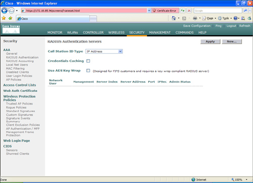
Figure 8-10. RADIUS Server Configuration on the WLC
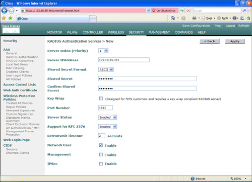
Step 2. In the screen shown in Figure 8-10, enter the RADIUS server information. In this case, the Cisco Secure ACS IP address is 172.18.85.181. Enter a shared key to mutually authenticate the WLC and the RADIUS server. In this example, the default RADIUS port UDP/1812 is used. Ports UDP/1645 (legacy) and UDP/1812 are supported by Cisco Secure ACS for RADIUS authentication. Leave all other options with the default values and click Apply.
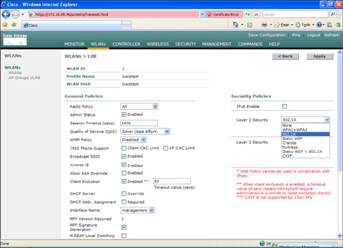
Step 3. By default, the WLC uses 802.1x for the security policies in WLANs. You can also combine 802.1x with static WEP, WPA, and others. In this example, 802.1x is used without WEP/WPA. To enable this configuration, navigate to the WLANs tab and edit the configured WLAN. (In this example, the WLAN SSID is named ciscotest.) Under Security Policies and Layer 2 Security, select 802.1x from the drop-down menu, as shown in Figure 8-11.
Figure 8-11. WLAN Layer 2 Security Policy
Step 4. Scroll down on the same screen and choose the configured Cisco Secure ACS server on the drop-down menu under the RADIUS Servers section, as shown in Figure 8-12. Click Apply.
Figure 8-12. Selecting the Configured RADIUS Server

The next section shows you how to configure the Cisco Secure ACS server.
Configuring the Cisco Secure ACS Server for 802.1x and EAP-FAST
Complete the following steps to configure the Cisco Secure ACS server for 802.1x authentication using the EAP-FAST method. You first add the WLC as AAA client on the Cisco Secure ACS server.
To add the WLC as a AAA client on Cisco Secure ACS, click the Network Configuration radio button. You can create a network device group to maintain a collection of AAA clients and AAA servers, or you can use the default Not Assigned network device group. In this example, the WLC is added to the Not Assigned default group. Click the Not Assigned group.
Step 1. Click Add Entry. The screen shown in Figure 8-13 is displayed.
Figure 8-13. Adding an AAA Client into Cisco Secure ACS

Step 2. Complete the form by entering the hostname and IP address of the WLC. (WLC is the hostname, and 172.18.85.96 is the management IP address of the WLC in this example.)
Step 3. Enter the shared secret to be used between the Cisco Secure ACS server and the WLC. (In this example, the key is 1qaz@WSX.)
Step 4. Choose RADIUS (Cisco Airspace) under the drop-down menu in the Authenticate Using section.
Step 5. Click Submit + Apply.
Step 6. In this example, the Cisco Secure ACS server queries an external Windows 2003 server for authentication credentials. Navigate through the radio button sequence as follows. Click External User Databases > Database Configuration > Windows Database > Configure.
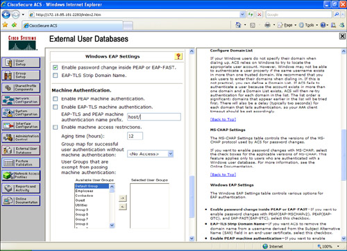
Step 7. Under the Windows EAP Settings, check the Enable password change inside PEAP or EAP-FAST checkbox, as illustrated in Figure 8-14.
Figure 8-14. Windows EAP Settings
Step 8. Click Submit.
Step 9. Navigate to External User Databases > Unknown User Policy and click the Check the following external user databases radio button.
Step 10. Click the Windows Database from External Databases to Selected Databases, as shown in Figure 8-15.
Figure 8-15. Selecting the Windows Database on the Unknown User Policy

Step 11. Click Submit.
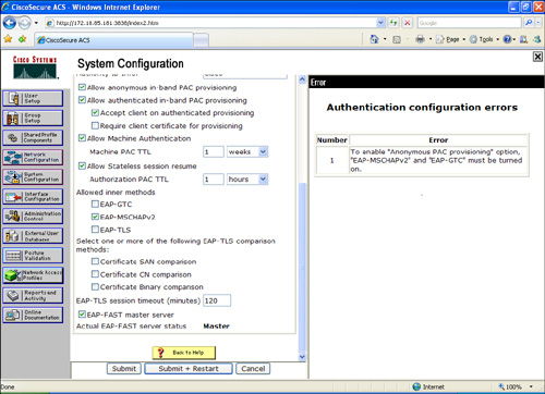
Step 12. Next, you have to enable EAP-FAST support on the Cisco Secure ACS Server. To do this, navigate via the radio buttons to System Configuration > Global Authentication Setup > EAP-FAST Configuration. The screen in Figure 8-16 is displayed.
Figure 8-16. Enabling EAP-FAST on Cisco Secure ACS

Step 13. Check Allow EAP-FAST.
Step 14. In this example, the recommended (default) values for Active master key TTL (1 month), Retired master key TTL (3 months), and Tunnel PAC TTL (1 week) are selected.
Step 15. The Authority ID Info text is shown on some EAP-FAST client software; in this case, cisco is the text configured and displayed. This can be anything you want. On the other hand, the CSSC (used in this scenario) does not display this descriptive text for the PAC authority. However, the word cisco will be displayed if any other client (802.1x supplicant) is used.
Step 16. Check the Allow anonymous in-band PAC provisioning checkbox. This enables Automatic PAC Provisioning for EAP-FAST-enabled clients.
Step 17. The CSSC supports EAP-FAST Version 1a, which uses MS-CHAPv2 for authentication. Scroll down and check EAP-MSCHAPv2 under the Allowed inner methods section, as shown in Figure 8-17.
Figure 8-17. EAP-MSCHAPv2 and EAP-FAST Master Server Configuration
Step 18. Check the EAP-FAST master server check box to configure this Cisco Secure ACS server as the master. The Actual EAP-FAST Master server status line will say Master. Any other Cisco Secure ACS servers (if present in your organization) will use this server as the master PAC authority to avoid the need to provision unique keys for each Cisco Secure ACS in a network.
Step 19. Click Submit + Restart.
Configuring the CSSC
This section shows how to configure the CSSC to authenticate to the wireless network using EAP-FAST. Complete the following steps to configure the CSSC.
Step 1. Launch the CSSC and click Create Network.
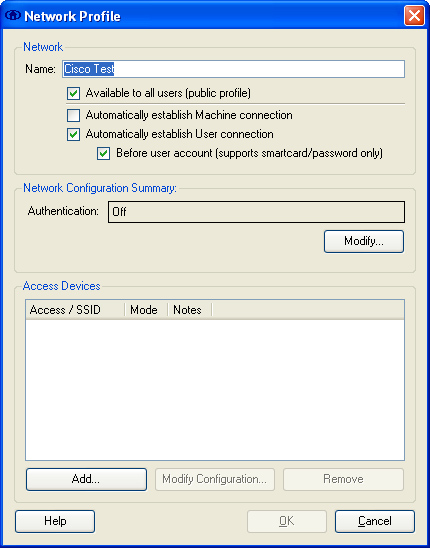
Step 2. The Network Profile screen shown in Figure 8-18 is displayed. Under Network Configuration Summary and Authentication, click Modify.
Figure 8-18. CSSC Network Profile Screen
Step 3. The Network Authentication screen shown in Figure 8-19 is displayed. Turn on authentication by clicking the radio button labeled Turn On under the Authentication Methods section, as illustrated in Figure 8-19. In this example, the Use Username as Identity button is selected, because the user credentials are being used for authentication.
Figure 8-19. CSSC Network Authentication Screen

Step 4. Under the Protocol list, check FAST and click the Configure button.
Step 5. The Configure EAP Method screen shown in Figure 8-20 is displayed. Under the Tunneled Method, you can choose Any Method to allow the CSSC to use any EAP method offered by the wireless infrastructure. In this example, the EAP-MSCHAPv2 method is selected, because we are doing external authentication to a Windows Active Directory user database. If, however, you choose the Any Method option, it will work, but in some cases, you may want to be selective to force the use of only one EAP method. (In this case, the method is EAP-MSCHAPv2.)
Figure 8-20. CSSC Configure EAP Method Screen

Step 6. Leave all other default values as they are, and click OK.
Step 7. Click OK in the Network Authentication screen.
Step 8. Only wireless networks that have SSIDs enabled for broadcast are visible within the CSSC. In this example, the WLC is configured not to broadcast the SSID. Consequently, you must manually define the SSID in the CSSC. To define the SSID in CSSC, click the Add button under the Access Devices section of the Network Profile screen. The SSID used previously is ciscotest.
Step 9. Click Add Access.
Step 10. Click OK.
Step 11. The CSSC attempts to connect to your wireless network. If it does not automatically make this attempt, click Connect from the CSSC main screen.
Step 12. You are prompted for your user credentials, and if successfully authenticated, you are granted access to the network.
Lightweight Access Point Protocol (LWAPP)
In the Cisco Unified Wireless Architecture, a wireless LAN controller (WLC) is used to manage the wireless access point configuration and firmware creating an LWAPP tunnel. LWAP provides the control messaging protocol and data encapsulation. In other words, the wireless client data packets are encapsulated between the access point and the WLC. Figure 8-21 illustrates how a WLC controls a wireless access point over an LWAPP tunnel.
Figure 8-21. LWAPP Tunnel
The following steps are illustrated in Figure 8-21:
1. The wireless client sends a packet to the wireless access point.
2. The wireless access point decrypts the packet and encapsulates it with an LWAPP header, forwarding it to the WLC.
3. The WLC removes the LWAPP header and forwards the packet to its destination in the corporate wired network.
Note
When a client on the corporate wired network sends replies to the wireless client, the packet first goes into the WLC where it is encapsulated with an LWAPP header and forwarded to the appropriate wireless access point. Subsequently, the access point removes the LWAPP header and encrypts the packet if necessary.
The LWAPP control messages are encrypted using the AES-CCM encryption method. The shared encryption key is derived and exchanged when the access point joins the WLC.
Note
The payload of the encapsulated LWAPP data is not encrypted. Therefore, you should follow infrastructure protection best practices to protect the wired network.
The following are the major steps or stages used in the LWAPP:
Step 1. Discovery: The wireless access point looks for a controller. The LWAPP Discovery Response from the controller contains the following important information from the WLC:
–Controller name (sysName)
–Controller type
–Controller capacity
–Current wireless access point load in the WLC
–Master controller status information used for redundancy
–Access point manager IP address and the number of access points joined to the manager
(a) When the AP is powered on, if a static IP address has not been previously configured, the AP issues a DHCP DISCOVER to get an IP address.
(b) If Layer 2 mode is supported, the AP attempts a Layer 2 LWAPP Discovery by sending an Ethernet broadcast message.
(c) If Layer 2 mode is not supported or the AP fails to find a WLC, the AP attempts a Layer 3 LWAPP Discovery.
(d) If a Layer 3 LWAPP Discovery also fails, the AP reboots and retries the first step.
Step 2. Join: The wireless access point attempts to establish a secured relationship with a controller.
Step 3. Image Data: The wireless access point downloads code from the WLC when needed.
Step 4. Config: The wireless access point receives the configuration from the WLC.
Step 5. Run: The wireless access point and the WLC are operating normally, and service data is exchanged.
Step 6. Reset: The wireless access point clears the current state, and this process starts over again.
The WLC provides support for radio resource management (RRM). The following are some of the advantages of RRM:
• Continuous analysis of RF environment
• Dynamic channel and power management
• Coverage hole detection and correction
• Coverage resiliency
The WLCs elect a radio frequency (RF) group leader who analyzes RF data and neighbor relationships to make more optimized decisions about the RF environment for wireless infrastructure. Multiple RF domains can coexist within a single RF Group. These RF domains can be intercontroller or intracontroller, as illustrated in Figure 8-22.
Figure 8-22. Multiple RF Domains
Why is this important to security? A good wireless network design that includes network resiliency is important for the overall security of your wireless network. The WLC has a built-in understanding of the signal strength that exists between lightweight access points within the same network. These controllers can use this information to create a dynamic optimal RF topology for the network. When a Cisco LWAPP-enabled access point boots up, it immediately looks for a wireless LAN controller within the network. After it finds a wireless LAN controller, the LWAPP-enabled access point sends out encrypted "neighbor" messages. These neighbor messages include the MAC address and signal strength of any neighboring access points. In a single wireless LAN controller network, the controller uses this neighbor information to determine the relative spatiality of the access points in the network. The controller then tunes each access point channel and optimal signal strength for optimal coverage and capacity.
When wireless LAN controllers are clustered in the network, a default controller is chosen. All the controllers feed the default controller information to their registered access points. The default controller correlates information for all the access points in the network and then pushes out the optimal channel and power for every access point on the network. The algorithms built into the Cisco Unified Wireless Network architecture prevent the interruption of wireless connectivity.
Wireless Intrusion Prevention System Integration
You can integrate Cisco IPS sensors with the Cisco Unified Wireless Solution. This includes the Cisco IPS sensors, the Cisco Adaptive Security Appliance (ASA), Advanced Inspection and Prevention Security Services Module (AIP-SSM), the Catalyst 6500 Intrusion Detection/Prevention Services Module Version 2 (IDSM-2), and the IPS modules for Cisco IOS routers. When you integrate IPS with the Cisco Unified Wireless Solution, the WLC talks to the Cisco IPS sensor via its management port using the Security Device Event Exchange (SDEE) protocol over TCP port 443. The WLC supports up to five IPS sensors.
Note
The WLC also supports the use of a certain limited number of IPS signatures that you can enable to detect security threats within your wireless network. However, the combination of an external IPS device with the WLC provides more granular inspection and detection.
The WLC Software Release Version 4.x and later supports shunning (blocking) from the IPS sensors. A shun request needs to be sent to the WLC from the Cisco IPS device to trigger the client blacklisting or exclusion behavior available on the controller. The WLC queries the Cisco IPS device at a configured query rate to retrieve all the shun events. This is illustrated in Figure 8-23.
Figure 8-23. IPS Sensor Integration

The following steps are illustrated in Figure 8-23:
Step 1. An infected client sends malicious traffic over the wireless network (through access point 1 (AP1)).
Step 2. The WLC sends the traffic to be inspected by the IPS device (IPS Sensor1).
Step 3. The IPS device sends a shun request to the WLC to block the offending client.
Step 4. The client is blocked (shunned).
Note
The shunned client status is maintained on each controller in the mobility group even if any or all of the controllers are reset. On the controller, clients are disabled based on a MAC address, even though the shun request that the IPS initiates uses the client IP address as its destination. Therefore, although a client remains disabled for the duration of the controller exclusion time and is re-excluded if it reacquires its previous DHCP address, that client is no longer disabled if the IP address of the client that is shunned changes Here is an example. The client connects to the same network, and the DHCP lease timeout has not expired.
Configuring IDS/IPS Sensors in the WLC
You can configure IDS/IPS using the WLC web management console or through the CLI. This section demonstrates how to use the web management console to add IDS/IPS sensors.
Step 1. Connect the Cisco IPS device to the same switch where the WLC resides.
Step 2. Mirror the WLC ports that carry the wireless client traffic to the Cisco IPS device. You do this because the Cisco IPS device must receive a copy of every packet to be inspected on the wireless network. The Cisco IPS device provides a downloadable signature file that you can customize. When a signature is triggered, the Cisco IPS device generates the alarm with a shunning event action. The WLC polls the Cisco IPS device for alarms. When an alarm is detected with the IP address of a wireless client, which is associated to the WLC, the IPS device puts the client into the exclusion list. The WLC generates a trap and notifies the WCS. The WLC removes the user from the exclusion list after the specified period (60 seconds by default).
Step 3. Log in to the WLC as an administrator.
Step 4. To add the Cisco IPS device to the WLC, navigate to the Security tab. Under CIDS, click Sensors.
Step 5. Click New.
Step 6. The screen shown in Figure 8-24 is displayed. Enter the sensor IP address. The IP address of the IPS device in this example is 172.18.85.149. The WLC uses SDEE, and the default port is 443. Enter the username and password of the Cisco IPS device.
Figure 8-24. Adding IPS Sensors

In this example, the query interval is configured for 15 seconds. This query interval is safe to use in most environments. Enter the Cisco IPS device SHA1 fingerprint. You can obtain this by invoking the show tls fingerprint command on the Cisco IPS device, as follows:
Example 8-1 IPS-sensor# show tls fingerprint
MD5: B8:A7:74:B5:62:AB:C8:15:5C:FE:E6:4C:0C:42:39:CE
SHA1: AC:6A:FA:FC:BE:05:D1:09:31:53:21:DC:36:A0:1A:B6:6A:DA:00:AF
The highlighted line shows the fingerprint that is entered into the WLC configuration. You must omit the colons (:) within the hexadecimal fingerprint. The fingerprint must be 40 characters in length.
Step 1. Click Apply.
Step 1. Navigate to WLANs and click Edit on the configured WLANs that you want to monitor. Make sure that Client Exclusion is enabled. The default client exclusion timeout is 60 seconds. On the other hand, the client exclusion persists as long as the IPS shun (block) remains active. The default block time in the Cisco IPS devices is 30 minutes.
Uploading and Configuring IDS/IPS Signatures
Several signatures come with the WLC by default. You can view the standard signatures by navigating to Security > Wireless Protection Policies and then clicking Standard Signatures. This is illustrated in Figure 8-25.
Figure 8-25. WLC Standard Signatures

You can also upload a signature file from the WLC to customize the signatures. To do this, navigate to Commands > Upload File > Signature File. To download the modified signature file, navigate to Commands > Download File > Signature File. After you download (or push) the edited signature file to the WLC, all registered wireless access points are refreshed in real time with the new signature configuration.
When customizing signatures, you must use the following format:
Name = <str>, Ver = <int>, Preced = <int>, FrmType = <frmType-type>, Pattern = <pattern-format>,
Freq = <int>, Interval = <int>, Quiet = <int>, Action = <action-val>, Desc = <str>
Note
The maximum length of each line is 1000 characters. The WLC will not correctly parse any lines longer than 1000 characters.
You can view the custom signatures by navigating to Security > Wireless Protection Policies and then clicking Custom Signatures.
Management Frame Protection (MFP)
Management Frame Protection (MFP) enables authentication of all 802.11 management frames between the WLC and wireless access points. MFP protects against direct and man-in-the-middle attacks. It also detects and reports potential phishing attacks. MFP has three main functions:
• Frame protection: This enables the wireless access point to protect the management frames by adding a message integrity check information element (MIC-IE) to each frame.
• Frame validation: The wireless access point validates every management frame that it receives from other access points in the network.
• Event reporting: The wireless access point notifies the WLC when it detects an anomaly. The WLC can also report these events via SNMP traps to management servers.
You can enable MFP globally. However, you can disable it on individual WLANs and access points. In other words, you can selectively enable or disable MFP on specific wireless access points or WLANs.
To enable MFP globally, navigate to Security > Wireless Protection Policies. Then click AP Authentication/MFP and choose Management Frame Protection from the Protection Type pull-down menu. You can view the MFP statistics under Security > Wireless Protection Policies > Management Frame Protection.
Precise Location Tracking
The Cisco Wireless Location Appliance uses RF fingerprinting technology to track mobile devices to within a few meters. This allows you to gain visibility into the location of people and assets. In addition, RF fingerprinting technology enables you to respond to security issues and thereby gain insight into the location and movement of people and assets, as well as locating rogue wireless access points.
The Cisco Wireless Location Appliance supports two location tracking options:
• On-demand location tracking: The user queries the location of the person or wireless device.
• Simultaneous location tracking: This automatically tracks up to thousands of 802.11 wireless devices by adding a Cisco Wireless Location Appliance in conjunction with a Cisco WCS.
Tip
It is recommended that you become familiar with the different methodologies used for location tracking and that you deploy these solutions within your network. Conventionally, many have used three different methods for locating wireless users or devices: closest access point, triangulation, and RF fingerprinting. As previously mentioned, the Cisco Wireless Location Appliance uses RF fingerprinting. A whitepaper explaining each methodology is located at http://www.cisco.com/en/US/products/ps6386/products_white_paper0900aecd80477957.shtml.
Network Admission Control (NAC) in Wireless Networks
Network Admission Control (NAC) was initially designed as two separate solutions: the NAC Framework and NAC Appliance (formerly known as Cisco Clean Access). The most commonly deployed NAC solution for wireless networks is the NAC Appliance. This section covers how to integrate the Cisco NAC Appliance into the Cisco Unified Wireless solution.
As mentioned in previous chapters, the NAC Appliance has three major components:
• Clean Access Server (CAS)
• Clean Access Manager (CAM)
• Clean Access Agent
In the example illustrated in Figure 8-26, the CAS is configured inline and managed by the CAM (172.18.85.181). All wireless traffic will pass through the server before it can reach the corporate network or the Internet. The goal in this example is to separate guest users from employees. The guest users will have only limited access to the Internet via HTTP and HTTPs. The employees will have access to the corporate resources.
Figure 8-26. Cisco NAC Appliance Integration to Cisco Unified Wireless Solution

Two SSIDs are configured in the Figure 8-26 example:
• GUESTNET: Used by guests
• CORPACCESS: Used by employees
The WLC is configured to broadcast the GUESTNET SSID, but not the CORPACCESS.
Tip
As a best practice, it is recommended that you use different SSIDs for your employees and guest wireless users. For your employees (internal users), you can also use 802.1X authentication and strong encryption (WPA with TKIP/MIC or WPA2 with AES).
The following sections provide the step-by-step procedures for configuring the NAC Appliance (CAM and CAS), the WLC, and the NAC Agent configuration.
NAC Appliance Configuration
It is recommended that you configure the CAS in the Real-IP gateway mode for wireless network deployments. When the CAS is configured in the Real-IP gateway mode, it handles all routing between the unprotected and protected networks. In this example, the untrusted (unprotected) interface resides in the 10.10.10.0/24 subnet, and the trusted (protected) interface resides in the 192.168.40.0/24 subnet.
Complete the following steps to configure the NAC Appliance solution to protect the corporate resources by performing security posture checks for wireless users. In addition, enforce policy for guest users so that they are only able to access the Internet while employees can access corporate resources. Noncompliant clients will be quarantined and remediated.
Step 1. The CAS is always configured via the CAM. Log in to the CAM with an administrator account.
Step 2. After you are logged in to the CAM, navigate to the Device Management section in the menu on the left, and click CCA Servers.
Step 3. To add a new CAS, click the New Server tab and enter the CAS information, as illustrated in Figure 8-27. In this example, the CAM will access the CAS via the trusted interface (IP address 192.168.40.2).
Figure 8-27. Adding a New CAS in the CAM
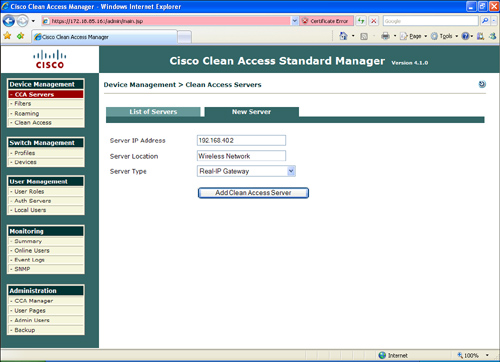
Step 4. Enter a server location description. The description can be any word or phrase that describes the location of the CAS. In this example, the location description is Wireless Network.
Step 5. The goal in this example is to configure the CAS in Real-IP gateway mode. Choose Real-IP Gateway from the drop-down menu.
Step 6. Click Add Clean Access Server.
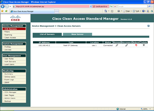
Step 7. To access the CAS, click the Manage icon under Device Management > CCA Servers, as illustrated in Figure 8-28.
Figure 8-28. Accessing the CAS via the CAM
Step 8. Verify the IP addressing information, and verify that the CAS is configured with the Real-IP Gateway option by clicking the Network tab, as shown in Figure 8-29.
Figure 8-29. Real-IP Gateway Configuration

Step 9. In this example, the trusted interface IP address is 192.168.40.2, and the default gateway is the Cisco ASA (192.168.40.1). Enter this information under the Trusted Interface section, as illustrated in Figure 8-29.
Step 10. Enter the IP address information for the untrusted interface. In this example, the untrusted interface IP address is 10.10.10.2, and the default gateway is 10.10.10.1. Both the trusted and untrusted interfaces are configured with a 24-bit subnet mask (255.255.255.0).
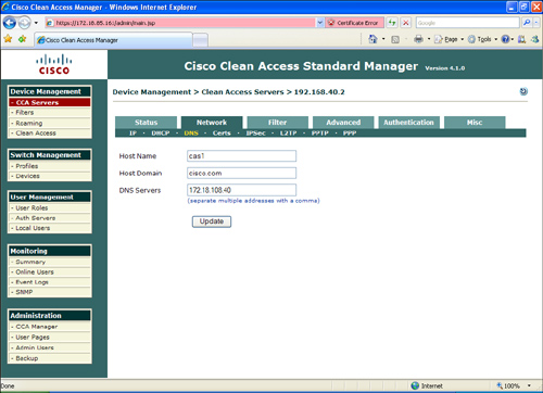
Step 11. Enter your DNS information under the DNS section, as illustrated in Figure 8-30. In this example, the CAS name is cas1, the domain name is cisco.com, and the IP address of the DNS server is 172.18.108.40.
Figure 8-30. Entering DNS Server Information
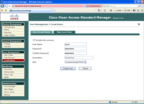
Step 12. In this example, you will create two users: guest and employee1. To create the local database, navigate to User Management > Local Users and enter the user information, as illustrated in Figure 8-31.
Figure 8-31. Adding Local Users
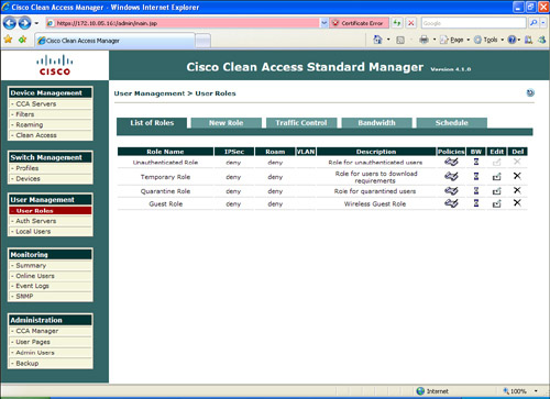
Step 13. The next step is to create the user roles. To enter a new user role, go to User Management > User Roles > New Role and enter the user role information, as illustrated in Figure 8-32.
Figure 8-32. User Roles

In Figure 8-32, the guest user role is configured. The user role name is Guest Role, and the role description is Wireless Guest Role. For guest users, at the After Successful Login Redirect to field, click to choose this URL, and enter the URL to which you want the guest user redirected. In this case, guest users will be redirected to a site called guestaccess.cisco.com with further instructions and disclaimers. All other options are left with default values.
Step 14. You can configure traffic policies to be applied to each user role by clicking the Policies icon by the specific role, as illustrated in Figure 8-33.
Figure 8-33. User Role Policies
Step 15. By default, all traffic is denied. To enter a new policy, click the Add Policy link, as illustrated in Figure 8-34.
Figure 8-34. Adding a New Policy

Step 16. Enter the policy information. In this example, all guest users are allowed to access the Internet via HTTP (TCP port 80) and HTTPs (TCP port 443). DNS traffic (UDP port 53) also needs to be allowed. Figure 8-35 shows how to configure a new policy to allow HTTP traffic.
Figure 8-35. Allowing HTTP for Guest Users

Step 17. All internal traffic is denied. In this case, all internal networks can be summarized into two major subnets: 192.168.0.0/16 and 172.18.0.0/16. Figure 8-36 shows how all the guest user policies are configured.
Figure 8-36. All Guest Users Policies

Notice how traffic to HTTP and HTTPS to all destinations is allowed by the first few policy entries. This is done because you cannot map the whole Internet for guest users. However, specific deny statements for all UDP and TCP traffic to internal networks are denied. In addition, a catch-all deny statement is included at the end.
You can assign users to different roles by editing the previously created users.
Step 18. Configure a host-based policy for access to remediation sites when users are quarantined. Navigate to User Management > User Roles > Traffic Control > Host and choose Agent Quarantine Role in the drop-down menu, as illustrated in Figure 8-37. Then select the sites you want your quarantined clients to be able to access for remediation.
Figure 8-37. Host-Based Policy for Remediation Access
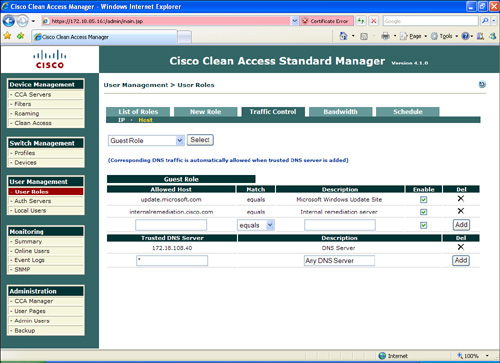
In Figure 8-37, access is allowed to update.microsoft.com (the Microsoft update site) and to an internal remediation server.
Step 19. You can create or customize a login page for the wireless users by going to Administration > User Pages and choosing Add at the Login Page tab. You can edit the web login portal page content by going to Administration > User Pages > Login Page > Edit > Content.
Step 20. To enable basic network scanning for guest user workstations, go to Network Scanner > Scan Setup to determine which user role and operating system to use. This is illustrated in Figure 8-38.
Figure 8-38. Scanner Setup
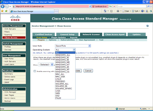
Step 21. Select the operating system options under the Plugins, Options, and Vulnerability tabs.
Step 22. You can also configure a user agreement page for web login users by navigating to the User Agreement tab.
Step 23. To establish employee roles for posture assessment, you must create a requirement rules mapping by going to Device Management > Clean Access > Clean Access Agent > Requirements > Requirement-Rules. For instance, a user can choose to perform Windows HotFixes checks for Windows-based systems.
Step 24. For employees, you should require the use of the NAC Agent (Clean Access Agent) by clicking Require use of Clean Access Agent.
After users are successfully logged in, you will see them under Monitoring > Online Users.
WLC Configuration
This section includes the steps necessary to configure the WLC for the NAC Appliance solution to work. Complete the following steps to configure the WLC.
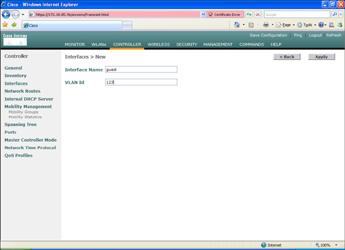
Step 1. As a best practice, it is recommended that you configure separate VLANs for guest and internal users. To do this, you need to configure two new pseudointerfaces. Log in to the WLC, navigate to Controller > Interfaces, and click New to add a new interface. Enter the name for the new interface and the VLAN you want to assign. This is illustrated in Figure 8-39. In this example, the interface for guest users is called guest and assigned to VLAN Id 123.
Figure 8-39. Adding a New Dynamic Guest Interface in the WLC
Step 2. The next screen (shown in Figure 8-40) allows you to enter the interface configuration parameters, such as IP address, subnet mask, default gateway, DHCP server information, and others. In this case, the guest interface is configured with the IP address 10.20.1.2 with a 24-bit subnet mask. The default gateway and DHCP server is 10.20.1.1.
Figure 8-40. WLC Guest Interface Configuration

Step 3. Add another interface for employees (internal users).
Step 4. Under Controller > General, make sure that Layer 3 is selected in the LWAPP Transport Mode drop-down menu, as illustrated in Figure 8-41.
Figure 8-41. LWAP Setting
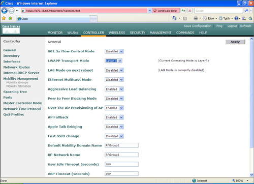
Step 5. In the Default Mobility Domain Name field, enter RFGroup1.
Step 6. Create a guest wireless LAN interface named guest and assign an SSID. (In this example, we also name it guest.)
Step 7. Configure the WLAN with open authentication and DHCP address assignment required. Enter guest as the wireless LAN interface SSID under the WLANs > Edit window. Click the check box to require DHCP Addr. Assignment, as illustrated in Figure 8-42.
Figure 8-42. Guest WLAN Configuration

Step 8. Repeat Steps 6 and 7 to create and configure a WLAN for internal users.
Step 9. To add the RADIUS server information for 802.1X authentication, navigate to Security > AAA> RADIUS Authentication. In this case, you use the same server that you configured previously in this chapter (172.18.85.181).
Step 10. The CAS uses RADIUS accounting packets to trigger the security posture of wireless users. Configure the CAS as the RADIUS Accounting server by going to Security > AAA> RADIUS Accounting > New. Add the CAS information, as illustrated in Figure 8-43.
Figure 8-43. Adding the CAS as a RADIUS Accounting Server

After you complete these steps, you will be able to authenticate using a wireless client. Guest users will be redirected to a web-based login, and regular employees will use the Cisco Clean Access Agent to connect to the network.
Summary
Wireless access is a core part of the infrastructure in most organizations. When developing a wireless implementation, take into consideration the unique security challenges that wireless connectivity brings. Implementing best practice wireless security techniques is a must for any organization. This chapter included best practices when deploying wireless networks. It also covered different types of authentication mechanisms, including 802.1x. In addition, it included an overview of LWAP, location services, MFP, and other wireless features that need to be taken into consideration when designing security within your wireless infrastructure.
This chapter also covered step-by-step configuration examples of the integration of IPS on Cisco wireless networks. In addition, it provided guidance on how to integrate the Cisco NAC Appliance and the Cisco Unified Wireless Network solution.