
Vibration Energy Harvesting System
Many environments, such as highways, railways, and so on, are subjected to ambient vibration energy that is not commonly used. To use these ambient vibrations as a power source, many researchers have successfully built and tested three basic methods for generating electrical energy from this vibration energy source: electromagnetic induction [48], electrostatic generation [97], and piezoelectric materials [98]. While each of these techniques can provide a useful amount of energy, piezoelectric materials have received the most attention due to their ability to directly convert applied strain energy into usable electric energy and the ease at which they can be integrated into a system [98]. Unlike the electrostatic and electromagnetic approaches, which require a complex “two-part” design (the two plates of the variable capacitor in the electrostatic configuration, the coil and the magnet in the electromagnetic one), the piezoelectric approach is relatively simpler in design and implementation. Plus, Roundy et al. [99] demonstrated that the piezoelectric type has the highest energy density. Based on these positive findings, the piezoelectric approach has been employed in this vibration energy harvesting (VEH) research for powering the electrical load.
Piezoelectricity is the ability of some materials (i.e., crystals) to convert mechanical energy into electrical energy and the inverse [100]. When an external force mechanically strains the piezoelectric material, the material becomes electrically polarized, and the degree of polarization is proportional to the applied strain. The opposite effect is also possible: When the piezoelectric material is subjected to an external electrical field, it is deformed. The relationships between the applied force and the subsequent response of a piezoelectric material depend on three factors [101]: (1) the dimensions and geometry of the material, (2) the piezoelectric properties of the material, and (3) the directions of the mechanical or electrical excitation. The first relationship is straightforward. As for the second relationship, the behaviour of piezoelectricity can be modelled with the following constituent equations:
(4.1) |
(4.2) |
Based on the describing electromechanical expression of a piezoelectric material expressed in Equation 4.1, the electrical displacement D relates with the mechanical stress X applied, and the electrical field E is generated. The proportionality constants are the d coefficient and the dielectric constant ∈X measured at constant stress. As for the expression in Equation 4.2, it relates the mechanical strain developed when an electrical field E is applied with the field, and the mechanical stress X is developed. The proportionality constants are the same d coefficient and the elastic compliance sE measured at a constant electrical field. For the third relationship, according to Gonzalez et al. [79], the piezoelectric materials are visualized as 3D (three-dimensinal) structures where the mechanical and electrical magnitudes can be applied or measured in any of the three axes. The axes are defined in Figure 4.1 where the impact-based piezoelectric generators in parallel and transverse modes of operation are illustrated.

FIGURE 4.1
Parallel and transverse tension modes of operation for a piezoelectric generator. (From J.L. Gonzalez, A. Rubio, and F. Moll, “Human-powered piezoelectric batteries to supply power of wearables electronic devices,” International Journal of the Society of Materials Engineering for Resources, vol. 10, no. 1, pp. 34–40, 2002 [79].)
In this VEH research, two types of piezoelectric generators that are designed to harvest impact or impulse forces are explored: (1) the piezoelectric push-button igniter described in Section 4.1 and (2) the prestressed piezoelectric diaphragm material described in Section 4.2. With reference to Figure 4.1, the piezoelectric igniter operates in the parallel compression mode or 33-mode of operation where the electrical field is generated (i.e., axis- 3) across the same axis where an external mechanical force F is applied to create a mechanical resonance in the piezoelectric element [79]. As for the other type of piezoelectric generator, which uses a prestressed piezoelectric diaphragm material, a transverse mode or 31-mode of operation as shown in Figure 4.1 is considered [102]. The mechanical strain applied on the piezoelectric material is perpendicular to its output electrodes, so the surface where the charge is collected and the surface where the force is applied are independent. When the piezoelectric material is excited in 31-mode operation, elongation or compression normal to the 1 axis is induced; hence, an electric field normal to the 3 axis is generated.
Impact-based piezoelectric energy harvesting has been widely discussed in the literature to harvest waste kinetic energy from human motions, ammunitions, and so on for powering low-power electronic devices. According to Beeby et al. [103], the earliest example of a piezoelectric kinetic energy harvesting system extracted energy from impacts. Umeda et al. [104] pioneered the analysis of the energy generated by the impact of a steel ball on a piezoelectric membrane. Initial work explored the feasibility of this approach by dropping a 5.5-g steel ball bearing from 20 mm onto a piezoelectric transducer. Keawboonchuay et al. [105] studied a high-power impact piezoelectric generator that can be incorporated into ammunitions. Subsequently, impact coupling of a piezoelectric transducer designed for use in human applications was described by Renaud et al. [106]. The authors presented some analysis related to the impact harvester, which was comprised of an inertial mass confined within a frame but free to slide along one axis, for human applications and assessed the relevance of such a system for harvesting energy from large-amplitude and low-frequency excitations. Energy is generated when the sliding mass strikes steel/PZT (lead zirconate titanate) cantilevers located at each end of the frame. Several studies on direct straining of, or impacting on, a piezoelectric element for human applications have also been reported. One of the earliest examples of a shoe-mounted generator incorporated a hydraulic system mounted in the heel and sole of a shoe coupled to cylindrical PZT stacks [107]. The hydraulic system amplifies the force on the piezoelectric stack whilst reducing the stroke. A subsequent device was developed at the Massachusetts Institute of Technology (MIT) in the 1990s [81] as an insole in a sports training shoe; the bending movement of the sole strains both polyvinylidene fluoride (PVDF) stacks to produce electrical power.
4.1 Impact-Based Vibration Energy Harvesting (VEH) Using a Piezoelectric Push-Button Igniter
A self-powered push button is an interesting application that utilizes impact-based energy harvesting [28] for powering a self-powered remote controller. In 1956, Robert Alder designed a self-powered remote control called the Space Commander for Zenith televisions. It featured a set of buttons that struck aluminum rods to produce ultrasonic waves when decoded at the television receiver would change channels appropriately. Joe Paradiso and Mark Feldmeier took this theme further in 2001 by using a piezoelectric element with a resonantly matched transformer and conditioning electronics that, when struck by a button, generate electrical power to run a digital encoder and a radio transmitter [108]. Furthermore, a German company, EnOcean [109], developed some self-powered radio transmitters, energized by a bi-stable piezoelectric cantilever that snaps when pressed, and are conditioned by a switching voltage regulator. In this impact-based VEH research, the proposed piezoelectric push-button igniter system, as depicted in Figure 4.2, is designed to be compact, simple, low cost in terms of power density and energy requirements, and at the same time able to harvest sufficient energy from the impulse force generated by human pressing to power the remote controller.

FIGURE 4.2
A block diagram of a self-powered wireless RF transmitter.
Referring to Figure 4.2, the key components of a self-powered wireless transmitter system include a micropower impact-based piezoelectric generator, an energy storage device, a power processing unit (PPU), and a radio transmitter. When a small mechanical force is depressed on the piezoelectric push button, the kinetic energy is harvested by the piezoelectric igniter and converted into electrical energy. The electrical energy is temporarily stored in an energy storage device like a capacitor or battery and then regulated by the PPU into regulated output voltage. After this, the regulated direct current (DC) power provides energy for the radio-frequency (RF) transmitter circuit to perform serial transmission via the radio transmitter to communicate with the environmental sensors, control, and actuating systems deployed in the smart environment.
4.1.1 Piezoelectric Push Button
Piezoelectric push buttons shown in Figure 4.3 have been widely used in industries for several purposes. One example is the integration of a push button in an igniter for gas lighting; it generates very high voltage at very low mechanical impact force, and this high voltage is applied to an air gap to generate an electric arc. Referring to Figure 4.3, the piezoelectric igniter consists of a cylindrical metal base that connects to the negative wire, and the other positive wire is internally connected to the piezoelectric element. A depressible ignition button-like structure is found on the top part of the igniter body. When the piezoelectric push button is depressed, a spring inside will be compressed. When the pressure exceeds a threshold, the spring-loaded hammer will be released, which delivers a dynamic mechanical force to compress the piezoelectric element as illustrated in Figure 4.4. Referring to Figure 4.4, the external force mechanically strains the internal piezoelectric element; these polarized unit cells shift and align in a regular pattern in the crystal lattice. The discrete dipole effects accumulate, developing an electrostatic potential between opposing faces of the element [110].
In the parallel mode of operation [79], the electrical field is generated (i.e., axis-3 in this case as shown in Figure 4.4) across the same axis where the external mechanical stress, σ, is applied by the spring-loaded hammer. The short circuit charge displacement Q3 generated on the surface of the piezoelectric generator of area A = L ∗ W along the axis-3 can be expressed as
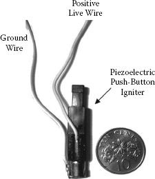
FIGURE 4.3
A piezoelectric push-button igniter and its components.
(4.3) |
where L is the length along the axis-2 and W the width along the axis-1. The applied stress, σ, is a function of the applied mechanical force, F, and the surface area, A. The piezoelectric voltage constant, g, is the quotient of the electric field, generated E, and the stress, T, applied [79]. Additionally, the electric field is a function of the open circuit voltage, Voc, of the piezoelectric generator divided by its thickness, T, hence the open circuit electric field Eoc generated [111] can be expressed as
(4.4) |
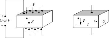
FIGURE 4.4
Parallel compression on a piezoelectric element. (Form Piezo Systems, Inc., “Introduction to piezo transducers,” http://www.piezo.com/tech2intropiezotrans.html, accessed on May 17, 2010 [111].)
Knowing that the piezoelectric charge constant, d, [79] is given as
(4.5) |
where ∊0 is the permittivity of free space (8.85 x 10⁻¹²) and is the permittivity of the material at constant stress. It can be demonstrated that the piezoelectric generator can be modelled as a capacitor of value [111],
(4.6) |
Hence, the electrical power P3 generated by the piezoelectric generator can be calculated as the rate of the energy stored in the capacitor, which is given by
(4.7) |
where f is the frequency of the vibration. The derived relationship shows that for a given piezoelectric material of fixed area A and thickness T the generated electrical power P under the force F is dependent on the piezoelectric material charge constant d and voltage constant g. In order to obtain a high-performance impact-based piezoelectric generator, the piezoelectric ceramic element with high figures of merit (d and g) has to be selected. In addition, the volume of the piezoelectric element and the amount of stress exerted on the element are also the key factors to be considered in converting mechanical input to electrical energy.
The next step is to determine the electrical characteristic of the piezoelectric push-button igniter to facilitate the design of the PPU for powering the wireless transmitter load. The dimension of the piezoelectric push button used in this research is 35 mm long and 5 mm in diameter and has a deflection of 4.5 mm at a maximum force of 15 N. When an actuation force of 15 N is applied onto the piezoelectric push button [108], the internal hammer is released to strike the piezoelectric element as shown in Figure 4.5. The excitation force of the hammer generates a pressure wave on the piezoelectric element to output a very high voltage of 6 kV. The high output voltage generated follows closely to an alternating current (AC) signal due to dynamic polarization of the piezoelectric element. Each strike of the hammer creates a mechanical resonance in the piezoelectric element as illustrated in the zoomed version of Figure 4.5 whereby 10 small AC voltage pulses are observed. Subsequently, about nine more iterations of the hammer striking the piezoelectric element are observed in Figure 4.5, and the harvested energy pulses from the piezoelectric push-button generator occur for a short time span of around 1.5 ms.
Since each input actuation force provided by the human is not continuous but rather behaves in a pulse-like manner, the output voltage will gradually attenuate following the attenuation of the mechanical vibrations in the piezoelectric element. Hence, it is critical to ensure that the harvested energy is sufficient to transmit a few packets of information through the RF transmitter in a wireless manner. Figure 4.6 shows the 12-bit data encoded by a HT-12E encoder to be sent out by the RF wireless transmitter.

FIGURE 4.5
A piezoelectric push-button igniter.
The encoder first generates a synchronization starting bit following an 8-bit address [1000 0000] and 4-bit data [0101] sequence serially. The address/data pins of the HT-12E encoder have been prefixed to the [1000 0000 0101] sequence to be sent to the transmitter. The key for low energy consumption lies in the fact that in many applications, transmitters are idle most of the time. Therefore, the proposed concept of piezoelectric push-button power generation fits snugly since transmission will only be required when the push button is being depressed, like the case of typical wireless remote controllers. In order to power the RF transmission operation, which takes approximately tens of milliseconds for a complete 12-bit information transmission as shown in Figure 4.6, the electrical energy has to be stored properly in order to ensure complete transmission operation even when the external power source is temporarily unavailable. During this time, the transmission operation is constantly consuming energy until the process is completed where only a minimal amount of energy is needed by the transmitter circuit during the standby mode.

FIGURE 4.6
An enlarged diagram of the 12-bit data sent out by the HT12-E encoder.
4.1.2 Energy Storage and the Power Processing Unit
The PPU converts the AC output voltage from the piezoelectric generator into a DC source through AC-DC full-wave diode bridge rectification. After this, the capacitor connected across the output of the full-wave bridge rectifier doubles as a storage device since energy from the piezoelectric generator is finite and occurs for only a short pulse as well as a filter, which helps to smooth the voltage ripples in the rectified DC voltage. Hence, by choosing a capacitor with a higher capacitance value, the rectified DC voltage can be stepped down to a lower level effectively by the capacitor; at the same time, the capacitor can better smooth the DC voltage and also provide more energy storage for the harvested energy. Thereafter, the capacitor output voltage, the unregulated DC voltage, is further regulated by a voltage regulator circuit into regulated DC voltage.
Due to several design constraints imposed on the impact-based VEH system like miniature size, simple design, and low-cost requirements, a simple voltage regulator is used. According to Dewan et al. [112], if the voltage difference between the input and output of the linear voltage regulator is kept to a minimum, then the linear regulator’s efficiency is maximized. This is because a small amount of voltage is dropped across the voltage regulator; hence, little energy is wasted. A switched-mode voltage regulator, on the other hand, suffers from ripples in the output voltage due to its switching rates and has a very high quiescent current compared to a linear voltage regulator, especially in low-power operations where load currents are very low, on the order of microamperes. Although a switch-mode voltage regulator is relatively more complex, it has some superior advantages over a linear regulator, like high power conversion efficiency, voltage step-up and step-down capability, and more. After considering both the advantages and the disadvantages of applying the two types of voltage regulators for research, a linear regulator is more suitable for this VEH research work.
The schematic diagram of the proposed piezoelectric energy harvesting system is shown in Figure 4.7. Referring to Figure 4.7, the principle of operation of the piezoelectric energy harvester for powering a self-powered wireless transmitter is illustrated. When the piezoelectric push button is depressed, around 5 to 7 kV of AC voltage is generated. The generated AC voltage is rectified into DC voltage by the full-wave rectifying diode bridge, and the DC voltage is stored temporarily in the 2.2-μF capacitor. The presence of the capacitor is not only to store harvested energy but also to help clamp down the DC voltage to about 8 V and to smooth the DC voltage to constant voltage. The unregulated DC voltage from the capacitor is regulated by the MAX666 linear regulator. The regulated output DC voltage of MAX666 is 3.3 V, which is then used to operate the HT-12E encoder to transmit 12-bit address/data information via the radio transmitter. The whole piezoelectric push-button transmitter system is mounted on a printed circuit board (PCB) with a total area size of 25 cm2, and its assembled prototype [113] is shown in Figure 4.8.
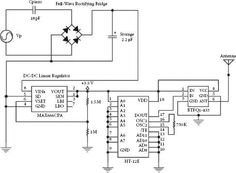
FIGURE 4.7
A circuit schematic of a piezoelectric energy harvesting circuit.
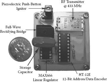
FIGURE 4.8
Photograph of the assembled prototype showing the key components.
Key components of the system are listed in Figure 4.8. They include the piezoelectric push-button igniter, full-wave rectifying diode bridge, 2.2-μF storage capacitor, MAX666 linear regulator, HT-12E 12-bit address/data encoder, and a RF transmitter operating at 433 MHz. A Singapore 50-cent coin has been included for relative size comparison. Comparing the sizes between the piezoelectric push-button transmitter system and the coin as illustrated in Figure 4.8, the requirement of miniature design for the system has been achieved. In addition, the whole assembly is very light, weighing about 12 g. Taking into account all the components used in the circuit design, the total cost of assembly was less than SGD$35.00, which meets the low manufacturing cost requirement. Hence, the small size, light weight, and low-cost features of the piezoelectric push-button transmitter system make it suitable for many wireless applications like a wireless remote controller.
Several experimental tests were conducted to evaluate the performance of the designed piezoelectric push-button igniter system. The open-circuit AC voltage generated by the piezoelectric igniter as seen in Figure 4.9 is fed into a full-wave diode bridge rectifier, where the AC voltage is converted into DC voltage, and then the DC voltage is stored in the capacitor. The DC voltage waveform at the output of the diode bridge rectifier is shown in Figure 4.10. Referring to Figure 4.10, it can be seen that the peak DC voltage is around 600 V. The zoomed view of the output DC voltage of the full-wave diode bridge rectifier is shown in the bottom waveform of Figure 4.10.

FIGURE 4.9
An open circuit voltage of piezoelectric push-button igniter.

FIGURE 4.10
Output DC voltage of the full-wave diode bridge rectifier.
The sawtooth waveform observed in Figure 4.10 is the rectification of the AC voltage pulses of the piezoelectric push-button igniter. After the AC-DC rectification, the unregulated DC voltage is filtered by a parallel connected capacitor of 2.2 μF added to provide some smoothing effects on the DC voltage as well as to store the harvested energy. The waveforms of the capacitor and the output of the linear regulator are shown in Figure 4.11 where Channel 1 is the DC voltage across the capacitor and Channel 2 is the regulated voltage output from the linear regulator voltage.
It can be seen from Figure 4.11 that the maximum voltage accumulated across the capacitor is 7.84 V, and the capacitor is discharged completely in 300 ms. Using the formula
(4.8) |
the amount of electrical energy that is harvested after the piezoelectric push button is depressed is 67.61 μJ. As for the linear regulator, the output DC voltage is regulated at 3.3 V, and it remains constant for around 50 ms before it starts to drop to zero with respect to the capacitor discharge rate. Hence, the challenge is that within the 50 ms of regulated DC 3.3 V, the 12-bit address/data information has to be transmitted from the HT-12E encoder via the radio transmitter. As mentioned, the harvested energy occurs only for a short pulse through actuation of the piezoelectric pulse generator; therefore, in evaluating the performance of our energy harvesting circuit design, the voltage waveforms of the discharging capacitor together with the DC linear regulator and the 12-bit address/data information transmitted need to be examined closely.
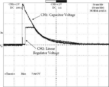
FIGURE 4.11
Voltage waveforms of a capacitor and output of a linear regulator.

FIGURE 4.12
Output waveforms of a capacitor discharge, 3.3-V DC regulation, and 12-bit address/data transmission.
The results obtained from the energy harvesting circuit design are illustrated in Figure 4.12. Channel 1 in the figure represents the discharging waveform of the storage capacitor. Channel 2 shows the 3.3-V DC signal output waveform from the linear regulator, and Channel 3 represents the 12-bit address/data information transmitted by the HT-12E encoder via the radio transmitter. The energy consumption of the RF unit is calculated based on the operating and standby modes of the RF unit. The total latency time required for 1 digital word transmission is 20 ms; the time during which transmission is active is 10 ms, and the time during which transmission is on standby is 10 ms. During RF unit operating mode and standby mode, the currents drawn by the transmitter are 8 mA and 0.1 μA, respectively. Therefore, the peak powers required during transmission and standby are 2.64 mW and 0.33 μW, respectively. The total maximum energy required for 1 digital word transmission is then 26.4 μJ. Knowing that the harvested electrical energy is 67.61 μJ and the energy required to transmit 1 digital word is 26.4 μJ, it can be calculated that around 2.5 digital words can be transmitted with one push of the piezoelectric push-button igniter. This is verified in Figure 4.12. As shown in the figure, the regulated DC voltage from the linear regulator is sufficient to make at least two complete 12-bit information transmissions at 3.3-V DC. It can therefore be seen that the piezoelectric push-button energy harvesting circuit is able to harness enough energy for two complete transmissions at a constant 3.3-V DC.
In this impact-based VEH research, special interest is placed on using a piezoelectric push-button igniter as the energy harvester because it is easy and simple to harvest mechanical force energy from human beings. An energy harvesting circuit design for the piezoelectric push-button generator was proposed and implemented efficiently for a wireless RF transmitter. This self-powered wireless transmitter is capable of transmitting a 12-bit digital word information using the mechanical force energy of 15 N harvested from depressing the push button attached to the energy harvesting circuit. Experimental results showed that when the piezoelectric push button is depressed, 67.61 μJ of electrical energy is harvested, and it is sufficient to transmit information for at least 2 complete 12-bit digital words via the RF transmitter unit, which consumes 26.4 μJ of energy for 1 digital word transmission. As such, this research work has successfully demonstrated the feasibility of a completely self-autonomous piezoelectric push-button wireless RF transmitter, which optimizes effectiveness in size, weight, and cost.
4.2 Impact-Based VEH Using Prestressed Piezoelectric Diaphragm Material
Cabling has always been a hassle for applications like the design of a house’s lighting system with the need to draw cables from lamps and bulbs to the switches mounted on the walls of the house. The need for in-wall cabling will often result in high costs for the homeowner. Undesirable recabling implications may also arise over time should the cable become faulty. Other than that, the conventional method to power onboard wireless communication and electronic circuitries of the controllers are normally alkaline or rechargeable batteries. One major drawback with these commercially available battery-operated remote controllers is that batteries have a limited energy supply. Every time the remote controllers operate, the energy level of the internal battery source depletes, until some time later when the controllers are no longer able to function. As such, regular maintenance of the controllers is required in order to not create any disruption to the user. To address this issue, an impact-based energy harvesting system using a piezoelectric igniter has been carried out as discussed in Section 4.1. It is a simple and viable solution to harvest mechanical force energy from human beings to sustain the operation of the remote controller. Whenever someone depresses the push-button mechanism, a high-impact force coming from the internal hammer strikes onto the piezoelectric material, which consists of a stack of piezoelectric ceramic layers, and some electrical energy is generated. However, under this high-stress cycling, it is mentioned by Kim et al. [114] that the piezoelectric material stack of the push-button igniter may develop interfacial cracking or buckling, thus shortening its lifetime. In addition, the piezoelectric igniter suffers from two more drawbacks: (1) high input force is required to release the hammer of the push-button mechanism and (2) high output voltage and low output current of a few kilovolts and microamperes are generated due to the piezoelectric stack structure. Because of that, the design and implementation of the power management circuit become complicated.

FIGURE 4.13
A basic set of a LightningSwitch with one transmitter (left) and one receiver (right).
To overcome these drawbacks associated with the piezoelectric igniter system, another type of impact-based 31-mode piezoelectric generator, operating in mechanical nonresonance, has been explored to harvest impact or impulse forces from human pressing. There are several types of impact-based piezoelectric generators described in the literature [104, 105 and 106], and there are also some companies like LightningSwitch [115] that apply this piezoelectricity technology on commercial products like a wireless control switch. The self-powered wireless control switch with energy harvesting capability has two significant advantages: (1) flexibility in positioning the power electronic devices at any part of the deployment area that is within the RF communication zone and (2) elimination of the high manpower and material costs in laying wiring cables between the switches and the devices. A basic set of LightningSwitch, consisting of one transmitter and one receiver, is shown in Figure 4.13. Inside the transmitter (see Figure 4.14), LightningSwitch employs a uniquely assembled cantilever design to mount and excite the commercially available piezoelectric transducer material for harvesting vibrational energy generated from human pressing.

FIGURE 4.14
Internal design of a LightningSwitch transmitter.
Referring to Figure 4.14, whenever a user depresses the commercially available switch equipped with the energy harvesting feature, the harvested impact force is not directly applied to the energy harvesting material (i.e., piezoelectric PZT material), instead it is transferred from the human depressing point through an in-built mechanical cantilevered structure to indirectly activate the material. The custom design mechanical structure translates the applied mechanical force onto the edge of the cantilevered piezoelectric transducer material. As the mechanical force is applied onto the piezoelectric material, it bends until the mechanical structure releases the piezoelectric material; thus, mechanical oscillating vibration is generated. The vibration energy is then converted into electrical energy using the cantilevered piezoelectric material. In the LightningSwitch design, the whole energy conversion process involves many different stages from human depressing force to harvested electrical energy. During these conversion stages, a certain portion of the harvested mechanical energy is lost due to an energy efficiency drop at each of the individual stages. In addition, the uniquely assembled cantilever design used in LightningSwitch products, which employs the extra complicated mechanical structure design, would also incur more cost to develop and manufacture it.
Unlike the commercially available products and research prototypes, which employ a complicated energy harvesting mechanism to excite its 31-mode piezoelectric generator, a relatively new concept of energy harvesting from depressing a prestressed piezoelectric diaphragm material has been proposed in this research to generate electrical power for a wireless RF transmitter and its power management circuit to switch on/off electrical appliances such as lighting, fans, and so on, in a wireless manner. The main objective of this research is to fulfill a self-powered switch with a less-complicated as well as less-costly energy harvesting technique. This is achieved by removing the excessive components of the energy harvesting mechanism.
4.2.1 Description of Prestressed Piezoelectric Diaphragm Material
The impact-based energy harvesting mechanism used in this research is simply a prestressed piezoelectric diaphragm material manufactured by Face® International Corporation based on the THUNDER (THin layer UNimorph ferroelectric DrivER and sensor) technology originally developed by NASA in conjunction with the RAINBOW (reduced and internally biased oxide wafer) design effort [116]. The prestressed piezoelectric diaphragm material, as shown in Figure 4.15, is electrically poled in the 31 coupling mode, and it is initially curved, arc shaped, and rectangular, which elongates when a force is applied to the top of the arc. The elongation causes strain in the active material, which produces a voltage. The device is simply supported and allows for movement only in the lateral direction.

FIGURE 4.15
A diagram of the prestressed piezoelectric diaphragm material, TH7R.
As an input force is applied at the centre of the warped structure dome-shaped piezoelectric strip, a resultant tensile force is generated in the piezoelectric material along the 1-axis and voltage is harvested and poled along the 3-axis, as illustrated in Figure 4.15. Unlike the piezoelectric igniter that operates in the parallel compression mode or 33-mode of operation, this transverse configuration maximizes the piezoelectric transducer efficiency in converting mechanical energy to electrical energy in a low-force environment. The innovative part of this research is the use of the natural characteristic and construction of the prestressed diaphragm material as an energy harvesting material (its unique characteristic is that when the material is depressed, it is deformed, and it generates electrical energy) as well as a switch (its pre-stressed construction creates a bouncing reaction whenever the material is depressed at the centre).
Referring to Figure 4.16, the THUNDER piezoelectric device consists of a piezoelectric ceramic layer, PZT, and a backing metal layer, held together with a polyimide adhesive as described by Bryant [117]. Several researchers have investigated this type of device, and literature is widely available on its actuation and manufacturing details. However, very few researchers have examined its potential as an energy conversion mechanism [118]. As an energy harvesting device, few publications are available: Ramsay et al. [54] demonstrated the feasibility of utilizing the power generated in a bio-MEMS (bio-microelectromechanical system) application; Mossi et al. [119] compared different configurations of the device for actuation and energy harvesting; and Shenck et al. [46] utilized this device for harvesting energy by mounting it on a shoe. Danak et al. [120] also researched ways to optimize the design of an initially curved PZT unimorph power harvester. A mathematical model was created that predicts the power output of the device. From this model, relationships between generated charge and initial dome height, substrate thickness, PZT thickness, and substrate stiffness were established.

FIGURE 4.16
Construction of a THUNDER TH7R.
Technical Specifications of TH7R
TH7R Dimensions and Physical Properties |
||
Weight |
g |
18 |
Dimensions |
mm |
95.3 x 73.4 x 0.53 |
PZT thickness |
mm |
0.25 |
Static capacitance |
nF |
166 |
Maximum voltage |
V |
300 |
Vertical displacement |
mm |
9.55 |
THUNDER transducers are commercially available in a variety of sizes and force displacement characteristics, each with very different electromechanical characteristics. According to Danak et al. [120], the power available from a flat piezoelectric transducer under 31-mode bending excitation is generally proportional to the volume of the material and the vertical displacement induced. Therefore, while constrained by the size, comfort, and vertical displacement experienced by the human pressing, the volume of PZT piezo-ceramic is maximized when selecting the appropriate transducer. Hence, the TH7R piezoelectric device is chosen, and its technical specifications are shown in Table 4.1.
4.2.2 Characteristics and Performance of THUNDER Lead-Zirconate-Titanate Unimorph
The unique prestressed characteristic and convex shape of the THUNDER piezoelectric material is used as a natural “press-and-release” mechanical switch. The natural “press-and-release” process of the piezoelectric material illustrated in Figure 4.17 consists of displacing the transducer from its equilibrium position, reaching maximum displacement (stress), before allowing the transducer to return to its equilibrium position via the opposite direction. The change in direction of displacement, and hence direction of stress, causes a reverse in polarity, and an AC voltage is generated at the output of the piezoelectric material. The impact-based energy harvesting process seen in Figure 4.17 can be described as follows: Initially, at zero voltage state labelled as 1, the piezoelectric material is not depressed, so it can be seen from Figure 4.18 that no voltage is generated by the piezoelectric material. On depressing the material, which is illustrated by the positive voltage state labelled 2 in Figure 4.17, the material is flattened, and the electrical voltage developed across the material can be read from Figure 4.18 to be 110 V. Energy accumulated in the piezoelectric material is available for harvesting by the designed power management circuit and the connected wireless transmitter load. Similarly, on releasing the material as illustrated by the negative voltage state labelled 3 in Figure 4.17, the material bounces back to its original prestressed state, a rectified electrical voltage of 110 V is developed across the material, and energy is stored in the material for harvesting.
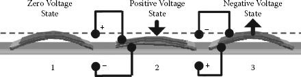
FIGURE 4.17
A depressing cycle of the prestressed piezoelectric diaphragm material.
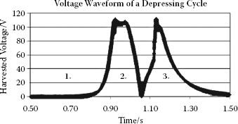
FIGURE 4.18
Voltage waveform of a depressing cycle of the prestressed piezoelectric diaphragm material.
The natural bouncing characteristic and power generation ability of the material has been utilized by this research to simplify the structure of the energy harvesting mechanism. By doing so, it is no longer necessary to have any additional mechanical structure, like the LightningSwitch case shown in Figure 4.14, to translate the human pressing force into electrical energy. This is a great advantage of this research over the commercial products available on the market. Without the need of an extra energy translation mechanism, this proposed impact-based energy harvesting mechanism using a prestressed piezoelectric diaphragm material reduces the cost of manufacturing the switch to lower than that of the more complicated LightningSwitch design. In summary, this research work, which uses a batteryless wireless control switch and prestressed piezoelectric diaphragm material, is less complicated to implement, is less susceptible to wear and tear due to less mechanical parts, and enables more cost savings than similar products available in market.
To determine the characteristic of the prestressed piezoelectric diaphragm material, different input forces—hard (∼10 N), normal (∼5 N), and light (∼1 N)—provided by a human’s thumb pressing are applied onto the piezoelectric material. For each applied input force, the output AC voltage Vac of the piezoelectric material is rectified by a diode bridge into DC voltage Vdc for various loading resistances Rload to calculate the equivalent electrical energy being harvested. In this case, the voltage drop across the diode bridge is very low as compared to Vac; hence, it is reasonable to neglect the voltage loss in the diodes. Since the voltage generated by the piezoelectric material is time-variant, as can be seen in Figure 4.18, the electrical energy harvested Eharvested has to be calculated based on the following equation:
(4.9) |
where V(t) is the instantaneous voltage taken from the generated voltage waveform. In order to solve the integral, the oscilloscope readings are extracted into an ASCII file and analyzed using Microsoft Excel. Figure 4.19 demonstrates the method of estimating Eharvested based on the integral of V (t) by using a first-order approximation.
Referring to Figure 4.19, since the oscilloscope reads in discrete measurements, the integral of V (t) is estimated by approximating a straight line joining all the measured points, resulting in many trapeziums of equal width, and summing the areas of each trapezium. Hence, the integral of V (t) can be calculated as follows:
(4.10) |
The accuracy of the estimation depends on the sampling frequency. On average, the sampling frequency of the oscilloscope is 5 kHz; hence, each interval is 0.2 ms, which is sufficiently accurate for approximating the integral of V (t) and therefore the electrical energy harvested Eharvested. Based on Equations 4.9 and 4.10, the maximum harvested energy from the piezoelectric material with internal capacitance Cpiezo of 164 nF is tabulated in Table 4.2 for various input forces provided by a human’s thumb pressing.
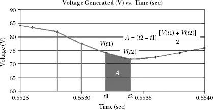
FIGURE 4.19
Estimating integral using a first-order approximation.
Maximum Energy Available for Harvesting under Various Input Forces
Input Force |
Peak Voltage (V) |
Time Span (s) |
Energy Harvested mJ |
Light / 1 |
73.3 |
1.112 |
0.88 |
Normal / 5 |
86.7 |
0.846 |
1.23 |
Heavy / 10 |
112.5 |
0.721 |
2.08 |
Apart from determining the optimal load condition, the optimal capacitance that maximum energy can be transferred from the piezoelectric material and stored into the external storage capacitor has to be investigated as well. In this experimental test, the load connected to the output terminal of piezoelectric material is a capacitor with capacitance values ranging from 150 nF to 33 μF. The experiments are conducted to investigate the performance of the piezoelectric material in terms of its generated peak voltage and harvested energy for different capacitor values, and their experimental results are illustrated in Figures 4.20 and 4.21.
Referring to Figure 4.20, it can be observed that the peak voltage generated across the capacitor falls with the capacitance value of the external capacitor. Based on the principle of conservation of charges, Q = CV, as the capacitance value increases, while the generated charges remain unchanged, the voltage developed across the capacitor decreases. This is the voltage clamping effect of the capacitor. Similarly, with reference to Figure 4.21, it can be seen that the electrical energy stored in the capacitor decreases as the capacitance value increases. According to Shenck [101], if there is impedance mismatch between the source capacitance of piezoelectric material and the load capacitance, energy loss is bound to occur in the energy transfer process. Hence, transferring energy from a fixed capacitor (source capacitor) to an increasingly large capacitor will result in greater mismatch and higher losses. Among the various capacitance values, 3.3 μF yields the highest stored energy of 1.1 mJ and so does its generated voltage of around 85 V. This high output voltage might be a great challenge to the design of the power management circuit. As such, it is necessary to make a compromise between the harvested energy and the generated voltage to meet the energy requirement of the wireless load.
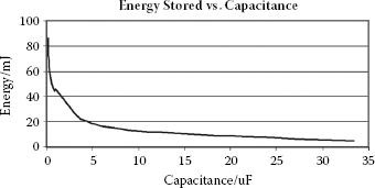
FIGURE 4.20
Peak output voltage generated at various capacitance values.

FIGURE 4.21
Harvested energy for various capacitance values.
4.2.3 Power Management Circuit
In order to determine the technical specifications of the power management circuit, the power requirements of the RF transmitter have to be determined. The transmitter power requirement is more important as it is the load to which the piezoelectric transducer supplies. Since the input voltage and current vary according to the transmission range and data rate, there is a need to determine the relationship between the input voltage and transmission range, as well as the corresponding input current. An experiment was conducted to investigate the relationship as shown in Table 4.3.
Power Consumption of RF Transmitter Load

Since the wireless control switch is designed for indoor conditions, the communication range of the transmitter is set to be around 20 m, hence the power consumption of the load read from Table 4.3 is 5 V and 1.41 mA, and the time duration to transmit three 13-bit signals is 50 ms. Apart from obtaining the power requirement of the RF transmitter load, the duration for a successful transmission is also required to determine the total energy required. Thus, the energy stored in the capacitor must be around 0.35 mJ to power the load at more than 5 V for at least 55 ms. From these specifications, with reference to Figures 4.20 and 4.21, the 10-μF capacitor is the most suitable value as it has a peak voltage of 12 V and is able to store 0.83 mJ of energy when fully charged. The principle of operation of the proposed energy harvesting system is described as follows: Whenever the switch is depressed, the mechanical force is applied onto the prestressed piezoelectric material, and some of the mechanical energy is converted into electrical energy. The harvested electrical energy from one single pressing is stored in an energy storage device until a certain preset threshold level is reached before the stored energy is released through a power management circuit to power up the RF transmitter. The RF receiver, which is connected to the electrical appliance, receives the transmitted signal and switches the appliance on/off by controlling its power supply. The schematic drawing of the proposed impact-based energy harvesting system and its power management circuit is shown in Figure 4.22.
Referring to Figure 4.22, the operation of the circuit can be explained. Charges generated by the piezoelectric transducer are first transferred into capacitor C2, while the regulator and transmitter (load) are isolated by the NMOSFET (N-metal-oxide-semiconductor field-effect transistor) N-MOS Q2, which cuts off the load ground from the source ground. The Zener diode Z1 disconnects the P-MOSFET (P-MOS) Q1 until the voltage across capacitor C1 exceeds its reverse breakdown voltage plus the threshold voltage. Once Q1 is turned on, the voltage across R2, adjustable by the potential divider formed by R1 and R2, exceeds the threshold voltage of Q2 and turns on N-MOS Q2. Thus, the source ground and load ground are connected, and C2 starts discharging to the regulator and the RF transmitter. R3 acts as the latch to ensure that P-MOS Q1, and in turn N-MOS Q2, remain on when the voltage across C2 drops below the Zener diode’s breakdown voltage. This is because once the source and load ground are connected, current flows through R3, thus maintaining a voltage at the gate of P-MOS Q1 to latch the regulator to the capacitor. The capacitor C2 stops discharging once the voltage across it falls to an extent that the voltage across R2 is below the threshold voltage of Q2. The duration of the discharge must be at least as long as the time required to transmit three successive RF signals, so that the RF receiver can acknowledge the transmission and turn on/off the electronic appliance to which it is attached.

FIGURE 4.22
Schematic drawing of the proposed impact-based energy harvesting system.
To demonstrate the feasibility of this proposed impact-based energy harvesting system using a prestressed piezoelectric diaphragm material, the hardware prototype of the batteryless wireless control switch has been implemented [121] as shown in Figure 4.23.
The component values of the schematic diagram of the proposed impact-based energy harvesting system shown in Figure 4.22 are determined with the following considerations: The first component to decide is capacitor C2. As analyzed previously, 10 μF was chosen as it has a peak voltage of about 12 V; it also has a suitable discharge time constant and stores sufficient energy for wireless transmission (∼0.836 mJ). A complementary MOSFET (N-MOS and P-MOS) is chosen as it has a low threshold voltage (1.0 V) and is conveniently placed together as a single component. Therefore, a Zener diode with a reverse breakdown voltage of 11.0 V (12 − 1 V) is selected. This ensures that the capacitor is charged to at least 12 V before it discharges to the regulator. However, a high breakdown voltage also implies that if the transducer is compressed too lightly and the maximum voltage of the capacitor fails to reach 12 V, no power will be supplied to the transmitter. R1, R2, and R3 should be as large as possible so that minimum current flows through them, and resistive losses are minimized. As mentioned, R2/(R 1 + R2) > VGS/Vreg, and with Vreg at 5.0 V, R1 = 10MΩ, R2 = 5MΩ, and R3 = 10MΩ.
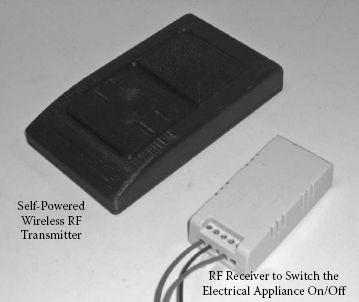
FIGURE 4.23
Prototype of a proposed batteryless wireless control switch using prestressed piezoelectric diaphragm material.
Experimental results shown in Figure 4.24 illustrate the outcome of the designed power management circuit. The voltage waveforms in Figure 4.24 are measured across the storage capacitor and the voltage regulator of the power management circuit. During one depression cycle: (1) As the human’s finger presses down onto the material, the harvested energy is stored in the capacitor and not released to the load as the source and load are disconnected. The capacitor’s voltage rises to around 7 V. (2) As the human’s finger stops pressing, energy is harvested again and stored in the capacitor. The capacitor’s voltage continues to rise to 13 V, which is more than the preset voltage level, and energy is released to the load. Once the source and load are connected, energy is supplied to the load, as can be seen in Figure 4.24 where the output voltage of the load has been regulated by the voltage regulator.
The circuit design of the receiver unit is shown in Figure 4.25. The design basically is comprised of an RF receiver circuit, a timer, and a JK flip-flop. The JK flip-flop is used to implement the simplest toggle design by connecting its inputs together. A 555 timer is used as a timing device. The decoder has a signal VT, which only turns high for a short duration when a signal from the transmitter is received. It is basically a square pulse with a width of about 0.11 s. Thus, to ensure that the JK flip-flop is triggered during the rising edge of the clock when the signal VT sends in a pulse, the frequency of the timer is set to 9 Hz. For the clock cycle waveform and the square pulse signal VT observed in Figure 4.26, the duty cycle is set to 0.5 so that the rising edge is the same for each cycle, and the timer components are related to the frequency, f = 1/0.11, by the equation: (R 1 + 2R 2) = 1. 44/(f ∗ C 1). The components chosen are R 1 = 1 KΩ, R 2 = 80 KΩ, C1 = 1.0 μF, C2 = 10 nF. Oscillator resistance (Rosc) is fixed at 82 K because the RF transmitter is operating at 433 MHz. The output of the JK flip-flop can be connected to a relay to turn the connected electrical appliances on/off.
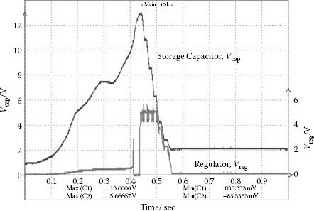
FIGURE 4.24
Voltage waveforms across a storage capacitor and voltage regulator.

FIGURE 4.25
A schematic circuit diagram of the RF receiver circuit.
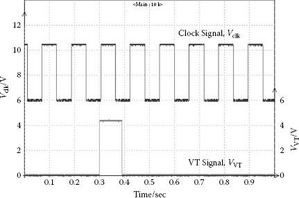
FIGURE 4.26
Voltage waveforms of VT and the clock cycle generated by a 555 timer.
Referring to Figure 4.25, it can be seen that an AND gate is added to D8 of the decoder. This means that if the transmitter sends a “high” on the corresponding data bit, it toggles this circuit. Thus, this circuit is considered to be “tagged” with the first data bit and by the same logic, four more receivers each tagged to the other four respective data bits can be built. By doing so, a single transmitter will be able to control up to four different electronic devices. In addition, this design saves the cost of having to buy one switch for every appliance, especially when it comes to appliances that are usually grouped together, such as a set of four lights in a single room. This will also eliminate the hassle of having to find the individual switch for a particular appliance, as well as having to allocate space for four switches.
In this impact-based energy harvesting research, a batteryless wireless control switch using a prestressed piezoelectric diaphragm material has been proposed for applications in warehouses, commercial buildings, and so on, to cut high wiring costs, including material, and labour expenses in laying power and signal cables from control switches all the way to the electrical appliances can be reduced tremendously. In addition, no maintenance cost and effort are required for the wireless control switches. The self-powered wireless control switch is also highly suitable for those appliances located in remote locations that are too difficult or hazardous to access and also suitable for applications where multiple electrical appliances have to be controlled simultaneously. Unlike the piezoelectric igniter system, the prestressed piezoelectric diaphragm material is more applicable for low-force environment, and its output voltage is relatively low. Since the electrical power throughput of the piezoelectric material is less than the power requirement, an energy storage and supply circuit has been implemented. By doing so, 0.83 mJ of energy is first stored in the capacitor until the preset voltage level of 12 V, and the stored energy is supplied to the RF transmitter load through a voltage regulator of 64% efficiency. From the experimental test results obtained, the harvested energy output from the voltage regulator of 0.53 mJ is sufficient to power one successful wireless transmission for a distance of 20 m.