
3
Performing Engineering on Projects (Part II)
In this chapter, I continue our summary of the key aspects of how we do engineering on projects, covering the remaining stages of the engineering life‐cycle, from “implementation” all the way through to “phase‐out and disposal.”
3.1 The Remaining Stages of the Project Life‐Cycle
In Chapter 2, we introduced the system method and then discussed the initial stages of the project life‐cycle, concentrating on the requirements and the design.
In this chapter, we discuss the remaining stages of the project life‐cycle, from implementation to phase‐out and disposal (see Figure 3.1).
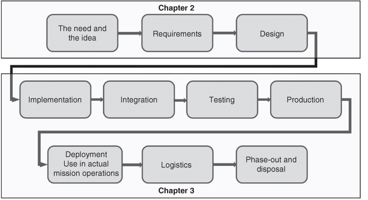
Figure 3.1 Showing in which chapter we discuss which stages of the project life‐cycle.
3.1.1 Implementation
Through the design process (described in the previous chapter), we decomposed our system into a set of pieces, each of which might involve physical structures, electronics, software, data, and other elements. Each piece might consist of only one sort of constituent (e.g. be entirely software, or be entirely a physical structure, or be entirely data, etc.), or might be a multiple of these in combination.
In the implementation phase, we build each of these individual pieces. We use the design created (and written down in the form of formal design documents) during the design phase as guidance for each piece of implementation. If we have done our decomposition well, there is relatively little interaction among the pieces as we implement them, and therefore the implementation of the pieces can proceed in parallel with each other.
Although testing of our system comes a couple of stages later, there are some basic features and characteristics of each individual piece that can and should be checked as we complete each piece; this is often called “unit testing.” I will, however, defer our discussion of this aspect until we get to the test stage, below.
3.1.2 Integration
When I was a child, I liked to build things from kits: model cars, clocks, and so forth. I would assemble all the parts into the entire entity, and then try it out and see if it worked.
For something simple like a model car, this “put it all together and only then try it out” approach might work. But for the big, complicated societal systems that we aspire to create, that approach does not work at all; there are just too many parts (especially software), and too much complexity. If you put the entire system together and only then started to try things out, when something did not work, it would be very hard to find the root of the problem; there are just too many parts, and the root cause would be hidden in all of the size and complexity of the entire system.
When people started building systems, especially systems with lots of software in them, the original concept was in fact to finish all of the implementation, then put all of the pieces together, and immediately try to conduct the formal testing of the system. It was quickly discovered that this seldom worked in a predictable and consistent fashion. The complete system, with its thousands of separate hardware parts and lots of software (nowadays, perhaps tens of millions of lines of software code), turns out to be too complex for this sort of put‐it‐together‐all‐at‐once approach to work. So, gradually, the need for a phase between implementation and testing was recognized, which we term integration.
The purpose of the integration phase is to put the parts together, at first in small subsets of the whole, gradually working one's way through the integration of ever larger subassemblies, and only stepwise reaching the goal of having the entire system.
During the integration stage, we are not yet formally testing that the system meets its requirements; instead, we are only trying to make it operate in an approximately correct fashion. We take a small subset of the system, input a representative set of system stimuli, and see what happens. We compare the outputs received to the outputs expected, and when there are differences, we go and track down the source of the discrepancy (which we can do relatively easily, because we are working with only a small subset of the entire system, and therefore we are not overwhelmed by scale and complexity) and make the necessary corrections to the implementation. We then try out our stimuli again, repeating this process until we consistently get the outputs we expected for each type of stimuli.
While we are working on integrating our small subset of the system, other teams are similarly working on integrating other small subsets. When we each seem to be getting the correct outputs from our first small subsets of the system, we put a few such subsets together into a slightly larger portion of our system, and try more stimuli. We will likely find additional errors and inconsistencies, which we can trace to a root cause and correct (we still only have a few small subsets of the system, so we are still not yet overwhelmed by scale and complexity). When our combinations of subsets seem to be working, we continue the process, reaching larger and larger scale and complexity, but doing so only after having worked out a pretty large portion of the major problems at a much smaller scale.
In essence, we are now starting upward on the right‐hand side of the “U” diagram (Figure 2.3; see the excerpt from Figure 2.3 below, labeled Figure 3.2).
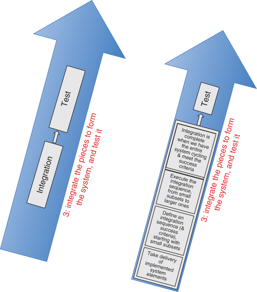
Figure 3.2 The right‐hand side of the “U” diagram. On the left, the original version (from Figure 2.3). On the right, an expanded version showing details for the integration stage.
Because the direction of flow in the diagram is now upward, from small pieces, through larger pieces, to the entire system, we say that integration proceeds bottom‐up.
In this fashion, we can spot and correct lots of problems in the design and implementation far more easily than if we wait until the entire system is assembled; it is just much easier to see the problems, and trace those problems back to a root cause, when we are dealing only with small portions of the system.
Distinguishing integration from testing has been a gigantic boon to systems engineering and engineering project management. Ironically, even though integration has proven to be important for project success, it is still often under‐resourced, in terms of time, money, people, and tools. Far too many projects still neglect the integration stage, and usually suffer greatly from that neglect.
Finding errors earlier in the process is not only easier (due to the smaller scale, as noted above), it is also far less expensive. I have seen data which says that the cost to find and fix a problem increases by about a factor of five in each successive project stage (e.g. requirements, design, implementation, integration, test, deployment, operation). This means that it costs about 1000 times as much to find and fix a problem in the deployment stage as in the requirements stage! This is a big part of why good projects are willing to spend a lot of time and money on those early project phases, especially requirements and design. It also explains why good projects are willing to spend time and money on integration: it costs five times less to find a problem during integration than during the very next stage (testing).
Another interesting and subtle aspect of integration is that the sequence you select for integration matters a lot. Figure 3.3 depicts two alternative integration sequences (A and B) for integrating nine components, which are labeled components C1 through C9.
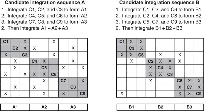
Figure 3.3 An example of the importance of how we select a sequence for integration.
In each alternative integration sequence, we first integrate the three components inside each gray box, and only after we have completed those initial integration steps do we put all nine components (e.g. all three of the gray boxes) together for a larger integration step.
In the sequence on the left, we integrate C1, C2, and C3 first; another team is integrating C4, C5, and C6; and a third team is integrating C7, C8, and C9. When all three teams have completed their integration of their three components, we then put the three subassemblies together, and have all nine components together in the integration activity.
You will recall that in the design process we generally desire loose coupling between elements; similarly, in selecting the order of integration, we want to select an order of integration that mostly involves loose coupling between elements. That is, we want to exercise the most demanding interactions within the boundaries of our initial integration structures.
In both drawings, the off‐axis Xs show where there are component‐to‐component interactions.
In candidate integration sequence A (on the left in the figure), the off‐axis interactions fall largely outside the initial 3 × 3 integration steps (labeled A1, A2, and A3). In candidate integration sequence B (on the right in the figure) – you can check that the interactions defined between the components C1 through C9 are exactly the same as in the left‐hand candidate – many more of the interactions between the components fall within the initial 3 × 3 integration steps (labeled B1, B2, and B3). That way, we have the chance to find and fix more problems during the simpler initial integration step. In my view, the right‐hand candidate is a superior choice for an integration sequence.
I call this representation a coupling matrix. It can be used as a tool to help you select an appropriate integration sequence.
Integration needs specialized tools: drivers, simulators, data sets, recording and analysis tools, and so forth. Make sure that you allocate time, people, and money at the beginning of the project to build these things, so that they are ready in time for your integration stage.
3.1.3 Testing – Verification and Validation
When we first put together a complicated engineered system of the sort we are considering in this book, it will certainly contain errors. This seems to be just a fact of life when we are dealing with something as complicated as engineered systems, with human beings as the designers and builders. We therefore need a process that allows us to find and fix a reasonable number of these errors, because we want to provide our users with a good product that is safe to use.1 We also need to convince our customer that the system is complete, and that we are ready to deliver it and place it into operation (and incidentally, to get paid for our efforts). And finally, we need to be sure that the system is going to be liked by, and valuable to, our users.
The process we use for all three of these purposes – (i) driving down the number of errors that remain in our system (the term for these remaining errors is latent defects), (ii) convincing our customer that the system is complete, and we are therefore ready both for delivery and payment, and (iii) ensuring that the system is going to be liked by, and valuable to, our users – is called testing, and it forms the next stage of our engineering project life‐cycle.
We will discuss testing in two ways; first, we will introduce the two different types of testing. Then, we will go on to discuss in some detail the methods for accomplishing these two different types of tests.
The approach I advocate is to use two different types of testing; the first – called verification – is aimed at the first two of our three purposes for having a test program. The second type of testing – called validation – is aimed at the third of our three purposes for having a test program. See Figure 3.4.
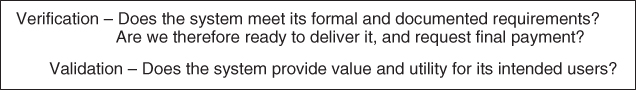
Figure 3.4 The two types of testing: verification and validation.
People sometimes like to poke fun at government regulations as being all useless “red tape,” so I am glad to be able to mention a bit of a US Government regulation that I consider profoundly insightful. In the US Government document called the Federal Acquisition Regulations,2 it says that a system may not be fielded until it has been demonstrated to be both effective and suitable.
The fact that it uses both of the terms effective and suitable implies that the writer thought that they were different, and therefore the possibility exists that a system could be effective without being suitable, or suitable without being effective.
In the usage that I advocate, effective means that the system meets the formal requirements contained in its specifications. This is an objective assessment that all mandatory requirements have been successfully implemented, and is proven through an appropriate verification program.
In the usage that I advocate, suitable means that the system is appropriate for its intended purpose, and for its intended users. This is inherently an assessment with some subjective aspects. Do the users like it? Does it fit the operational context for which it is intended (e.g. the confusion and stress of combat, of a nuclear power plant control room, of responding to a fire or a crime, and so forth)? Can it be operated by the intended personnel (e.g. does it require a Ph.D. in computer science in order to make full use of the system, when the intended operators of the system have 10th‐grade educations)? And so forth. Suitability is demonstrated through the validation activity; since suitability usually has a significant subjective aspect, a validation activity is quite different from a verification activity (which is objective, in the sense that verification checks off one requirement after another, until all requirements are checked off).
In principle, one could argue that since we took the trouble to understand the users, their value system, their needs, and their desires before we wrote the requirements, all of these suitability factors ought in fact to be incorporated into the formal requirements, and verifying those formal requirements will automatically ensure that the system is suitable, as well as effective. I have seen, unfortunately, many instances where a system meets all of its formal requirements, and the users still dislike the system – and at times, have even refused to use the system. This is not a good outcome for your project!
How does this occur? In my experience, it is simply difficult to capture all of the factors that relate to suitability in the formal requirements, and therefore conducting only verification does not always lead to satisfied users and stakeholders. Therefore, conducting both verification (which checks if the system is effective) and validation (which checks if the system is suitable) is good practice.
In summary:
- Verification determines if the system is effective. Verification is essentially an objective process.
- Validation determines if the system is suitable. Validation is usually a process with a significant subjective component.
Verification and validation are complementary processes; you generally need both.
Note that not everyone uses these terms – verification and validation – exactly this way, so be sure to check the definitions used on your project. If you are working in the aerospace industry, or building systems for a US Federal Government agency, what I described is likely exactly what they expect. Commercial contracts sometimes use the terms differently.
Let's define verification and validation in a little more detail. System verification is a set of actions used to check the correctness of any system, or portion of a system, where correctness in this context means it satisfies the written requirements. The verification process consists of the following steps:
- The items to be verified are every mandatory requirement in the entire project's specification tree (e.g. every sentence that contains the verb shall). Define a verification action for each mandatory requirement in the specification tree – that is, what will we inspect, measure, execute, or simulate? How will we do it? What portion(s) of our system will be involved? (We can often perform some parts of verification using only a portion of our entire system) What tools, recording mechanisms, and data will be involved? What types of personnel and expertise will we need? How many times will we need to do it? (If we have a requirement that is expressed statistically – and this is very common – we will need to collect a statistically valid set of samples.) And so forth.
- Define the expected result for each verification action, and define pass–fail criteria for each verification action. That is, when we perform the verification action, what result do we expect? What range of results will constitute a pass? What range of results will constitute a fail?
- Create a procedure (that is, a step‐by‐step checklist and methodology) for executing the verification actions, with all of the associated supporting artifacts: test tools, recording devices, input data, and so forth.
- Execute the procedures, obtaining and recording/logging the results.
- Determine which requirements pass, based on an objective assessment of whether they satisfied the pass–fail criteria assigned to that requirement.
Verification does not occur solely at the end of the project. Planning for verification takes place during earlier project phases, generally in parallel with the definition of the requirements and the realization of the design. The actual verification activity can take place at various times and levels of the hierarchy too. We will talk more about this aspect in a moment.
In contrast, system validation is a set of actions used to check the appropriateness of any system against its purposes, functions, and users. The validation process consists of the following steps:
- Create a list of items to be validated. These usually include each major system thread and each major system operation (as described in the system concept‐of‐operations document).
- For each item to be validated, define a validation action – that is, what will we inspect, measure, execute, or simulate? How will we do it? What portion(s) of our system will be involved? (For validation, generally, the entire system is involved.) What tools, recording mechanisms, and data will be involved? What types of personnel and expertise will we need? How many times will we need to do it? And so forth.
- Define the user's goals and expectations for each validation action, and describe what you believe will constitute conformance [e.g. how do we demonstrate that the user's (and other stakeholders') needs will be met].
- Create a procedure (that is, a step‐by‐step checklist and methodology) for executing the validation actions, with all of the associated supporting artifacts: test tools, recording devices, input data, and so forth. Note, however, that below I advocate that many important validation activities take place without the use of a procedure.
- Perform the indicated validation actions, obtaining and recording/logging the results.
- Make a determination (which will be at least in part subjective) of whether each result constitutes a pass or a fail. This will likely require having some of your users and your other stakeholders participate in creating the list of items to be validated, the validation actions, the list of user goals and expectations, and having them participate in the actual validation activities (or at least witness them). Ideally, the users participate in each decision about whether a validation step has been passed or not.
In contrast to verification, the actual validation activity does in fact generally take place largely at the end of the project. Planning for validation, however, like planning for verification, takes place during earlier project phases, generally in parallel with the definition of the requirements and the concept of operations document.
Some limited validation processes might take place earlier (e.g. assessment of the human interfaces of the system), but these will generally be repeated in the context of the entire system at the end of the development cycle
Figure 3.5 provides a side‐by‐side comparison of verification and validation.
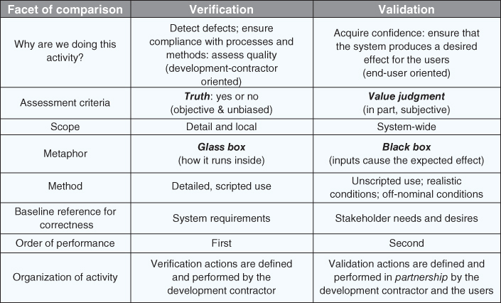
Figure 3.5 Comparison of verification and validation.
3.1.4 Testing – Planning, Procedures, Test Levels, Other Hints About Testing
During the requirements phase, we will not only define the requirements; recall how we said that we must also identify how we are going to test each requirement (we called this the test method). We do this in order to prevent accidently writing requirements that cannot be tested.
Hence, we select a test method for each requirement. Typically, these are one of the following:
- Inspection
- Demonstration
- Analysis
- Simulation
- Assessment via operation.
These terms are defined in Figure 3.6.
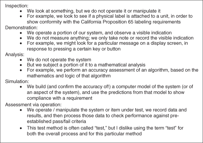
Figure 3.6 The principal test methods.
We capture this information in what is termed a test verification matrix. This is a fancy term for the simple idea of a two‐column chart, with the left‐hand column being the paragraph number of each requirement (recall that we give each separate requirement – indicated by use of the verb shall – its own unique paragraph number in the specifications, so each paragraph number identifies a unique requirement) and the right‐hand column being the name of one of the five test methods. See Figure 3.7 for an example.
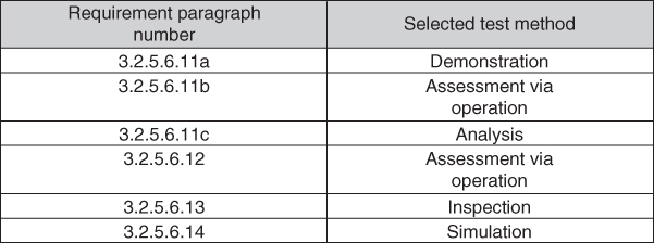
Figure 3.7 Example excerpt from a test verification matrix.
The test verification matrix usually becomes an appendix to each requirements specification document.
Having selected a test method for each requirement, we are ready to start planning our test program, and ready to create an important artifact called the test plan. Here's how to do that.
A typical system will have 1000 or more requirements … or 10 000. Usually, multiple requirements can be verified through a set of related actions. Doing so provides efficiency, and thereby reduces the cost of the test program.
So, we need to identify those groupings of requirements that can be verified through a set of related actions and arrange the test program to suit. My approach is as follows:
- Prepare the test verification matrix (e.g. select a test method for each requirement).
- Define test levels for each requirement (which I discuss below).
- Make a preliminary grouping of requirements into test cases (where each test case is a set of requirements that can be tested together, through a set of related actions).
- Define scenarios, test data, stimulators/drivers, instrumentation, analysis tools for each test case, and then look for similarities across the test cases. Use this information to improve the groupings of requirements into test cases.
- Develop the sequencing of the test cases and their interdependencies (perhaps one cannot start until another has completed, etc.).
- All of the above items together constitute the test plan.
In the above, I used the term test levels. Here's why we introduce this concept.
Like many other aspects of systems engineering, we use a hierarchy in our test program. Whereas in creating the requirements and design we traversed those hierarchies in a top‐down fashion, in testing, we will generally traverse that hierarchy in a bottom‐up direction (as indicated in the “U” diagram of Chapter 2).
What does it mean to test in a bottom‐up direction? It means that we first test small pieces, then small integrated assemblies, then larger integrated assemblies, and only then do we attempt to test the entire system. You will see that testing therefore is following an approach similar to that we defined above for integration.
We do this because it is easier and less expensive to test smaller pieces than big pieces (just like it was for integration) … and it turns out that some requirements can be completely tested and signed off as being formally verified at a level below the system level. This is possible because one can show that nothing that gets added/integrated later will perturb that verified performance. When it is possible to test something at a level below the system level, that's what you want to do; just as for integration, it is less expensive to test a requirement at a lower test level than at a higher one.
So, we must assign the test of each requirement not only to a test method (as described above) but also to a test level. In doing so, we identify:
- The lowest level in the hierarchy at which we can test each particular requirement.
- Which requirements can be tested once (at that low level) and which requirements might need to be tested at more than one level. We might do this because we believe that we can test a requirement at a given low test level, but there may be some uncertainty about whether interactions with other components will invalidate the results of those low‐level tests. In such a situation, we will test the requirement at the lower level (where it is easier and cheaper to find and fix the problems) and also include that requirement in a test case at a higher level of testing, so as to prove that no result from that lower‐level test was invalidated by the other components.
- The goal is always to test at the lowest level possible, because (as was the case for integration) it is easier to find and fix problems in small‐scale settings, and it costs less to find and fix each error in small‐scale settings.
You will recall that I mentioned during our discussion of the implementation stage that there are some basic features of each piece that we should check out right as we do the implementation. This is, as we can now see, simply an assignment of those particular features to the lowest of the test levels, that of a single piece of the implementation. In software, this lowest level is often called a unit, and this type of testing is therefore called unit testing.
We cannot select test levels until the design is complete, so we do not include the assignment of requirements to a test level in the requirements specification.
Once test planning is complete, once can turn one's attention to the preparation of test procedures. A test procedure is the detailed, step‐by‐step instructions for conducting each test. It must include all of the supporting tools and information needed to conduct the test, such as scenarios, data, configuration instructions, stimulators, and test drivers (if you are testing only a portion of your system, you might need some special tools to operate that portion by itself, to inject data into that portion, and to capture the outputs of that portion), and pass–fail criteria.
Test procedures can be big, complicated documents, and getting them right will usually require a significant number of practice runs (some people calls these dry‐runs); during and after each practice run, you can make corrections and improvements to the test procedure (a process we call red‐lining the test procedure).
One can often work out significant portions of your test procedures during the integration activity. But don't expect to get all of your test procedures to be sorted out during integration; the purposes of integration and testing are different!
The natural tendency is to hope that all goes well during your testing. But I have found that it is actually important to push your system past its nominal limits, and past the expected operating conditions; you want to make your system fail, so that you can find its boundaries of effective operation and (this next item is really important!) understand what happens when it is operated outside of those boundaries. Does it just slow down when overloaded, or does it actually lose valuable data? Does it slow down or shut off when overheated, or does it let the system actually sustain damage? You need to know these types of things, and at times you will decide to make changes to the design and implementation so that the system behaves better under such off‐nominal and beyond‐boundary conditions. Systems that pass their requirements but behave poorly when pushed to their limits are often rejected by users as “not suitable.” Don't let this happen to you!
The methods above test effectiveness (e.g. verification); we still need to test suitability (e.g. validation). The following summarizes the methods that I use for this purpose. Notice that they are quite different from the methods described above for verification:
- Unscripted use of the system
- Realistic operating conditions
- Off‐nominal operating conditions.
These are each described in the subsections below.
3.1.4.1 Unscripted Use of the System
You might be amazed at how often users find ways to use your system differently than you expected it to be employed. In fact, many systems are used for missions and capabilities other than those for which they were originally designed; think of a screwdriver being used as a chisel. In fact, there are billion‐dollar systems that are used only for a mission other than that for which they were originally designed; the users discovered something more valuable to do with the system, and decided to use it only for that more valuable mission. The US Air Force Airborne Warning and Control System (AWACS) is a good example of this; intended to manage air defense, during testing the users decided that the AWACS was fantastic to manage offensive air operations, and the system was repurposed for that mission.3
Such valuable insights can only be obtained by allowing the users to have unscripted access to use the system. During verification, only the carefully designed specific sequences contained in the test procedures are executed; no deviations at all from that script are permitted. During validation, we at times do the opposite: I have found it essential to allow the users unscripted access to use the system. That is, we train the users in the operation of the system, and then let them experiment with it, while watching and recording what they are doing. From such observations, we learn where the system seems to confuse them or slow them down; they learn what the system can do, and might invent new or additional uses, as described above for the AWACS.
Here is another example of such a repurposing of a system, based on insights learned during validation. I was project manager for an army system that was intended for use during close‐combat operations; however, during unscripted validation experiments, the users discovered that the system was in fact also valuable during maneuver, planning, and supply/support operations. Those roles were then incorporated into the contract as formal capabilities of the system, and in future versions we enhanced the capabilities of the system so as to be even more suitable for the users during those additional mission operations. Support for missions that originally were outside the scope of our contract became some of the main and most valued features of the system!
3.1.4.2 Realistic Operating Conditions
Many of the systems that we build are designed to support people in stressful or emergency conditions. Examples include police, fire, and ambulance dispatch and management; military systems; controls for nuclear power plants, oil refineries, chemical plants, and other complex industrial sites; and many others. In other cases, it might be the system that is under stress, rather than the operators: periods of very high input loads, periods of computational stress, periods that require exact timing or accuracy requirements, and so forth. Another common situation is teamwork: multiple people (perhaps at different locations) have to collaborate in order to accomplish a task. Most systems have opportunities for interruptions to a task in progress, and opportunities to multiplex operator attention between more than one task. Lastly, it might be the operating environment that is under stress, rather than the people or the system: electronic jamming, cyber attack, problems with electric power, and so forth.
It is unlikely that the verification activity is going to explore these sorts of situations in adequate detail. So, we do this type of exploration during validation. This requires different scenarios, and sometime additional stimulators/simulators, so as to create the loads and stresses.
3.1.4.3 Off‐Nominal Operating Conditions
Your system probably has a requirement to operate up to a specified maximum ambient temperature, and similarly down to a specified minimum ambient temperature. But what happens to your system if the temperature is 10 °F above the specified maximum? Do things catch on fire? Do things sustain permanent damage? Or is the effect more transitory, and the system will operate again according to its specifications when things cool down a bit?
There are many such off‐nominal conditions to explore: input data presented at a faster rate than allowed for in the specifications, more physical shock and/or vibration, under‐ and over‐voltage conditions on the power lines, recovery from power outages, incorrect actions by users, and so forth. You and your users need to understand how the system behaves under such circumstances.
Summary for testing
Usually, because they are so different, verification and validation are separate events. You must pass both verification and validation! You can learn from them both too.
The following are what I have found to be typical errors in the design of a test program:
- Not investing enough in scenarios, drivers/stimulators, instrumentation, and analysis tools. These are little development projects in themselves, and require schedule, budget, and appropriately skilled people.
- Not allowing enough time and money for the integration stage. Without a good integration phase, the chances of success during the test stage are significantly reduced.
- Not allowing enough time and money for a lot of refining and rewriting of test procedures. As noted above, your test procedures will need to be tried out (we use the term dry‐run); you will find things that are wrong, incomplete, or ambiguous; you will need to fix them, and then do another dry‐run. You will almost certainly do more iterations through this process – for every single test procedure – than you likely anticipate. Get data from previous projects to help you estimate the size of this activity.
- Not pushing your system until it breaks (e.g. what above was called using realistic operating conditions and off‐nominal operating conditions).
- Not investing enough in configuration control and a change control process. The test program is fast‐paced, and a lot of things happen at once. It is very easy in such a setting accidently to run a test using the wrong version of a piece of software, or use the wrong version of a data file, and so forth. You need good configuration control (e.g. the mechanism to ensure that a version of an article is the one you intend to use) and good change control (e.g. the mechanism you use to authorize and document the decision process about making changes to an article) in order to prevent making such errors.
We will examine – in a quantitative sense – how well testing works to remove defects later in Chapter 14. The short answer is “not as well as you would like.” This is primarily because most systems today have lots of software in them, and large software products are simply so complicated that they always have lots of latent defects. There is a very large range for the number of such latent defects, however: some systems have 20 times more defects per line of software code than other, similar systems. The techniques in this book will help you end up at the good end of those ranges.
3.1.5 Production
For some systems, you are only going to build one copy of the resulting system. For other systems, you might be under contract to build 10 copies; or 1000; or 100 000 000. Alternatively, the number to be produced may not be completely defined in advance; you will produce them until people stop buying them.
We call the project life‐cycle stage where we make these additional copies of our system production. The techniques for making these additional copies vary significantly depending on the scale of the planned production:
- If you are only going to build one item (e.g. a specialized satellite), you may be content to have your engineering staff do portions of the production and assembly.
- If you are going to build 10 (e.g. an entire constellation of a particular type of satellite), you may decide to hire some specialized production staff to build units 2 through 10, and stock a warehouse in advance with all of the necessary parts.
- If you are going to build 1000, you may invest in some automation to do some of the assembly: pick‐and‐place machines to build electronic circuit cards, for example. You will probably also have a production staff that is completely disjoint from your engineering staff.
- If you are going to build 1 000 000 (or 100 000 000), you will probably invest in a lot of automation to do the assembly: robots to do the work at each assembly station; machines to move items from one assembly station to another, and so forth. You will probably manage your parts differently too: instead of just amassing all of the parts you need in advance, you might establish a sophisticated supply chain to provide the parts you need on a just‐in‐time basis.
Why not use the best production techniques (robots, a complicated just‐in‐time supply chain, etc.) for every project? You will likely find that it is too expensive to set such mechanisms up for smaller production runs. We must therefore design our production processes based on an estimate of how many copies, over what period of time, we will be making of our system.
Another important decision about production is what your company will do themselves versus what you will buy from other companies. We call this a make/buy decision.
Companies used to aspire to do almost everything themselves, in their own facility; this approach provided a great deal of control. The Ford Motor Company was famous for a plant that it used to operate just west of Detroit, where they claimed that iron ore and raw rubber went in one end, and finished cars came out the other.
No one builds cars this way any longer; companies have found it too hard to be good at everything. This has led to a strategy of picking the things that you want your company to be good at, and buying other components from companies who you believe are good at that kind of work. Car companies, in fact, generally no longer even buy small parts; they buy large subassemblies (transmissions, front‐end chassis assemblies that already combine suspension, brakes, and steering, and so forth).
What this all means is that the design of our production process is part of our responsibilities, just like the design for the rest of our system!
Consider the following:
- There will be a big difference in up‐front versus recurring costs, depending on what you make versus what you buy. It requires more up‐front investment to make a part than to buy it, but the recurring cost may be lower. A big reason to select buy is that you can pass a lot of the risk (which we will discuss later in Chapter 9) and inventory cost to your supplier. You must balance all of these factors, and select make or buy for every part in your system.
- For those items that you elect to buy, for each you must decide whether you want to buy individual parts (e.g. shock absorbers and brake calipers) or complete subassemblies (e.g. entire integrated front‐end chassis assemblies).
- There will be a big difference in up‐front and recurring cost, depending on how you do the production, as described above. You must select a production approach that balances these two types of costs.
- Different designs will turn out to be easier or more difficult to produce in quantity; if your system is planned to have significant production, you must include producibility as a goal of your design process.
- There will also be a big variation in the defect rate induced by different assembly methods; generally, more automation (which, of course, costs money) results in lower assembly defect rates. You can also influence the defect rate significantly by a good design for the assembly process.
- Errors arise not just from defective parts (whether hardware or software), but also from defective assembly (e.g. parts inserted upside‐down, over‐tightened, wrong part in a particular location, wrong assembly sequence, missing or left out, and so forth). You can design the parts and the assembly sequence so as to minimize the likelihood of such errors.
- You must also design the assembly process to match the skills of your intended assembly personnel.
- You must account for these sources of error in your system reliability, availability, and mean‐time‐to‐repair predictions. These parameters are likely to be contractually binding, so satisfying them is not optional.
Since parts can be defective, and since the assembly process can introduce errors, we must do a small amount of testing on the items we produce. Sometimes, you conduct an abbreviated test (called subsequent‐article testing, because these are items produced subsequent to the first copy of the system) on every copy. In other circumstances, you may elect to test only some of them (e.g. every tenth item, etc.).
3.1.6 Deployment: Use in Actual Mission Operations
Let's consider a scenario where our project is building a satellite. It is complete, and sitting in our factory or test facility. It is not providing much value to the user at that location; it needs to be shipped to a launch site, mated with a launch rocket, launched into the correct orbit, checked out in orbit, and then connected to the ground station that will send it control signals and receive the product from the satellite's sensors. These latter steps are an example of a deployment activity, our next stage in the life‐cycle.
Let's consider another example, one where our project is building a new automation system for a large chain of hospitals, a system that will combine accounting, billing, insurance processing, patient case management, and electronic patient records. As you can see, our system is going to be both safety‐critical and very important to the hospital (and their patients). Our new system may not need to be launched into space, but the deployment stage is still quite complicated: we must disassemble the system in our factory, pack it, and ship the appropriate parts without damage to each of the various locations where they will be installed. We must physically and electronically install it, without disabling the existing systems that will continue to perform these same functions until our system is ready to take over. We must train the staff who will use the new system. We must do some sort of trial operations, so as to verify that our system works properly in the actual context of the hospital. All kinds of things can go wrong: for example, one of our computers may be located close to a medical machine that periodically emits large bursts of electromagnetic energy, which causes our computer to crash! We cannot go live – that is, transition our system into actual mission operations – until we are sure that we have worked out all of these types of problems; the hospital cannot be “down” for even a minute, as lives are on the line. We therefore probably have to operate our new system in parallel with the old systems for some period of time (by which we mean that both the old and our new system receive all data inputs and process them, but only the old system is used for actual hospital operations) – perhaps for several weeks, and then organize a switch‐over that does not leave the hospital without service for more than some agreed‐to period of time (which might be very short indeed!). We must make sure that we have transferred all of the data from the old system to the new system, and that we have done so without violating any privacy provisions of the law. We must somehow confirm that all of the data (such as patient records) have been transferred correctly to our new system.
As you can see from these examples, the deployment stage can be quite complicated.
The typical steps involved in deployment include:
- Packing, shipping, installation
- Check‐out at site
- Initial training of operators
- Load actual mission databases
- Interconnection with real interfaces
- Configuration management:
- Have we loaded the right software?
- Have we loaded the right data?
- Have we correctly configured all of the settings?
- … and so forth.
- Transition into operations (“go live”):
- Dry‐runs
- Operate in parallel with legacy system
- Then cut‐over
- Be prepared to roll‐back!
- Lots of rehearsal will be required
- Instrumentation and analysis tools are required – the problems are not always obvious.
Once our system is in actual use (e.g. we have completed a successful deployment), it can finally be used by the intended users, and bring them the benefits for which it was designed. But those users need support: someone has to create training materials for the new system, and perhaps even conduct actual training classes. Things break, and someone has to diagnose and fix them. To effect those repairs, we will need replacement parts; we need someone to make those replacement parts. It is likely that we will continue to find errors in the system – even after the test program has completed – and we will need to fix those errors. Most systems are operated for a long time, and our users expect us to design and implement improvements to the system over the course of time that the system is operated. There are many other, related aspects of supporting our new system in effective operations; these are discussed in the next two life‐cycle phases.
3.1.7 Non‐project Life‐Cycle Stages
The remaining life‐cycle stages are usually not a project (following the definition of a project that we introduced in Chapter 1), but your project must create the ingredients of success for these stages too, even if someone else then receives responsibility for executing these stages.
3.1.7.1 Logistics
Typically, 80% of the cost of ownership of a system takes place after deployment. That's right; the entire cost of designing, building, and testing our system probably accounts for only 20% of the cost of operating the system for its full intended operating life.
Because of this, designing our system so that we minimize overall cost over the entire time period for which the system will be used (called the life‐cycle cost) is usually very important to our customers.
Furthermore, it is not always obvious what is actually going to incur the biggest portion of those life‐cycle costs. Consider a data center: a building full of computers, disks, and communications equipment. Perhaps this data center is going to be used for 20 years. Over those 20 years, what will likely cost the most? It might seem that the information technology (IT) equipment – those computers, disks, and communications gear – is likely to be the most expensive. But take a look at Figure 3.8, which graphically depicts a notional view of the relative magnitude of the life‐cycle costs over that 20‐year period.
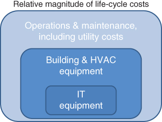
Figure 3.8 Notional relative magnitude of life‐cycle costs for a data center.
In the figure, you can see the small box that represents the cost of the information technology equipment. The next larger box represents the cost of the building and the heating/ventilation/air‐conditioning (HVAC) equipment; over the 20‐year life‐cycle, those items likely cost more than the computers and disks!
But the box representing the building and the HVAC is not the biggest box in the figure; the biggest box is the one that represents maintenance and utility costs. Most of this box is just paying for the electricity to run the data center! For many data centers, electricity is the dominant cost over the 20‐year life‐cycle.4
What does this mean to us? It means that, as designers, we ought to think about items such as:
- The power efficiency of the IT equipment: are there computers and disk drives that use a lot less power than others?
- The power efficiency of the HVAC: is there some type of air‐cooling method that uses a lot less power than other types?
- Are there investments we ought to make in power management controls for the computers and disk drives?
- The location where we place the data center may be more important than we think: a cold location could allow the use of ambient air as part of the cooling strategy (which might save a lot of electricity) versus a sunny site that might allow for the use of solar panels to generate the electricity needed to power the air conditioning.
Life‐cycle costs are a major design driver … in fact, often the major design driver.
Therefore, even though the post‐deployment activities are not usually part of our project, I will describe what takes place during those life‐cycle stages so that you understand the design objectives that arise.
What happens after we deploy our system? Activities such as the following:
- Operation of the system for its intended purpose by the users
- Sustainment
- Spares
- Training
- Support to operations
- Data‐gathering and record‐keeping.
I will describe each.
Operation of the System for its Intended Purpose by the Users
Trained personnel are assigned to operate the system. The intended missions are performed. Some process and people are assigned to monitor operations, manage the assignment of personnel, and look for problems with the system. Problems found generally fall into one of three categories: something might have broken; some consumable item might have run short; or some latent defect that was not uncovered and corrected during the test stage might have been encountered. The development contractor (us!) likely has a role in monitoring, assessing, and correcting such problems, especially those in the third category.
Sustainment
The system must be kept in operation. The system likely has some preventative maintenance actions that have been identified by the development contractor; for example, the manufacturer of your car probably suggests that you change the oil at specified intervals of time or distance traveled. A team of people have been trained and assigned to perform these preventative maintenance actions, and provided with the necessary equipment and parts to do so. In addition, as noted above, problems will be encountered that are determined to be caused by something breaking, or some consumable item (e.g. toner in the computer printer) having run short. A team of people has been trained and assigned to perform these corrective maintenance actions when such problems arise. In both cases, someone has to make a decision about the balance between having lots of such maintenance personnel at every location 24 hours per day, with lots of spare parts and consumable items right on hand (which allows corrective actions to take place promptly, but costs money), or some less intense strategy of assigning personnel and parts to locations and work‐shifts. Both types of maintenance (preventative and corrective) are tied to metrics of system availability, reliability, and allowed down‐time, which are often contractually binding commitments by the development contractor; you must design the maintenance activities so as to meet the contractually binding quality commitments. You must also match the difficulty of the maintenance tasks to the skill levels of available personnel, and to the training provided to those personnel. You must develop concepts for managing repair turnaround times (no one likes to wait for repairs!), including what will be done on‐site versus at a maintenance station or depot located elsewhere, and what will be done by the customer's personnel versus what will be done by the manufacturer and their suppliers. You may have to develop concepts for formal record‐keeping about failures, the certification or qualifications of the person performing the repairs, and maintenance logs; in some systems, these records are necessary to obtain and keep special certifications like flight‐worthiness and safety certifications. You must decide what tools (e.g. on‐line diagnostics/prognostics, on‐line manuals, etc.) will be cost‐effective for this system; you can spend more on diagnostic and prognostic tools and likely decrease mean time to repair, but that costs money too.
For us as the development contractor, the focus of sustainment planning is not just figuring out how many spare parts to stock. Rather, it is the determination of the balance between inherent reliability and maintenance – how are we going to make this system be operationally suitable, given its intended use, the nature of the mission, and the nature of the operators. We can design the system to be inherently more reliable (and thereby need fewer repairs and fewer repair parts), but that costs money too.
We must also balance the above consideration against the life‐cycle cost of the system; that is, within the trade space of the ways to balance between inherent reliability and maintenance that are operationally suitable, which of them have the most advantageous cost profile?
The sustainment planning trade space therefore often includes:
- Inherent reliability – designs that have higher inherent reliability often have lower maintenance costs but higher acquisition costs. Which balance is right for this system and this customer?
- Which personnel can/should do which type of maintenance/repair actions? Which are performed at operational locations, and which are performed at various sorts of depots and repair facilities? For example, most of the military systems that I have built have a three‐level maintenance concept: (i) some repairs are performed in the field, (ii) some repairs are performed at a military repair facility, and (iii) some items are returned to the contractor's facility for repairs.
- Most systems have an operational life far longer than the anticipated lifetime of their parts. How do we accommodate that? How do we deal with parts that become obsolete and/or unavailable? More flexible designs are possible, but usually have higher development costs.
- The system will experience errors and failures. What level of system capability must we continue to provide? How much of that is accomplished through design features, and how much is accomplished through diagnosis/repair/sparing strategies?
- Increasingly, software, rather than hardware, is what drives system reliability rates; how are we going to account for that during our design and test activities?
- Mean‐time‐to‐repair and mean‐time‐between‐failure, which combine to drive system availability, are often tradable with each other, and are each driven by design and maintenance plan decisions. What values do we choose for target mean‐time‐to‐repair, mean‐time‐between‐failure, and other related parameters?
Spare Parts
Repairs, of course, cannot be effected without spare parts. It is nice to have lots of spare parts right at hand, but having such a large inventory of spare parts costs money too. So, you must develop a strategy for spare parts: where are they kept (at the user's site, at a customer depot, at the factory, or some combination)? Furthermore, your system may be in service for years (even decades), but it is likely that at some point, the manufacturer of a part will stop making . Do you build up a big supply before that part is discontinued? Or do you redesign a portion of your system to make use of a newer part? You will also need an inventory control system to keep track of parts, where they are located, what is ordered, and when it will arrive, and to help you make predictions about when you need to order more parts.
Training
We have mentioned training of users, repair technicians, and others many times already. But people come and go, they retire, they move to another organization, they move to a different assignment within the same organization, they get promoted, etc. So, we must be training people all of the time! We must therefore predict and plan when we need to train people, how many people at which locations, select and qualify people to serve as the trainers, prepare training materials, and so forth. In some systems, we must keep formal records about who has received what training, as important personnel and system certifications may in part depend on records about people having completed periodic refresher training.
Support to Operations
All kinds of activity takes place behind the scenes of a large system. Upgrades, patches, and minor upgrades must be applied with minimal disruption to regular operations. Larger repairs and upgrades that require actual outages and down‐time must be scheduled and coordinated with the users. Training materials and documentation must be updated and corrected. If versions of the system are sold to users in other countries, materials need to be translated, culture differences need to be assessed and these effects incorporated in the systems operational concept, and so forth.
There is also an important opportunity for learning: the operation and use of the system can be observed by the development team, in order to create ideas for what improvements can be made to the system, and when those improvements should be made.
Data‐Gathering and Record‐Keeping
All of the above involves a great deal of data‐gathering and record‐keeping; we need good data in order to make good decisions. When should we order additional spare parts? How many parts should we keep at each operational site? How many maintenance personnel should we have on‐site at each location on each work shift? The number of questions that we must continually ask and answer during the post‐deployment stages is very large. We must always be ready to reassess; perhaps the load on the system has changed, or the relative cost of stocking parts in various locations has changed, or it is now cheaper just to throw away and replace a part rather than repair it. We make these decisions based on data. So, we must be gathering and analyzing data continuously, and keep well‐organized records.
Also, as noted above, sometimes our system and/or our system's operators require special certifications, and we must gather data and keep records to support those needs too.
3.1.7.2 Phase‐Out and Disposal
All good things come to an end, and eventually our system will be obsolete; or for some other reason, the users will be ready to retire it and remove it from service. We call this the phase‐out and disposal stage of our life‐cycle.
This stage can be difficult and complicated. For example, the system might include radioactive materials (even smoke detectors have radioactive materials in them, and must be properly disposed of). Or there might be other materials that require specialized disposal; for example, the lithium‐based batteries in most consumer electronics and computers.
Today's systems almost certainly contain data that cannot just be placed in a dump where others might get access to it. Properly erasing data is quite complicated, and is at times subject to laws and regulations about how it must be done; even the method of erasing a disk drive may be subject to law and regulation – just reformatting a disk drive is usually not enough.
This means that the phase‐out and disposal stage should be considered in the design as well. For example, it makes disposal easier, safer, and less expensive if those special materials can be easily removed from the system.
Lots of systems and devices require special disposal. Our systems can be designed to make this disposal easier. And don't forget about handling private data during disposal!
3.1.7.3 Summary for the Post‐Deployment Stages
Training and post‐deployment support are big drivers of user satisfaction (or dissatisfaction!). Resource these activities appropriately, and start working on your plans for how to accomplish them right at the beginning of the development program. All of the above activities need to be planned, budgeted, staffed, and monitored.
Remember, most of the costs of a system are incurred after deployment. We minimize and control those costs in large part through our design. So, even though the post‐deployment life‐cycle stages may not be a formal part of our project, we designers are the ones who determine whether the customer will be happy with the system after they start using it. We need to understand these post‐deployment life‐cycle stages because our design is an important factor in their success.
3.2 Next
We have devoted two chapters to discussing how we actually do engineering on projects. We will next use that knowledge to optimize our project management procedures in light of those engineering processes.
3.3 This Week's Facilitated Lab Session
This week is all lectures; there is no facilitated lab session.