AM and FM
Whether in analog or digital format, information has to be converted into radio waves before it can be sent. This process is known as modulation. It involves altering a radio wave of the desired frequency, called the carrier wave, so that a receiver will be able to extract useful information. There are two main types, familiar to all radio listeners: AM (amplitude modulation) and FM (frequency modulation).
Amplitude Modulation
The simplest way to transmit a signal is to superimpose it over the carrier wave at the transmitter. As illustrated in Figure 2.5, this results in waves with amplitude (height) that varies in proportion to the information signal.
AM is unusual in modern communications systems because it uses spectrum inefficiently compared to other methods. Many cycles of the carrier wave are needed to transmit a small amount of information, and the process of superposition creates extra signals in frequencies on either side of the carrier, known as sidebands. A variant of AM called SSB (single sideband), strips away these extra signals from one side, reducing the spectrum requirement by half.
The one application that still uses AM widely is broadcast radio. Several blocks of spectrum are dedicated to analog AM broadcasting in the long wave, medium wave, and shortwave bands, though the AM tuning dial on many radio receivers covers only medium wave. These AM bands usually carry only monophonic (as opposed to stereo) stations because of the limited capacity.
Figure 2.5. Amplitude modulation
Digital AM is also known as pulse modulation, because it is really just switching the carrier wave on and off to transmit short pulses. Its most important application is in fixed telephony: fixed networks also use radio waves, except that they're sent through a wire rather than through free space. Pulse modulation is also used for some satellite systems and has a revered history as the earliest type of radio. Up until around 1915, capacity was so restricted that all information had to be sent as Morse, an early code that used audible beeps. Radio listeners had to know how a series of beeps represented a letter of the alphabet, and had to transcribe messages manually. Many countries still require amateur radio broadcasters, known as hams, to pass tests in Morse.
Frequency Modulation
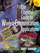
FM keeps the amplitude constant, meaning that a transmitter can operate at full power all the time to maximize its range. It instead alters the frequency (and the wavelength) of the carrier wave to represent variations in the signal being sent. Figure 2.6 shows a simple FM wave.
FM is more resistant than AM to noise. Both weather phenomena and machinery can produce random interference, which is more likely to affect the amplitude of a signal than its frequency. It can also use spectrum more efficiently, though the precise amount it needs depends on how much the signal is modulated. This is usually written mathematically. A radio station broadcasting at 92.8 MHz would typically vary the frequency by 100 kHz either side, so its frequency is written as 92.8 ± 0.1 MHz. Its total spectrum requirement is 200 kHz, so stations have to be spaced at least this distance apart to avoid interfering with each other.
Analog FM is most well-known through broadcasts in the VHF band, where it carries stereo radio stations. It's also used for TV and for many two-way radio systems, including first-generation cellphones.
Figure 2.6. Frequency modulated carrier wave
![]()
Phase Modulation
Digital wireless systems are usually based on phase modulation (PM), a special type of FM. Instead of just compressing and expanding waves, it rapidly moves them to a different point in their cycle. This is useful for transmitting data because the different points in a wave's cycle can represent bits.
The type of PM shown in 2.7 interrupts the wave very suddenly, a process known as PSK (phase-shift keying). The problem with this is that it requires a very large slice of spectrum because these sudden interruptions produce interference similar to AM sidebands. To minimize this and reduce the necessary spectrum, many systems use a technique called QAM (quadbit amplitude modulation), which adds some elements of AM. Others use D-PSK (differential PSK), which smooths out the interruptions by using phase differences rather than phase itself. The popular GSM standard uses yet another variant, GMSK (Gaussian minimum shift keying), a method which smooths the signal by passing it through various filters.
Phase modulation is particularly useful because it allows flexible bit rates. The two waves in Figure 2.7 interrupt their waves at equal intervals, but the lower one is carrying twice as much information as the other; it moves the wave to one of four different points on the cycle, rather than to just two. The different points in a cycle are known as symbols, and the number of interruptions per second as the symbol rate or baud.
A binary PM system, as at the top of Figure 2.7, uses only two points on a cycle, and so the bit rate is the same as the symbol rate. Quadrature PM, at the bottom of the diagram, represents four states and so can show two bits per symbol. Some technologies increase the number of bits per symbol when reception is clear, often to a maximum of 64. This provides six bits per symbol, effectively multiplying capacity by the same amount.
Figure 2.7. Phase modulation

Polarization
Transverse waves always vibrate at right angles to the direction of travel, which appears to be a single direction when they are drawn in two dimensions, as in the previous diagrams. But real space has (at least) three dimensions, giving the waves an entire plane in which to vibrate; if a wave was coming straight out of this page, it could be vibrating relative to the top or the sides of the page, or some angle in between. This angle is known as polarization, illustrated in Figure 2.8.
Though angles can vary infinitely, it's impossible to measure polarization to within more than two values: horizontal or vertical. These can be used to represent the two states of a bit, providing another way of encoding data into a light beam. Such polarization modulation is not used in present-day communications systems, but has been demonstrated in physics labs. It is proposed for various science fiction-like systems, including teleportation.
Some satellites already apply polarization, but as a means of increasing capacity rather than encoding data. Two beams polarized at right angles to each other do not produce interference, allowing the same frequency to be used twice. Mobile networks cannot do the same because polarization depends on the precise direction in which the transmitter and receiver are facing and requires a line of sight between them.
Figure 2.8. Horizontal and vertical polarization
