10
Oblique Wing Aircraft
One of the unspoken assumptions in aircraft design is that of bilateral or mirror symmetry. For slow flying vehicles this assumption appears to be fully justified. However, once the flight speed exceeds the velocity of sound, the laws of aerodynamics change in such a way as to make it seem inadvisable to arrange the components of an airplane side by side.
R.T. Jones [4]
Since the optimum optimum angle of sweep increases with the flight Mach number, a fixed‐wing aircraft has a considerable disadvantage. Hence, the swing wing concept features a wing with two panels having a variable sweep‐back angle, which increases with increasing Mach number. Several military supersonic aircraft with swing wings been operational and one of Boeing's early SST projects of the 1960s featured a swing wing (cf. Section 1.2).
An oblique wing – also known as a skewed or slewed wing – was originally proposed by E. de Marcay and E. Moonen in 1912, following the idea to vary the sweep of a wing for landing in side‐slip. It was further studied by R. Vogt in Germany for increasing the wing sweep as the speed of aircraft increases. In 1935 A. Busemann pointed out that an infinite swept wing in a supersonic flow is affected only by the flow component normal to the leading edge. In 1958 R.T. Jones noted that wave drag and vortex‐induced drag can be minimized by a variable‐sweep oblique wing with an elliptic lift distribution, as explained in Section 7.4.1, and he concluded that a wing of infinite extent could fly supersonically without the penalty of wave drag of the flight speed component so that its wing sweep angle becomes dependent of the flight Mach number.

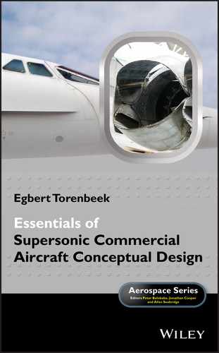
Figure 10.1 The Ames Dryden AD‐1 experimental aircraft. Courtesy: NASA.
10.1 Advantages of the Oblique Wing
Several conceptual designs of a second generation HSCT have featured an oblique wing as the most efficient concept to optimize the sweep angle for each flight speed. The following arguments, illustrated in Figures 10.1 and 10.2 are mostly used to support this opinion.

Figure 10.2 Geometric advantage of the oblique wing.
- The subsonic oblique wing demonstrator AD‐1 depicted in Figure 10.1 was intended to investigate the flying properties of an airplane with a pivoting oblique wing. By attaching the wing to the fuselage it can be turned to different angles so that flight at different Mach numbers can be made with high aerodynamic efficiency. For flight over land at speeds slow enough to avoid the sonic boom, the wing has a small sweep angle. For flight over water the sweep angle is increased dependent on the optimum Mach number in cruising flight.
- The oblique wing has a continuous structure with a pivot in the axial plane of symmetry to turn the wing over an angle dependent on the flight Mach number.
- Figure 10.2 illustrates that an oblique wing and a swept wing with the same area and span will have the same vortex‐induced drag, whereas the oblique wing will have a considerably lower wave drag due to lift. However, due to its bilateral asymmetry, this concept raises several complications for controlling the aircraft in flight.
Although the benefits of of a highly swept oblique wing were mainly found at transonic and higher speeds, it was recognized that flow compressibility did not have a major influence on many of the problems arising from asymmetry.
10.2 Practical Advantages of the Oblique Wing
The low‐cost, low‐speed, low technology AD‐1 made its first flight 1979 and successfully demonstrated the concept of a manned aircraft, sweeping the wing to a maximum of ![]() . However, the plane experienced cross coupling between the pitching moment and aileron deflection, contributing to unpleasant handling properties at sweep angles above
. However, the plane experienced cross coupling between the pitching moment and aileron deflection, contributing to unpleasant handling properties at sweep angles above ![]() . The oblique wing distributes the lift over twice the wing length compared to conventional, symmetrically swept wings. According to [22] this reduces the wave drag due to lift by a factor of four and the wave drag due to volume by a factor of sixteen.
. The oblique wing distributes the lift over twice the wing length compared to conventional, symmetrically swept wings. According to [22] this reduces the wave drag due to lift by a factor of four and the wave drag due to volume by a factor of sixteen.
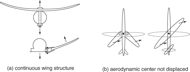
Figure 10.3 Advantages of the oblique wing for variable configurations.
Varying the sweep angle by turning the wing as a whole has several advantages over the swing wing concept. Turning the oblique wing with a single pivot has considerable practical advantages. Figure 10.3 illustrates the most essential of variable geometry, which demonstrates that the pivot of the obliquely swept continuous wing structure experiences no bending, whereas the swing wing arrangement has wing panels swept back at the wing root where the pivots are subject to high torque and bending loads. Also, sweeping the wing panels backwards for high‐speed flight displaces the center of pressure backwards, which compounds the normal rearward center of pressure shift with increasing speed. However, turning the wing of an OWB does not displace the centroid of area and hence the center of pressure relative to the center of gravity.
Figure 10.4(a) illustrates that the structure of the bilaterally symmetric wing with fixed geometry is less favorable because it experiences an unbalanced torsion at the wing root that must be counteracted by a bending moment on the fuselage structure. Moreover, the area rule works advantageously for a straight‐beam oblique wing in combination with a cylindrical fuselage body since a bilaterally symmetric wing requires a highly localized indentation resulting in a larger average fuselage body diameter, an impractical cabin layout and a heavier structure to contain the same number of passengers.

Figure 10.4 Advantages of the oblique wing for fixed geometry configurations.
10.3 Oblique Wing Transport Aircraft
An oblique wing and body combination (OWB) consists of a fuselage axially aligned with the direction of flight, a straight wing pivoted to the fuselage, fuselage‐mounted engines and lifting surfaces for stability and control. A typical example of a small OWB is depicted in Figure 10.5. Even though the range and fuel burn of the OWB airplane are not much different from that of a conventional configuration, its better low‐speed performance due to the wing's reduced yaw angle is attractive. And in addition to its capability to fly efficiently at subsonic speeds it is better suited for small noise‐sensitive or terrain‐challenged airports due to its short take‐off distance and steep climb capabilities. Being able to handle air traffic delays, holds and diversions to alternate airports better than a fixed‐wing airplane, it should also have more operational flexibility.

Figure 10.5 Example of a small supersonic oblique wing transport aircraft [12].
The OWB represents one of the simplest implementations of variable geometry and limiting the cruise speed to Mach 1.6 will permit the use of quiet low‐bypass turbofans allowing the oblique wing configuration to meet the demands for reducing noise levels around airports as well as the loudness caused by its sonic boom.
10.4 Oblique Flying Wing (OFW)
The unique oblique flying wing (OFW) configuration was first proposed in 1962 by Lee of Handley Page aircraft [2]. More recently, it was pioneered at Stanford University by Jones [9]. Figure 10.6 illustrates an early concept resulting from a Boeing in‐house assessment of the OFW. The OFW aircraft consists of a wing containing the payload and the fuel, whereas the engines and vertical tails are hinged to the wing so that their plane of symmetry stays in the flight direction. Dependent on the flight Mach number, the wing's yaw angle is variable during the flight up to (typically) ![]() so that the leading edge is swept behind the Mach cone. In this way the plane is enabled to reduce engine noise around airports as well as the sonic boom.
so that the leading edge is swept behind the Mach cone. In this way the plane is enabled to reduce engine noise around airports as well as the sonic boom.

Figure 10.6 Artist's concept of NASA's oblique flying wing.
When coupled with an aerodynamically optimal wing thickness ratio of approximately 12%, the wing is inherently able to preserve a straight (cylindrical) wing box, which allows for considerable gain in structural efficiency compared to conventional symmetric supersonic wings. To obtain a configuration having minimum drag at supersonic speeds it is necessary to specify the lift and volume within which the external dimensions must be limited. The favorable properties of the OFW requires that in high‐speed flight the wing has an angle of yaw such that the Mach number component normal to its long axis is subsonic.
The oblique wing arrangement distributes lift over about twice the length as a conventional swept wing of the same span and sweep, and with an elliptic distribution of the thickness and the chord along the span, its wave drag due to volume of the OFW is equal to that of the symmetrically swept wing having the same lateral span, whereas the vortex‐induced drag and the wave drag due to lift are both minimized. This provides a reduction in the wave drag due to volume by a factor of eight. Remarkably, the aerodynamic theory suggests that the straight wing of high aspect ratio which is ideal for low speed flight already has the right shape for the OFW at supersonic speeds.
10.4.1 OFW Flying Qualities and Disadvantages
The primary advantage of the OFW is its low aerodynamic drag at all flying speeds, resulting in excellent aerodynamic performance in subsonic, transonic, and supersonic flight up to ![]() . Due to its much larger length than the conventional arrow‐wing airplane the theoretical promise of minimum drag due to the increased longitudinal distribution of lift is very compelling, as are studies which have shown the potential for boom‐less flight at Mach numbers up to Mach 1.2. The really significant advantage of the OFW lies in the ease with which the sweep angle can be varied to suit flight conditions. The wing should be non‐swept during take‐off, landing or holding, and in cruising flight the aerodynamic efficiency may be up to
. Due to its much larger length than the conventional arrow‐wing airplane the theoretical promise of minimum drag due to the increased longitudinal distribution of lift is very compelling, as are studies which have shown the potential for boom‐less flight at Mach numbers up to Mach 1.2. The really significant advantage of the OFW lies in the ease with which the sweep angle can be varied to suit flight conditions. The wing should be non‐swept during take‐off, landing or holding, and in cruising flight the aerodynamic efficiency may be up to ![]() , which could lead to a very low engine thrust requirement. This configuration will thus minimize the drag in cruising flight as well as the unwanted display of energy in the airport environment. While unusual control effects can be prominent in rapid maneuvers, they are not noticeable when controls to maintain steady flight are activated and lack of bilateral symmetry of the HSCT configuration may not be important for cruising flight at high altitude. As a result, the engine integration effort results in lower installed engine cruise thrust and the OFW pays no range penalty for cruising at subsonic speeds. Hence, the range capability of the OFW aircraft depicted in Figure 10.7 may increase by up to 2,000 km if half of the original design mission is flown at Mach 0.95. However, considerable disadvantages of the OFW are the non‐ideal shape of the pressure cabin structure required for pressurization and the need for artificial stabilization.
, which could lead to a very low engine thrust requirement. This configuration will thus minimize the drag in cruising flight as well as the unwanted display of energy in the airport environment. While unusual control effects can be prominent in rapid maneuvers, they are not noticeable when controls to maintain steady flight are activated and lack of bilateral symmetry of the HSCT configuration may not be important for cruising flight at high altitude. As a result, the engine integration effort results in lower installed engine cruise thrust and the OFW pays no range penalty for cruising at subsonic speeds. Hence, the range capability of the OFW aircraft depicted in Figure 10.7 may increase by up to 2,000 km if half of the original design mission is flown at Mach 0.95. However, considerable disadvantages of the OFW are the non‐ideal shape of the pressure cabin structure required for pressurization and the need for artificial stabilization.

Figure 10.7 Airbus OFW design for a 250 passenger Mach 1.60 transport [19].

Figure 10.8 Geometry of an arrow‐wing HSCT configuration designed to carry 250 passengers over a distance of 10,000 km, cruising at Mach 1.60. [20].
10.5 Conventional and OWB Configurations Compared
Although the OWB configuration does not suffer from the OFW's complications, its aerodynamic efficiency is considerably lower than that of an OFW. The last section of this chapter will therefore be used to compare the aerodynamic efficiency of an oblique wing‐body configuration with a second generation HSCT with top level requirements described in Chapter 2. The configuration depicted in Figure 10.8 is designed according to the conventional approach, featuring an arrow wing with a fairly low notch ratio. It is expected to achieve ![]() in cruising flight – a significantly higher value than Concorde's aerodynamic efficiency. The traditional configuration HSCT will be compared with an OWB configuration designed according to the principles described in Section 10.3. Depicted in Figure 10.9, the design illustrates that the the OWB configuration can do considerably better than just improving the aerodynamic efficiency, based on the following characteristics:
in cruising flight – a significantly higher value than Concorde's aerodynamic efficiency. The traditional configuration HSCT will be compared with an OWB configuration designed according to the principles described in Section 10.3. Depicted in Figure 10.9, the design illustrates that the the OWB configuration can do considerably better than just improving the aerodynamic efficiency, based on the following characteristics:
- An essential difference between the conventional and the oblique‐wing configurations is the different wing span in the low speed condition. Comparison of Figures 10.8 and 10.9 shows that the OBW wing span is about 40% larger than that of the arrow‐wing HSCT. Since the required take‐off thrust for a specified take‐off field length [3], the AUW and take‐off lift coefficient are inversely proportional to the wing span. Hence the OWB needs only three engines instead of four, resulting in a considerably simpler and less expensive installed power plant.
- Both aircraft are assumed to have the same MTOW and cruise altitude. Although the MTOW of the OBW is expected to be considerably less than that of the HSCT, this advantage is not taken into account.

Figure 10.9 Proposed OWB transport aircraft depicted on the airfield.

Figure 10.10 The oblique plane configuration in cruising flight.
10.5.1 Practical Side‐effects
It is often stated that an oblique wing configuration suffers from an aero‐elastic problem due to the upward bending of the forward wing section. In reality this appears to be a minor issue that can be easily coped with by applying a warped wing shape, stiffened structure and/or ailerons on the outer wing half. Moreover, flight tests of the AD‐1 have proven that the inherent directional instability of a subsonic oblique wing is easily counteracted, whereas in supersonic flight the effect is expected to be insignificant.

Figure 10.11 The oblique plane configuration in cruising and low‐speed flight.
10.6 Conclusion
The drag prediction of the OWB configuration in cruising flight depicted on Figure 10.8 results in the aerodynamic efficiency ![]() , corresponding to a maximum efficiency of
, corresponding to a maximum efficiency of ![]() for
for ![]() . This result happens to correspond with the initially assumed cruise altitude of 13,500 m. However, if the plane cruises near the tropopause the aerodynamic efficiency decreases to
. This result happens to correspond with the initially assumed cruise altitude of 13,500 m. However, if the plane cruises near the tropopause the aerodynamic efficiency decreases to ![]() , with the result that the cruise drag and the required installed thrust increases by 10%. However, the maximum efficiency in cruising flight is not necessarily the best figure of merit when important other aspects are taken into account such as the effects on the reduced installed thrust and block fuel consumption. The overall optimization of the design is a very complex subject that is outside the contents of this text and it is emphasized that the comparison between the HSCT and the OWB configurations is the first step of a design iteration that does not guarantee that this will be a converging process. Using Equation (3.11) leads to a confirmation that the initially assumed MTOW of 250,000 kg can be realized on the condition that the overall efficiency of the power plant amounts to at least
, with the result that the cruise drag and the required installed thrust increases by 10%. However, the maximum efficiency in cruising flight is not necessarily the best figure of merit when important other aspects are taken into account such as the effects on the reduced installed thrust and block fuel consumption. The overall optimization of the design is a very complex subject that is outside the contents of this text and it is emphasized that the comparison between the HSCT and the OWB configurations is the first step of a design iteration that does not guarantee that this will be a converging process. Using Equation (3.11) leads to a confirmation that the initially assumed MTOW of 250,000 kg can be realized on the condition that the overall efficiency of the power plant amounts to at least ![]() . Moreover, it is not unlikely that a cruise Mach number up to Mach 1.8 can be achieved with little increase of fuel consumption since a slightly increased lift coefficient has a minor effect on
. Moreover, it is not unlikely that a cruise Mach number up to Mach 1.8 can be achieved with little increase of fuel consumption since a slightly increased lift coefficient has a minor effect on ![]() .
.
The analysis carried out in this chapter proves that designing a second generation HSCT according to transport aircraft having the oblique‐wing variable geometry concept offers the opportunity to realize a future supersonic civil transport aircraft with a flight efficiency that is twice as high as that of the Concorde. It is the author's opinion that the oblique wing‐body configuration discussed in the present chapter does not suffer from the complexities observed in many failed projects such as those discussed in Chapter 1. Arguably, the OBW transport aircraft cruising at Mach 1.6 has hardly more complex structure and systems than present‐day high‐subsonic jetliners. The only complication introduced by the oblique wing concept is the installation of the pivoting mechanism and, different from the present high‐wing configuration, a low‐wing configuration is likely to have a less complicated and lighter pivoting mechanism.
The present analysis shows that the oblique wing configuration has the promise of efficiently cruising at high speed as well as transonic and subsonic speeds, combined with excellent operational capabilities for improving the effects on the environment compared to the presently existing air transport system.
Bibliography
- 1 Jones, R.T., and Cohen R.T. High Speed Wing Theory. Princeton, NJ: Princeton University Press; 1960.
- 2 G.H. Lee Comments on a paper by D. Kuchemann: Aircraft Shapes and their Aerodynamics. Adv. Aerodynamic Sci. 12:201–218; 1961. Sobieczky, H. (editor), New Design Concepts for High Speed Air Transport. Wien: Springer‐Verlag; 1997.
- 3 Torenbeek, E. Advanced Aircraft Design. Chichester: John Wiley and Sons Ltd; 2013.
- 4 Jones, R.T. Reduction of Wave Drag by Antisymmetric Arrangement of Wings and Bodies. AIAA J. 10(2):171–176; 1972.
- 5 Jones, R.T. New Design Goals and a New Shape for the SST. Astronautics Aeronautics. December, p. 66–70; 1972.
- 6 Jones, R.T., and Nisbet J. Transonic Transport Wings – Oblique or Swept? Astronautics Aeronautics. January; 1974.
- 7 Kulfan, R.M. High‐Transonic‐Speed Transport Aircraft Study. NASA CR‐2465, September; 1974.
- 8 Nelms, W.P. Applications of Oblique‐Wing Technology – An Overview. AIAA Paper 76‐943. September; 1976.
- 9 Jones, R.T. The Oblique Wing – Aircraft Design for Transonic and Low‐Supersonic Speeds. Acta Astronautica. Vol. 4, p. 99–109. Oxford: Pergamon Press; 1977.
- 10 McMurty, T.C., Sim A. and Andrews W. AD‐1 Oblique Wing Program. AIAA Paper 81‐2354, November; 1981.
- 11 Van der Velden, A.J.M., and Torenbeek E. Design of a Small Supersonic Oblique‐Wing Transport Aircraft. J.Aircraft 26 (3):193; 1989.
- 12 Van der Velden, A.J.M. The Aerodynamic Design of the Oblique Flying Wing Supersonic Transport. NASA Contractor Report 177529, May; 1990.
- 13 Galloway, T., Gelhausen P., Moore M. and Waters M. Oblique Wing Supersonic Transport Concepts. AIAA Paper 92‐4230, August; 1992.
- 14 Waters, M., Ardema M., Roberts C. and Kroo I.M. Structural an Aerodynamic Considerations for an Oblique All Wing Aircraft. AIAA Paper 92‐4220, August; 1992.
- 15 Nelson, C.P. Effects of Wing Planform on HSCT off‐design Aerodynamics. AIAA Paper‐92‐2629, June; 1992
- 16 Van der Velden, A.J.M. Multi‐Disciplinary SCT Design Optimization. AIAA Paper 93‐3931, August; 1993 Augustus 1993.
- 17 Pei Li, Seebass R. and Sobieczky H. The Oblique Flying Wing as the New Large Aircraft. ICAS‐96‐4.4.2; 1996. Available at: http://www.icas.org/ICAS_ARCHIVE/ICAS1996/ICAS-96-4.4.2.pdf
- 18 Rawdon, B.K. Oblique All‐Wing Airliner Sizing and Cabin Integration. AIAA Paper 1975‐568; 1997
- 19 Pei Li and Seebass R. Manual Aerodynamic Optimization of an Oblique Wing Supersonic Transport. J.Aircraft. 36(6):907; 1999.
- 20 Torenbeek, E., Jesse E. and Laban M. Conceptual Design and Analysis of a Mach 1.6 Airliner. AIAA Paper 2004‐4541; 2004.
- 21 Wintzer, M., Sturdza P. and Kroo I. Conceptual Design of Conventional and Oblique Wing Configurations for Small Supersonic Aircraft. AIAA Paper 2006‐930; 2006.
- 22 Hirschberg, M., Hart D.M. and Beutner T.J. A Summary of a Half‐Century of Oblique Wing Research. AIAA Paper 2007‐150; 2007