
![]()
Nunchuk-Mouse
This chapter’s project is about attaching the Nintendo Wii Nunchuk to the Raspberry Pi. The Nunchuk has two buttons; an X-Y joystick; and an X, Y, and Z accelerometer. The sensor data is communicated through the I2C bus. Let’s have some fun using a Nunchuk as a pointing device for the X Window System desktop.
Project Overview
The challenge before us breaks down into two overall categories:
- The I2C data communication details of the Nunchuk device
- Inserting the sensed data into the X Window System desktop event queue
Since you’ve mastered I2C communications in other parts of this book, we’ll focus more on the Nunchuk technical details. The remainder of the chapter looks at the Linux uinput API that will be used for the X-Windows interface. The final details cover a small but critical X-Windows configuration change, to bring about the Nunchuk-Mouse.
Nunchuk Features
The basic physical and data characteristics of the Nunchuk are listed in Table 3-1.50
Table 3-1. Nunchuk Controls and Data Characteristics

For application as a mouse, the C and Z buttons fill in for the left and right mouse buttons. The joystick is used to position the mouse cursor.
While the Nunchuk normally operates at a clock rate of 400 kHz, it works just fine at the Raspberry Pi’s 100 kHz I2C rate.
![]() Note I encourage you to experiment with the accelerometer.
Note I encourage you to experiment with the accelerometer.
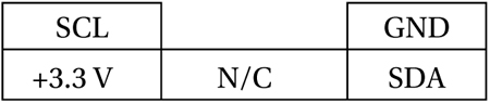
There are four wires, two of which are power and ground (some units may have two additional wires, one that connects to the shield and the other to the unused center pin). The remaining two wires are used for I2C communication (SDA and SCL). The connections looking into the cable-end connector are shown in Table 3-2.
Table 3-2. Nuncheck Cable Connections
The Nunchuk connector is annoyingly nonstandard. Some folks have rolled their own adapters using a double-sided PCB to mate with the inner connections. Others have purchased adapters for around $6. Cheap Nunchuk clones may be found on eBay for about half that price. With the growing number of clone adapters becoming available at more-competitive prices, there is less reason to cut off the connector.
![]() Tip Beware of Nunchuk forgeries and nonfunctional units.
Tip Beware of Nunchuk forgeries and nonfunctional units.
If you do cut off the connector, you will quickly discover that there is no standard wire color scheme. The only thing you can count on is that the pins are laid out as in Table 3-2. If you have a genuine Wii Nunchuk, the listed wire colors in Table 3-3 might be valid. The column labeled Clone Wire lists the wire colors of my own clone’s wires. Yours will likely differ.
Table 3-3. Nunchuk Connector Wiring

Before you cut that connector off your clone, consider that you’ll need to trace the connector to a wire color. Cut the cable, leaving about 3 inches of wire for the connector. Then you can cut the insulation off and trace the pins to a wire by using an ohmmeter (or by looking inside the cable-end connector).
Figure 3-1 shows the author’s clone Nunchuk with the connector cut off. In place of the connector, solid wire ends were soldered on and a piece of heat shrink applied over the solder joint. The solid wire ends are perfect for plugging into a prototyping breadboard.
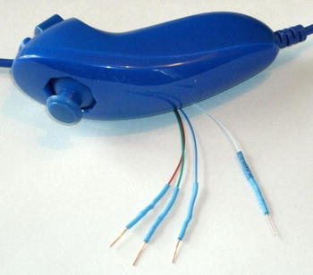
Figure 3-1. Nunchuk with wire ends
Testing the Connection
Once you’ve hooked up the Nunchuk to the Raspberry Pi, you’ll want to perform some simple tests to make sure it is working. The first step is to make sure your I2C drivers are loaded:
$ lsmod | grep i2c
i2c_bcm2708         3759         0
i2c_dev             5620         0
If you see these modules loaded, you’re good to go. Otherwise, manually load them now:
$ sudo modprobe i2c−bcm2708
$ sudo modprobe i2c−dev
Assuming the Raspberry Pi rev 2.0+, you’ll use I2C bus 1 (see Chapter 12 of Raspberry Pi Hardware Reference [Apress, 2014] if you’re not sure). Scan to see whether your Nunchuk is detected:
$ sudo i2cdetect −y 1
     0  1  2  3  4  5  6  7  8  9  a  b  c  d  e  f
00:          −− −− −− −− −− −− −− −− −− −− −− −− −−
10:  −− −− −− −− −− −− −− −− −− −− −− −− −− −− −− −−
20:  −− −− −− −− −− −− −− −− −− −− −− −− −− −− −− −−
30:  −− −− −− −− −− −− −− −− −− −− −− −− −− −− −− −−
40:  −− −− −− −− −− −− −− −− −− −− −− −− −− −− −− −−
50:  −− −− 52 −− −− −− −− −− −− −− −− −− −− −− −− −−
60:  −− −− −− −− −− −− −− −− −− −− −− −− −− −− −− −−
70:  −− −− −− −− −− −− −− −−
If the Nunchuk is working, it will show up in this display at address 0x52. With the hardware verified, it is time to move on to the software.
The Nunchuk contains a quirky little controller that communicates through the I2C bus. In order to know where to store bytes written to it, the first byte must be an 8-bit register address. In other words, each write to the Nunchuk requires the following:
- One register address byte, followed by
- Zero or more data bytes to be written to sequential locations
Thus for write operations, the first byte sent to the Nunchuk tells it where to start. Any following write bytes received are written with the register address incremented.
![]() Tip Don’t confuse the register address with the Nunchuk’s I2C address of 0x52.
Tip Don’t confuse the register address with the Nunchuk’s I2C address of 0x52.
It is possible to write the register address and then read bytes instead. This procedure specifies the starting location of data bytes to be read.
A quirky aspect of the Nunchuk controller is that there must be a short delay between writing the register address and reading the data. Performing the write followed by an immediate read does not work. Writing data immediately after the register address does succeed, however.
![]() Note The Nunchuk uses I2C address 0x52.
Note The Nunchuk uses I2C address 0x52.
Encryption
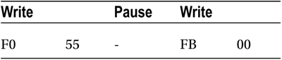
The Nunchuk is designed to provide an encrypted link. However, that can be disabled by initializing it a certain way.60 The defeat procedure is as follows:
- Write 0x55 to Nunchuk location 0xF0.
- Pause.
- Write 0x00 to Nunchuk location 0xFB.
The following illustrates the message sequence involved. Notice that this is performed as two separate I2C write operations:
Once this is successfully performed, all future data is returned unencrypted.
The whole point of the Nunchuk is to read its sensor data. When requested, it returns 6 bytes of data formatted as shown in Table 3-4.
Table 3-4. Nunchuk Data
Byte |
Bits |
Description |
|---|---|---|
1 |
Analog stick x axis value | |
|
2 |
Analog stick y axis value | |
|
3 |
X acceleration bits 9:2 | |
|
4 |
Y acceleration bits 9:2 | |
|
5 |
Z acceleration bits 9:2 | |
|
6 |
0 |
Z button pressed (active low) |
|
1 |
C button pressed (active low) | |
|
3:2 |
X acceleration bits 1:0 | |
|
5:4 |
Y acceleration bits 1:0 | |
|
7:6 |
Z acceleration bits 1:0 |
Some of the data is split over multiple bytes. For example, the X acceleration bits 9:2 are obtained from byte 3. The lowest 2 bits are found in byte 6, in bits 3 and 2. These together form the 9-bit X acceleration value.
To retrieve this data, we are always required to tell the Nunchuk where to begin. So the sequence always begins with a write of offset 0x00 followed by a pause:
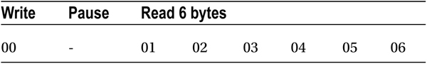
The Nunchuk doesn’t allow us to do this in one ioctl(2) call, using two I/O messages. A write of 0 must be followed by a pause. Then the 6 data bytes can be read as a separate I2C read operation. If the pause is too long, however, the Nunchuk controller seems to time out, resulting in incorrect data being returned. So we must do things the Nunchuk way.
While reading the Nunchuk is fun, we need to apply it to our desktop as a mouse. We need to insert mouse events based on what we read from it.
The Linux uinput driver allows programmers to develop nonstandard input drivers so that events can be injected into the input stream. This approach allows new input streams to be added without changing application code. Certainly the Nunchuk qualifies as a nonstandard input device!
A problem with this uinput API is its general lack of documentation. The best information available on the Internet seems to be from these three online sources:
- “Getting started with uinput: the user level input subsystem” http://thiemonge.org/getting-started-with-uinput
- “Using uinput driver in Linux- 2.6.x to send user input” http://www.einfochips.com/download/dash_jan_tip.pdf
- “Types” http://www.kernel.org/doc/Documentation/input/event-codes.txt
The only other source of information seems to be the device driver source code itself:
drivers/input/misc/uinput.c
The example program provided in this chapter can help pull all the necessary details together for you.
The header files required for the uinput API include the following:
#include <sys/ioctl.h>
#include <linux/input.h>
#include <linux/uinput.h>
To compile code, making use of I2C, you also need to install the libi2c development library, if you have not done that already:
$ sudo apt-get install libi2c-dev
The connection to the uinput device driver is made by opening the device node:
/dev/uinput
The following is an example of the required open(2) call:
int fd;

fd = open("/dev/uinput",O_WRONLY|O_NONBLOCK);
if ( fd < 0 ) {
    perror("Opening /dev/uinput");
    ...
Configuring Events
In order to inject events, the driver must be configured to accept them. Each call to ioctl(2) in the following code enables one class of events based on the argument event. The following is a generalized example:
int rc;
unsigned long event = EV_KEY;

rc = ioctl(fd,UI_SET_EVBIT,event);
assert(!rc);
The list of UI_SET_EVBIT event types is provided in Table 3-5. The most commonly needed event types are EV_SYN, EV_KEY, and EV_REL (or EV_ABS).
Table 3-5. List of uinput Event Types
|
Macro |
From Header File input.h53] Description | |
|---|---|---|
|
EV_SYN |
Event synchronization/separation | |
|
EV_KEY |
Key/button state changes | |
|
EV_REL |
Relative axis mouse-like changes | |
|
EV_ABS |
Absolute axis mouse-like changes | |
|
EV_MSC |
Miscellaneous events | |
|
EV_SW |
Binary (switch) state changes | |
|
EV_LED |
LED on/off changes | |
|
EV_SND |
Output to sound devices | |
|
EV_REP |
For use with autorepeating devices | |
|
EV_FF |
Force feedback commands to input device | |
|
EV_PWR |
Power button/switch event | |
|
EV_FF_STATUS |
Receive force feedback device status |
![]() Caution Do not or the event types together. The device driver expects each event type to be registered separately.
Caution Do not or the event types together. The device driver expects each event type to be registered separately.
Once you have registered your intention to provide EV_KEY events, you need to register all key codes that might be used. While this seems a nuisance, it does guard against garbage being injected by an errant program. The following code registers its intention to inject an Escape key code:
int rc;

rc = ioctl(fd,UI_SET_KEYBIT,KEY_ESC);
assert(!rc);
To configure all possible keys, a loop can be used. But do not register key code 0 (KEY_RESERVED) nor 255; the include file indicates that code 255 is reserved for the special needs of the AT keyboard driver.
int rc;
unsigned long key;

for ( key=1; key<255; ++key) {
    rc = ioctl(fd,UI_SET_KEYBIT,key);
    assert(!rc);
}
In addition to key codes, the same ioctl(2,UI_SET_KEYBIT) call is used to register mouse, joystick, and other kinds of button events. This includes touch events from trackpads, tablets, and touchscreens. The long list of button codes is defined in header file linux/input.h. The usual suspects are shown in Table 3-6.
Table 3-6. Key Event Macros
|
Macro |
Synonym |
Description |
|---|---|---|
|
BTN_LEFT |
BTN_MOUSE |
Left mouse button |
|
BTN_RIGHT |
Right mouse button | |
|
BTN_MIDDLE |
Middle mouse button | |
|
BTN_SIDE |
Side mouse button |
The following example shows the application’s intention to inject left and right mouse button events:
int rc;

rc = ioctl(fd,UI_SET_KEYBIT,BTN_LEFT);
assert(!rc);
rc = ioctl(fd,UI_SET_KEYBIT,BTN_RIGHT);
assert(!rc);
In order to inject EV_REL events, the types of relative movements must be registered in advance. The complete list of valid argument codes is shown in Table 3-7. The following example indicates an intention to inject x and y relative axis movements:
rc = ioctl(fd,UI_SET_RELBIT,REL_X);
assert(!rc);
rc = ioctl(fd,UI_SET_RELBIT,REL_Y);
assert(!rc);
Table 3-7. UI_SET_RELBIT Options
|
Macro |
Intention |
|---|---|
|
REL_X |
Send relative X changes |
|
REL_Y |
Send relative Y changes |
|
REL_Z |
Send relative Z changes |
|
REL_RX |
x-axis tilt |
|
REL_RY |
y- axis tilt |
|
REL_RZ |
z- axis tilt |
|
REL_HWHEEL |
Horizontal wheel change |
|
REL_DIAL |
Dial-turn change |
|
REL_WHEEL |
Wheel change |
|
REL_MISC |
Miscellaneous |
While we don’t use the EV_ABS option in this project, it may be useful to introduce this feature at this point. This event represents absolute cursor movements, and it too requires registration of intentions. The complete list of EV_ABS codes is defined in linux/input.h. The usual suspects are defined in Table 3-8.
Table 3-8. Absolute Cursor Movement Event Macros
|
Macro |
Description |
|---|---|
|
ABS_X |
Move X to this absolute X coordinate |
|
ABS_Y |
Move Y to this absolute Y coordinate |
The following is an example of registering intent for absolute x- and y-axis events:
int rc;

rc = ioctl(fd,UI_SET_ABSBIT,ABS_X);
assert(!rc);
rc = ioctl(fd,UI_SET_ABSBIT,ABS_X);
assert(!rc);
In addition to registering your intentions to inject these events, you need to define some coordinate parameters. The following is an example:
struct uinput_user_dev uinp;

uinp.absmin[ABS_X] = 0;
uinp.absmax[ABS_X] = 1023;

uinp.absfuzz[ABS_X] = 0;
uinp.absflat[ABS_X] = 0;

uinp.absmin[ABS_Y] = 0;
uinp.absmax[ABS_Y] = 767;

uinp.absfuzz[ABS_Y] = 0;
uinp.absflat[ABS_Y] = 0;
These values must be established as part of your ioctl(2,UI_DEV_CREATE) operation, which is described next.
Creating the Node
After all registrations with the uinput device driver have been completed, the final step is to create the uinput node. This will be used by the receiving application, in order to read injected events. This involves two programming steps:
- Write the struct uinput_user_dev information to the file descriptor with write(2).
- Perform an ioctl(2,UI_DEV_CREATE) to cause the uinput node to be created.
The first step involves populating the following structures:
struct input_id {
    __u16       bustype;
    __u16       vendor;
    __u16       product;
    __u16       version;
};

struct uinput_user_dev {
    char        name[UINPUT_MAX_NAME_SIZE];
    struct input_id id;
    int         ff_effects_max;
    int         absmax[ABS_CNT];
    int         absmin[ABS_CNT];
    int         absfuzz[ABS_CNT];
    int         absflat[ABS_CNT];
};
An example populating these structures is provided next. If you plan to inject EV_ABS events, you must also populate the abs members, mentioned in the “Configure EV_ABS” section.
       struct uinput_user_dev uinp;
       int rc;

       memset(&uinp,0,sizeof uinp);

       strncpy(uinp.name,"nunchuk",UINPUT_MAX_NAME_SIZE);

       uinp.id.bustype = BUS_USB;
       uinp.id.vendor = 0x1;
       uinp.id.product = 0x1;
       uinp.id.version = 1;

//     uinp.absmax[ABS_X] = 1023; /∗ EV_ABS only ∗/
//     ...

       rc = write(fd,&uinp,sizeof(uinp));
       assert(rc == sizeof(uinp));
The call to write(2) passes all of this important information to the uinput driver. Now all that remains is to request a device node to be created for application use:
int rc;

rc = ioctl(fd,UI_DEV_CREATE);
assert(!rc);
This step causes the uinput driver to make a device node appear in the pseudo directory /dev/input. An example is shown here:
$ ls –l /dev/input
total 0
drwxr−xr−x 2 root root     120 Dec 31  1969 by−id
drwxr−xr−x 2 root root     120 Dec 31  1969 by−path
crw−rw−−−T 1 root input 13, 64 Dec 31  1969 event0
crw−rw−−−T 1 root input 13, 65 Dec 31  1969 event1
crw−rw−−−T 1 root input 13, 66 Dec 31  1969 event2
crw−rw−−−T 1 root input 13, 67 Feb 23 13:40 event3
crw−rw−−−T 1 root input 13, 63 Dec 31  1969 mice
crw−rw−−−T 1 root input 13, 32 Dec 31  1969 mouse0
crw−rw−−−T 1 root input 13, 33 Feb 23 13:40 mouse1
The device /dev/input/event3 was the Nunchuck’s created uinput node, when the program was run.
The following code snippet shows how to post a key down event, followed by a key up event:
1 static void
2 uinput_postkey(int fd,unsigned key) {
3    struct input_event ev;
4    int rc;
5
6    memset(&ev,0,sizeof(ev));
7    ev.type = EV_KEY;
8    ev.code = key;
9    ev.value = 1;
10
11    rc = write(fd,&ev,sizeof(ev));
12    assert(rc == sizeof(ev));
13
14    ev.value = 0;
15    rc = write(fd,&ev,sizeof(ev));
16    assert(rc == sizeof(ev));
17 }
From this example, you see that each event is posted by writing a suitably initialized input_event structure. The example illustrates that the member named type was set to EV_KEY, code was set to the key code, and a keypress was indicated by setting the member value to 1 (line 9).
To inject a key up event, value is reset to 0 (line 14) and the structure is written again.
Mouse button events work the same way, except that you supply mouse button codes for the code member. For example:
memset(&ev,0,sizeof(ev));
ev.type = EV_KEY;
ev.code = BTN_RIGHT;        /∗ Right click ∗/
ev.value = 1;
Posting EV_REL Events
To post a relative mouse movement, we populate the input_event as a type EV_REL. The member code is set to the type of event (REL_X or REL_Y in this example), with the value for the relative movement established in the member value:
static void
uinput_movement(int fd,int x,inty) {
     struct input_event ev;
     int rc;

     memset(&ev,0,sizeof(ev));
     ev.type = EV_REL;
     ev.code = REL_X;
     ev.value = x;

     rc = write(fd,&ev,sizeof(ev));
     assert(rc == sizeof(ev));

     ev.code = REL_Y;
     ev.value = y;
     rc = write(fd,&ev,sizeof(ev));
     assert (rc == sizeof(ev));
}
Notice that the REL_X and REL_Y events are created separately. What if you want the receiving application to avoid acting on these separately? The EV_SYN event helps out in this regard (next).
The uinput driver postpones delivery of events until the EV_SYN event has been injected. The SYN_REPORT type of EV_SYN event causes the queued events to be flushed out and reported to the interested application. The following is an example:
static void
uinput_syn(int fd) {
    struct input_event ev;
    int rc;

    memset(&ev,0,sizeof(ev));
    ev.type = EV_SYN;
    ev.code = SYN_REPORT;
    ev.value = 0;
    rc = write(fd,&ev,sizeof(ev));
    assert(rc == sizeof(ev));
}
For a mouse relative movement event, for example, you can inject a REL_X and REL_Y, followed by a SYN_REPORT event to have them seen by the application as a group.
Closing uinput
There are two steps involved:
- Destruction of the /dev/input/event%d node
- Closing of the file descriptor
The following example shows both:
int rc;

rc = ioctl(fd,UI_DEV_DESTROY);
assert(!rc);
close(fd);
Closing the file descriptor implies the ioctl(2,UI_DEV_DESTROY) operation. The application has the option of destroying the device node while keeping the file descriptor open.
X-Window
The creation of our new uinput device node is useful only if our desktop system is listening to it. Raspbian Linux’s X-Windows system needs a little configuration help to notice our Frankenstein creation. The following definition can be added to the /usr/share/X11/xorg.config.d directory. Name the file 20-nunchuk.conf:
# Nunchuck event queue

Section "InputClass"
        Identifier "Raspberry Pi Nunchuk"
        Option "Mode" "Relative"
        MatchDevicePath "/dev/input/event3"
        Driver "evdev"
EndSection

# End 20−nunchuk.conf
This configuration change works only if your Nunchuk uinput device shows up as /dev/input/event3. If you have other specialized input device creations on your Raspberry Pi, it could well be event4 or some other number. See the upcoming section “Testing the Nunchuk” for troubleshooting information.
Restart your X-Windows server to have the configuration file noticed.
![]() Tip Normally, your Nunchuk program should be running already. But the X-Window server will notice it when the Nunchuk does start.
Tip Normally, your Nunchuk program should be running already. But the X-Window server will notice it when the Nunchuk does start.
When writing uinput event-based code, you will find the package input-utils to be extremely helpful. They can be installed from the command line as follows:
$ sudo apt−get install input−utils
The following commands are installed:
- lsinput(8): List uinput devices
- input-events(8): Dump selected uinput events
- input-kbd(8): Keyboard map display
This chapter uses the first two utilities: lsinput(8) and input-events(8).
Testing the Nunchuk
Now that the hardware, drivers, and software are ready, it is time to exercise the Nunchuk. Unfortunately, there is no direct way for applications to identify your created uinput node. When the Nunchuk program runs, the node may show up as /dev/input/event3 or some other numbered node if event3 already exists. If you wanted to start a Nunchuk driver as part of the Linux boot process, you need to create a script to edit the file with the actual device name. The affected X-Windows config file is as follows:
/usr/share/X11/xord.conf.d/20-nunchuk.conf
The script (shown next) determines which node the Nunchuk program created. The following is an example run, while the Nunchuk program was running:
$ ./findchuk
/dev/input/event3
When the node is not found, the findchuk script exits with a nonzero code and prints a message to stderr:
$ ./findchuk
Nunchuk uinput device not found.
$ echo $?
1
The findchuk script is shown here:
#!/bin/bash
######################################################################
# Find the Nunchuck
######################################################################
#
# This script locates the Nunchuk uinput device by searching the
# /sys/devices/virtual/input pseudo directory for names of the form:
# input[0_9]∗. For all subdirectories found, check the ./name pseudo
# file, which will contain "nunchuk". Then we derive the /dev path
# from a sibling entry named event[0_9]∗. That will tell use the
# /dev/input/event%d pathname, for the Nunchuk.

DIR=/sys/devices/virtual/input         # Top level directory
set_eu

cd "$DIR"
find . −type d −name 'input[0−9]∗' | (
      set −eu
      while read dirname ; do
              cd "$DIR/$dirname"
              if [−f "name"] ; then
                     set +e
                     name=$(cat name)
                     set −e
                     if [ $(cat name) = nunchuk] ; then
                            event="/dev/input/$ (ls−devent[0−9]∗)"
                            echo $event
                            exit 0            # Found it
                     fi
              fi
      done

      echo "Nunchuk uinput device not found." >&2
      exit 1
)

# End findchuk
Testing ./nunchuk
When you want to see what Nunchuk data is being received, you can add the -d command-line option:
$ ./nunchuk −d
Raw nunchuk data: [83] [83] [5C] [89] [A2] [63]
.stick_x = 0083 (131)
.stick_y = 0083 (131)
.accel_x = 0170 (368)
.accel_y = 0226 (550)
.accel_z = 0289 (649)
.z_button= 0
.c_button= 0
The first line reports the raw bytes of data that were received. The remainder of the lines report the data in its decoded form. While the raw data reports the button presses as active low, the Z and C buttons are reported as 1 in the decoded data. The value in the left column is in hexadecimal format, while the value in parenthesis is shown in decimal.
Utility lsinputs
When the Nunchuk program is running, you should be able to see the Nunchuk uinput device in the list:
$ lsinput
...
/dev/input/event2
   bustype   : BUS_USB
   vendor    : 0x45e
   product   : 0x40
   version   : 272
   name      : "Microsoft Micro soft 3−Button Mou"
   phys      : "usb−bcm2708_usb−1.3.4/input0"
   uniq      : ""
   bitsev    : EV_SYN EV_KEY EV_REL EV_MSC

/dev/input/event3
   bustype      : BUS_USB
   vendor       : 0x1
   product      : 0x1
   version      : 1
   name         : "nunchuk"
   bits ev      : EV_SYN EV_KEY EV_REL
In this example, the Nunchuk shows up as event3.
Utility input-events
When developing uinput-related code, the input-events utility is a great help. Here we run it for event3 (the argument 3 on the command line), where the Nunchuk mouse device is:
$ input−events 3
/dev/input/event3
   bustype   : BUS_USB
   vendor    : 0x1
   product   : 0x1
   version   : 1
   name      : "nunchuk"
   bits ev   : EV_SYN EV_KEY EV_REL

waiting for events
23:35:15.345105: EV_KEY BTN_LEFT (0x110) pressed
23:35:15.345190: EV_SYN code=0 value=0
23:35:15.517611: EV_KEY BTN_LEFT (0x110) released
23:35:15.517713: EV_SYN code=0 value=0
23:35:15.833640: EV_KEY BTN_RIGHT (0x111) pressed
23:35:15.833727: EV_SYN code=0 value=0
23:35:16.019363: EV_KEY BTN_RIGHT (0x111) released
23:35:16.019383: EV_SYN code=0 value=0
23:35:16.564129: EV_REL REL_X −1
23:35:16.564213: EV_REL REL_Y 1
23:35:16.564261: EV_SYN code=0 value=0
...
The Program
The code for nunchuk.c is presented on the following pages. The source code for timed_wait.c is shown in Chapter 1. We’ve covered the I2C I/O in other chapters. The only thing left to note is the difficulty of providing a smooth interface for events produced by the Nunchuk. Here are a few hints for the person who wants to experiment:
- If the mouse moves too quickly, one major factor is the timed delay used. The timed_wait() call in line 107 spaces out read events for the Nunchuk (currently 15 ms). This also lightens the load on the CPU. Reducing this time-out increases the number of Nunchuk reads and causes more uinput events to be injected. This speeds up the mouse pointer.
- The function curve() in line 349 attempts to provide a somewhat exponential movement response. Small joystick excursions should be slow and incremental. More-extreme movements will result in faster mouse movements.
- The Z button is interpreted as the left-click button, while the C button is the right-click button.
- No keystrokes are injected by this program, but it can be modified to do so. The function uinput_postkey() on line 244 can be used for that purpose.
1  /∗∗∗∗∗∗∗∗∗∗∗∗∗∗∗∗∗∗∗∗∗∗∗∗∗∗∗∗∗∗∗∗∗∗∗∗∗∗∗∗∗∗∗∗∗∗∗∗∗∗∗∗∗∗∗∗∗∗∗∗∗∗∗∗∗∗∗∗∗
2  ∗ nunchuk.c: Read events from nunchuck and stuff as mouse events
3  ∗∗∗∗∗∗∗∗∗∗∗∗∗∗∗∗∗∗∗∗∗∗∗∗∗∗∗∗∗∗∗∗∗∗∗∗∗∗∗∗∗∗∗∗∗∗∗∗∗∗∗∗∗∗∗∗∗∗∗∗∗∗∗∗∗∗∗∗∗/
4
5  #include <stdio.h>
6  #include <math.h>
7  #include <stdlib.h>
8  #include <fcntl.h>
9  #include <unistd.h>
10  #include <string.h>
11  #include <errno.h>
12  #include <signal.h>
13  #include <assert.h>
14  #include <sys/ioctl.h>
15  #include <linux/i2c−dev.h>
16  #include <linux/input.h>
17  #include <linux/uinput.h>
18
19  #include "timed_wait.c"
20
21  static int is_signaled = 0;      /∗ Exit program if signaled ∗/
22  static int i2c_fd = −1;          /∗ Open/dev/i2c−1 device ∗/
23  static int f_debug = 0;          /∗ True to print debug messages ∗/
24
25  typedef struct {
26          unsigned char stick_x;   /∗ Joystick X ∗/
27          unsigned char stick_y;   /∗ Joystick Y ∗/
28          unsigned accel_x;        /∗ Accel X ∗/
29          unsigned accel_y;        /∗ Accel Y ∗/
30          unsigned accel_z;        /∗ Accel Z ∗/
31          unsigned z_button:1;     /∗ Z button ∗/
32          unsigned c_button:1;     /∗ C button ∗/
33          unsigned char raw[6];    /∗ Raw received data ∗/
34 } nunchuk_t;
35
36  /∗
37  ∗ Open I2C bus and check capabilities:
38  ∗/
39  static void
40  i2c_init(const char ∗node) {
41           unsigned long i2c_funcs = 0;    /∗ Support flags ∗/
42           int rc;
43
44           i2c_fd = open(node,O_RDWR);     /∗ Open driver/dev/i2s−1 ∗/
45           if ( i2c_fd < 0 ) {
46                  perror("Opening/dev/i2s−1");
47                  puts("Check that the i2c−dev & i2c−bcm2708 kernel modules"
48                        "are loaded.");
49                  abort();
50          }
51
52           /∗
53            ∗ Make sure the driver supports plain I2C I/O:
54            ∗/
55           rc = ioctl(i2c_fd,I2C_FUNCS,&i2c_funcs);
56           assert(rc >= 0);
57           assert(i2c_funcs & I2C_FUNC_I2C);
58 }
59
60  /∗
61   ∗ Configure the nunchuk for no encryption:
62   ∗/
63  static void
64  nunchuk_init(void) {
65         static char init_msg1[] = {0xF0, 0x55};
66         static char init_msg2[] = {0xFB, 0x00};
67         struct i2c_rdwr_ioctl_data msgset;
68         struct i2c_msg iomsgs[1];
69         int rc;
70
71         iomsgs[0].addr = 0x52;     /∗ Address of Nunchuk ∗/
72         iomsgs[0].flags = 0;       /∗ Write ∗/
73         iomsgs[0].buf = init_msg1; /∗ Nunchuk 2 byte sequence ∗/
74         iomsgs[0].len = 2;         /∗ 2 bytes ∗/
75
76         msgset.msgs = iomsgs;
77         msgset.nmsgs = 1;
78
79         rc = ioctl(i2c_fd,I2C_RDWR,&msgset);
80         assert(rc == 1);
81
82         timed_wait(0,200,0);        /∗ Nunchuk needs time ∗/
83
84         iomsgs[0].addr = 0x52;     /∗ Address of Nunchuk ∗/
85         iomsgs[0].flags = 0;       /∗ Write ∗/
86         iomsgs[0].buf = init_msg2; /∗ Nunchuk 2 byte sequence ∗/
87         iomsgs[0].len = 2;         /∗ 2 bytes ∗/
88
89         msgset.msgs = iomsgs;
90         msgset.nmsgs = 1;
91
92         rc = ioctl(i2c_fd,I2C_RDWR,&msgset);
93         assert(rc == 1);
94 }
95
96  /∗
97   ∗ Read nunchuk data :
98   ∗/
99  static int
100 nunchuk_read(nunchuk_t ∗data) {
101         struct i2c_rdwr_ioctl_data msgset;
102         struct i2c_msg iomsgs[1];
103         char zero[1] = {0x00};    /∗ Written byte ∗/
104         unsigned t;
105         int rc;
106
107         timed_wait(0,15000,0);
108
109         /∗
110          ∗ Write the nunchuk register address of 0x00:
111          ∗/
112         iomsgs[0].addr = 0x52;    /∗ Nunchuk address ∗/
113         iomsgs[0].flags = 0;      /∗ Write ∗/
114         iomsgs[0].buf = zero;     /∗ Sending buf ∗/
115         iomsgs[0].len = 1;        /∗ 1 byte ∗/
116
117         msgset.msgs = iomsgs;
118         msgset.nmsgs = 1;
119
120         rc = ioctl(i2c_fd,I2C_RDWR,&msgset);
121         if ( rc < 0 )
122                return −1;         /∗ I /O error ∗/
123
124         timed_wait(0,200,0);      /∗ Zzzz, nunchuk needs time ∗/
125
126         /∗
127          ∗ Read 6 bytes starting at 0x00:
128          ∗/
129         iomsgs[0].addr = 0x52;             /∗ Nunchuk address ∗/
130         iomsgs[0].flags = I2C_M_RD;        /∗ Read ∗/
131         iomsgs[0].buf = (char ∗)data−>raw; /∗ Receive raw bytes here ∗/
132         iomsgs[0].len = 6;                 /∗ 6 bytes ∗/
133
134         msgset.msgs = iomsgs;
135         msgset.nmsgs = 1;
136
137         rc = ioctl(i2c_fd,I2C_RDWR,&msgset);
138         if ( rc < 0 )
139                return −1;        /∗ Failed ∗/
140
141         data−>stick_x = data−>raw[0];
142         data−>stick_y = data−>raw[1];
143         data−>accel_x = data−>raw[2] << 2;
144         data−>accel_y = data−>raw[3] << 2;
145         data−>accel_z = data−>raw[4] << 2;
146
147         t = data−>raw[5];
148         data−>z_button = t & 1 ? 0 : 1;
149         data−>c_button = t & 2 ? 0 : 1;
150         t >>= 2;
151         data−>accel_x |= t & 3;
152         t >>= 2;
153         data−>accel_y |= t & 3;
154         t >>= 2;
155         data−>accel_z |= t & 3;
156         return 0;
157 }
158
159 /∗
160  ∗ Dump the nunchuk data:
161  ∗/
162 static void
163 dump_data(nunchuk_t ∗data) {
164         int x;
165
166         printf("Raw nunchuk data : ");
167         for ( x=0; x<6; ++x)
168                printf("[%02X]",data−>raw[x]);
169         putchar('
'),
170
171         printf(".stick_x = %04X (%4u)
",data−>stick_x,data−>stick_x);
172         printf(".stick_y = %04X (%4u)
",data−>stick_y,data−>stick_y);
173         printf(".accel_x = %04X (%4u)
",data−>accel_x,data−>accel_x);
174         printf(".accel_y = %04X (%4u)
",data−>accel_y,data−>accel_y);
175         printf(".accel_z = %04X (%4u)
",data−>accel_z,data−>accel_z);
176         printf(".z_button= %d
",data−>z_button);
177         printf(".c_button= %d

",data−>c_button);
178 }
179
180 /∗
181  ∗ Close the I2C driver :
182  ∗/
183 static void
184 i2c_close(void) {
185           close(i2c_fd);
186           i2c_fd = −1;
187 }
188
189 /∗
190  ∗ Open a uinput node :
191  ∗/
192 static int
193 uinput_open(void) {
194         int fd;
195         struct uinput_user_dev uinp;
196         int rc;
197
198         fd = open("/dev/uinput",O_WRONLY|O_NONBLOCK);
199         if ( fd < 0 ) {
200                perror("Opening/dev/uinput");
201                exit(1);
202          }
203
204         rc = ioctl(fd,UI_SET_EVBIT,EV_KEY);
205         assert(!rc);
206         rc = ioctl(fd,UI_SET_EVBIT,EV_REL);
207         assert(!rc);
208
209         rc = ioctl(fd,UI_SET_RELBIT,REL_X);
210         assert(!rc);
211         rc = ioctl(fd,UI_SET_RELBIT,REL_Y);
212         assert(!rc);
213
214         rc = ioctl(fd,UI_SET_KEYBIT,KEY_ESC);
215         assert(!rc);
216
217         ioctl(fd,UI_SET_KEYBIT,BTN_MOUSE);
218         ioctl(fd,UI_SET_KEYBIT,BTN_TOUCH);
219         ioctl(fd,UI_SET_KEYBIT,BTN_MOUSE);
220         ioctl(fd,UI_SET_KEYBIT,BTN_LEFT);
221         ioctl(fd,UI_SET_KEYBIT,BTN_MIDDLE);
222         ioctl(fd,UI_SET_KEYBIT,BTN_RIGHT);
223
224         memset(&uinp,0,sizeof uinp);
225         strncpy(uinp.name,"nunchuk",UINPUT_MAX_NAME_SIZE);
226         uinp.id.bustype = BUS_USB;
227         uinp.id.vendor = 0x1;
228         uinp.id.product = 0x1;
229         uinp.id.version = 1;
230
231         rc = write(fd,&uinp,sizeof(uinp));
232         assert(rc == sizeof(uinp));
233
234         rc = ioctl(fd,UI_DEV_CREATE);
235         assert(!rc);
236         return fd;
237 }
238
239 /∗
240  ∗ Post keystroke down and keystroke up events:
241  ∗ (unused here but available for your own experiments)
242  ∗/
243 static void
244 uinput_postkey(int fd,unsigned key) {
245         struct input_event ev;
246         int rc;
247
248         memset(&ev,0,sizeof(ev));
249         ev.type = EV_KEY;
250         ev.code = key;
251         ev.value = 1;            /∗ Key down ∗/
252
253         rc = write(fd,&ev,sizeof(ev));
254         assert(rc == sizeof(ev));
255
256         ev.value = 0;            /∗ Key up ∗/
257         rc = write(fd,&ev,sizeof(ev));
258         assert(rc == sizeof(ev));
259 }
260
261 /∗
262  ∗ Post a synchronization point :
263  ∗/
264 static void
265 uinput_syn(int fd) {
266         struct input_event ev;
267         int rc;
268
269         memset(&ev,0,sizeof(ev));
270         ev.type = EV_SYN;
271         ev.code = SYN_REPORT;
272         ev.value = 0;
273         rc = write(fd,&ev,sizeof(ev));
274         assert(rc == sizeof(ev));
275 }
276
277 /∗
278  ∗ Synthesize a button click :
279  ∗   up_down   1=up,   0=down
280  ∗   buttons   1=Left, 2=Middle, 4=Right
281  ∗/
282 static void
283 uinput_click(int fd,int up_down,int buttons) {
284         static unsigned codes[] = {BTN_LEFT, BTN_MIDDLE, BTN_RIGHT};
285         struct input_event ev;
286         int x;
287
288         memset(&ev,0,sizeof(ev));
289
290         /∗
291          ∗ Button down or up events:
292          ∗/
293         for ( x=0; x < 3; ++x)  {
294               ev.type = EV_KEY;
295               ev.value = up_down;  /∗ Button Up or down ∗/
296               if ( buttons & (1 << x)) { /∗ Button 0, 1 or 2 ∗/
297                       ev.code = codes[x];
298                       write(fd,&ev,sizeof(ev));
299               }
300         }
301 }
302
303 /∗
304  ∗ Synthesize relative mouse movement:
305  ∗/
306 static void
307 uinput_movement(int fd,int x,int y) {
308         struct input_event ev;
309         int rc;
310
311         memset(&ev,0,sizeof(ev));
312         ev.type = EV_REL;
313         ev.code = REL_X;
314         ev.value = x;
315
316         rc = write(fd,&ev,sizeof(ev));
317         assert(rc == sizeof(ev));
318
319         ev.code = REL_Y;
320         ev.value = y;
321         rc = write(fd,&ev,sizeof(ev));
322         assert(rc == sizeof(ev));
323 }
324
325 /∗
326  ∗ Close uinput device :
327  ∗/
328 static void
329 uinput_close(int fd) {
330         int rc;
331
332         rc = ioctl(fd,UI_DEV_DESTROY);
333         assert(!rc);
334         close(fd);
335 }
336
337 /∗
338  ∗ Signal handler to quit the program:
339  ∗/
340 static void
341 sigint_handler(int signo) {
342         is_signaled = 1;      /∗ Signal to exit program ∗/
343 }
344
345 /∗
346  ∗ Curve the adjustment :
347  ∗/
348 static int
349 curve(int relxy) {
350          int ax = abs(relxy); /∗ abs (relxy) ∗/
351          int sgn = relxy < 0 ? −1 : 1;   /∗ sign (relxy) ∗/
352          int mv = 1;          /∗ Smallest step ∗/
353
354          if ( ax > 100)
355                 mv = 10;      /∗ Take large steps ∗/
356          else if ( ax > 65)
357                 mv = 7;
358          else if ( ax > 35)
359                 mv = 5;
360          else if ( ax > 15)
361                 mv = 2;        /∗ 2nd smallest step ∗/
362          return mv ∗ sgn;
363 }
364
365 /∗
366  ∗ Main program:
367  ∗/
368 int
369 main(int argc,char ∗∗argv) {
370          int fd, need_sync, init = 3;
371          int rel_x=0, rel_y = 0;
372          nunchuk_t data0, data, last;
373
374          if ( argc > 1 && !strcmp(argv [1]," −d"))
375                 f_debug = 1;     /∗ Enable debug messages ∗/
376
377          (void)uinput_postkey;   /∗ Suppress compiler warning about unused ∗/
378
379          i2c_init("/dev/i2c−1"); /∗ Open I2C controller ∗/
380          nunchuk_init();         /∗ Turn off encrypt ion ∗/
381
382          signal(SIGINT,sigint_handler); /∗ Trap on SIGINT ∗/
383          fd = uinput_open();     /∗ Open/dev/uinput ∗/
384
385          while ( !is_signaled) {
386                 if ( nunchuk_read(&data) < 0 )
387                        continue;
388
389                 if ( f_debug)
390                        dump_data(&data);  /∗ Dump nunchuk data ∗/
391
392                 if ( init > 0 && !data0.stick_x && !data0.stick_y) {
393                        data0 = data; /∗ Save initial values ∗/
394                        last = data;
395                        −−init;
396                        continue;
397                 }
398
399                 need_sync = 0;
400                 if ( abs(data.stick_x − data0.stick_x) > 2
401                   || abs(data.stick_y − data0.stick_y) > 2) {
402                        rel_x = curve (data.stick_x − data0.stick_x);
403                        rel_y = curve (data.stick_y − data0.stick_y);
404                        if ( rel_x || rel_y) {
405                            uinput_movement(fd,rel_x,−rel_y);
406                            need_sync = 1;
407                        }
408                 }
409
410                 if ( last.z_button != data.z_button) {
411                        uinput_click(fd, data.z_button,1);
412                        need_sync = 1;
413                 }
414
415                 if ( last.c_button != data.c_button) {
416                        uinput_click(fd,data.c_button,4);
417                        need_sync = 1;
418                 }
419
420                 if ( need_sync)
421                        uinput_syn(fd);
422                 last = data;
423          }
424
425          putchar('
'),
426          uinput_close(fd);
427          i2c_close();
428          return 0;
429 }
430
431 /∗ End nunchuk.c ∗/