
![]()
76 The H-Bridge Driver
One of the challenges of driving DC electric motors is that they sometimes need the capability to operate in reverse. To do this, the current flow must be reversed. Arranging for this requires additional hardware.
The H-Bridge driver can be used to drive a reversible DC motor or a bipolar stepper motor (also LEDs, as covered in Chapter 10 of Raspberry Pi Hardware Reference [Apress, 2014]). Unlike the unipolar motor, the field windings of a bipolar stepper motor require reversible current flow to operate. This chapter demonstrates the utility of the H-Bridge driver, using a bipolar stepper motor.
The L298 integrated circuit implements a convenient H-Bridge driver circuit. An H-Bridge can be built from discrete components, but integrated circuits are more convenient for lower-current applications. Figure 7-1 shows the block diagram for the L298 driver IC. You can see the H composed from the driver transistors Q1 through Q4, and the driven motor in the center (in this case, a DC motor).
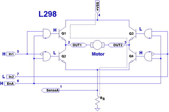
Figure 7-1. L298 full-bridge driver
The motor in the figure is driven when Q1 and Q4 are turned on. Q2 and Q3 are kept off when the other transistors are on. If Q1 and Q2 were allowed to be on at the same time, a short circuit would exist from VSS to ground. The and logic gates driving these transistors prevent this.
Returning to Figure 7-1, with Q1 and Q4 on, the current flows through the motor from left to right. Turning all transistors off results in no current flow. Turning Q3 and Q2 on causes the current to flow from VSS to ground, passing this time through the motor from right to left. By controlling pairs of transistors, current can be made to flow in one direction or the other.
Sensing Resistor
When used, the sensing resistor RS is a low-resistance resistor for sensing how much current flows through the motor (the datasheet suggests a non-wire-wound resistance of RS = 0.5 Ω). As current flow increases, the voltage VRS across the resistor increases. When the motor stalls, for example, VRS will exceed a certain threshold voltage, allowing protective circuitry to turn the drivers (and thus the motor) off. In this chapter, we will simply wire the sense pins to ground and omit the protective circuitry for simplicity.
Enable A and B
The L298 is a dual-bridge driver, with units A and B. Figure 7-1 shows only unit A. The enable inputs EnA and EnB enable or disable the drive to units A and B, respectively. Without a high signal on the enable input, no current will flow through the bridge, no matter what the other input signals are. The enable input can be used by the protective circuitry to disable the motor outputs, should the VRS voltage rise too high. Otherwise, the enable inputs can be tied to the logic high or controlled by the microprocessor.
Each half of the dual-bridge driver has a pair of logic inputs. They are In1 and In2 for bridge A, and In3 and In4 for bridge B. We’ll focus on bridge A.
When the enable EnA pin is enabled, the In1 and In2 inputs have the following results for the motor drive:
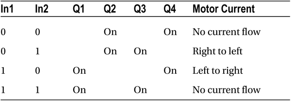
A simple way to think about this is that one input must be high, while the other is low for the motor drive. The direction is selected by the input that is high.
Protection Diodes
No inductive driver circuit is complete without protective diodes. When the applied voltage is suddenly removed from the motor coil, the magnetic field collapses, producing an electric current. Recall in Chapter 6 that the reverse-biased diode was used to bleed off the inductive kick in the unipolar motor drive.
Figure 7-2 shows the L298 with the external protective diodes wired in (these are not included in the IC). If the current flow was as shown in the earlier block diagram, the sudden off would cause the current to flow through diodes D3 and D2. The SGS-Thomson Microelectronics datasheet specifies that these should be 1A fast-recovery diodes (trr ≤ 200 ns). A slow-reacting diode can allow the voltage to spike into the surrounding circuit.
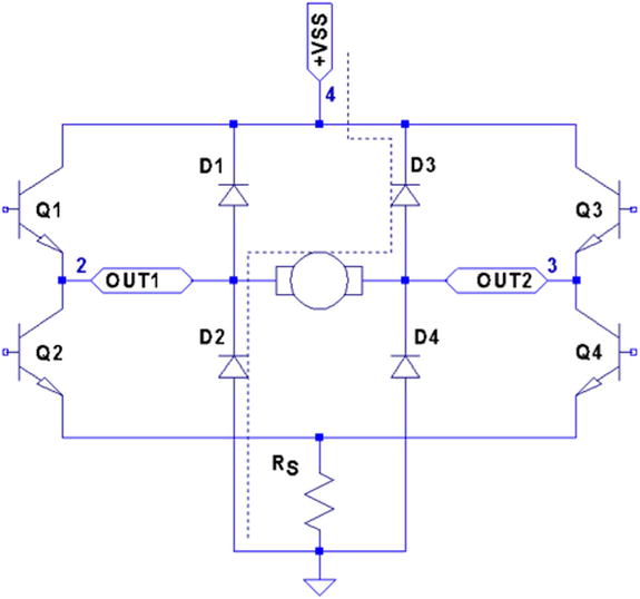
Figure 7-2. L298 with protective diodes
You could build your own L298 driver circuit, but with the availability of PCBs around $4 on eBay, you’d have to have a good reason to bother. Figure 7-3 shows the unit that I purchased and used for this project.

Figure 7-3. L298 driver PCB
![]() Note I purchased this PCB as an eBay Buy It Now offer with free shipping.
Note I purchased this PCB as an eBay Buy It Now offer with free shipping.
The PCB has three power connections:
- VS, which is labeled as +12 V (yellow wire in the photo)
- Gnd (black wire)
- VSS, which is labeled as +5 V (red wire)
This particular PCB has a jumper (removed in Figure 7-3), with its two pins visible just above the power-connection block and below the round capacitor. With the jumper installed, an onboard regulator supplies VSS with +5 V from the VS (+12 V) input. The regulated +5 V is also available for external circuitry at the block connector (where the red wire is shown).
When the motor (VS) voltage is higher than 12 V, it is best to remove the jumper and supply the +5 V into the block instead. The reason for this is that the linear regulator must dissipate additional heat from the higher input voltage. I am using a salvaged power supply with both a +5 V supply and a +16 V supply, so the jumper was removed.
To the right of the power-input block are header connection pins as follows:
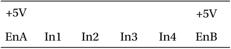
The EnA and EnB connections have jumpers installed to enable both driver units (tying the enable A and B inputs up to the +5 V supply). If you don’t need to control the enable inputs, leave the jumpers in. Otherwise, remove them and then use the edge pins for inputs to enables A and B.
The pins In1 through In4 are the inputs to the bridge drivers (see In1 and In2 in Figure 7-1).
The remaining connections are two blocks with paired connections:
- OUT1 and OUT2, bridge connections for unit A
- OUT3 and OUT4, bridge connections for unit B
You don’t have to install any protective diodes, since they are already included on the PCB. Price and convenience were the reasons I chose to buy the PCB. If you breadboard the driver instead, be sure to wire in the fast-acting protection diodes, since these are not included in the IC.
Driving from GPIO
Of course, before we attach the inputs of these drivers to the GPIO pins of the Raspberry Pi, we need to be certain that the voltage levels are safe and that the interface logic levels work.
The L298 IC has the following power requirements:
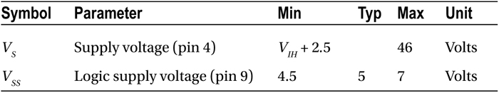
From this, we see that the motor side (VS) can operate up to 46 V. The logic side, however, must have a minimum of 4.5 V. In other words, the L298 driver operates at 5V TTL levels.
![]() Note Be sure to remove the regulator jumper when using high voltages.
Note Be sure to remove the regulator jumper when using high voltages.
But we’ve seen this kind of problem before, in Chapter 6. There we were still able to drive the ULN2003A safely from the GPIO outputs at 3 V levels. So let’s check the signal requirements of GPIO outputs vs. L298 inputs:
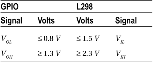
If you look carefully at the chart, there is a dodgy area where the GPIO output can be as low as VOH ≥ 1.3 V and still be in spec as far as the Raspberry Pi is concerned. We see that the L298 considers signals VIL ≤ 1.5V as a low. Worse, only voltages ≥ 2.3 V are considered high by the L298. The good news is that the L298 input current is very low:
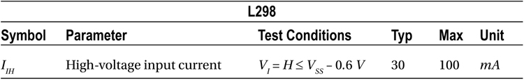
The input current necessary to drive the L298 input high is a maximum of 100 μA. The lowest configured output drive capability of a GPIO pin is 2 mA. The L298 input current requirement is thus only 5% of the minimum current drive available. If the GPIO pin had to drive a 2 mA signal, its output voltage might be as low as 1.3 V. But having to supply only 100 μA of signal current means that the GPIO voltage should be almost as high as it can go.
For this reason, it is not that unreasonable to expect the GPIO output voltage to be near 3 V (allowing for a drop from the +3.3 V supply). However, we must allow for variation in the +3.3 V power supply as well. If the supply is within the standard range of +3.125 to +3.465 V, and we allow a GPIO output drop of, say, 0.3 V due to the output transistor Ron, then the unloaded GPIO output voltage could be as low as 3.135 – 0.3 = 2.835 V. This is only 0.535 V above the minimum VIH = 2.3 V that we need for the L298. This is cutting things rather close, but sufficient for hobby and educational use (for products that are sold, you would want a greater margin for error). If this remains a concern for a project build, external pull resistors to +3.3 V can be added.
The DMM Check
The final word is the voltage measurement of the L298 chip’s inputs. You must make certain there is no pull-up resistor to +5 V on the PCB. The datasheet doesn’t indicate that any L298 chip internal pull-up resistors exist. But seeing is believing, so don’t skip this check. A purchased PCB is more likely to contain pull-up resistors than not.
Without attaching it to the Pi, supply the circuit with +5 V for its logic (the motor supply need not be applied). When using the onboard regulator, supply the +12 V to the +VS input instead. Then check the voltage appearing at the EnA, EnB, In1, In2, In3, and In4 inputs. When measured, there should be nearly no voltage present (with respect to ground). If you read +5 V instead, the PCB likely has provided a pull-up resistor somewhere. For the enable inputs, jumpers may need to be removed. Do not wire these inputs to the Raspberry Pi until these inputs have passed this check. Anything measured less than 0.6 V is probably OK. Measurements higher than this probably mean a defective driver IC or a wiring error.
If you are supplying the L298 logic from a separate +5 V supply, it is a good idea to perform one more test with the +12 V (or higher) motor supply applied. The measured voltage at each input pin should remain as before, near zero. Anything else suggests a bad PCB or defective L298 chip leaking current into the inputs.
Before we look at the schematic and software, let’s review how the bipolar stepper motor works. There are three basic modes of operation for a bipolar stepper motor:
- Wave drive, one-phase-on drive
- Wave drive, two-phase-on drive
- Half-step drive
One-Phase-On Mode
Figure 7-4 shows the first two of four possible drive states for wave drive, one phase on. Each winding is energized in turn for the first two steps. The final two steps energize the same two windings in sequence except that the current polarity is reversed. In other words, the south pole of the rotor follows the positive input polarity (as wired in the figure). In this mode, there are a total of four steps.
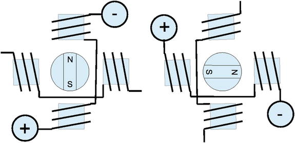
Figure 7-4. Wave drive, one phase on
This simple mode of operation suffers from the loss of precision that the half-step drive has and lacks the torque of two-phase-on mode.
Two-Phase-On Mode
Wave drive, two-phase-on mode energizes both windings for each step. This is where the extra torque comes from. Figure 7-5 shows two of the four possible steps for this mode. Notice how the south pole centers itself between two poles, as it follows the two positive polarities. Like the one-phase mode, there are only four possible steps.
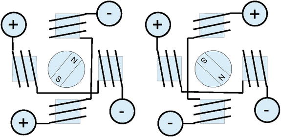
Figure 7-5. Wave drive, two phase on
While this mode lacks the precision of half-step mode (next), it does enjoy the extra torque advantage over all three modes.
Half-Step Mode
In half-step mode, a combination of the two prior modes is used. First, only one winding is energized to point the rotor at the winding’s pole (like one-phase mode). Then the next pole is energized while keeping the prior winding energized. In this way, the rotor moves a half step between the two poles, as with two-phase mode. Finally, the previous winding is turned off, producing another half step. The precision is increased to a total of eight steps in this manner.
This is clearly the most precise of the three modes. While it lacks some of the torque of two-phase mode, it has on average more torque than one-phase mode.
In all of these modes, it is necessary to first pass current through the windings in one direction, and then later in the reverse direction. This allows the bipolar stepper motor to be built with less wire than the unipolar motor. In the unipolar design, only one or two of the four center-tapped windings are used at one time. Consequently, the bipolar motor is cheaper to manufacture and lighter in weight.
Figure 7-6 illustrates my test setup. At the left is a power supply that I rescued from a discarded piece of equipment. To the right of the Raspberry Pi station, I have the L298 PCB wired up to the power and the Pi’s GPIO pins. The remaining four wires go from the drive PCB to the bipolar stepper motor (I left some sort of shaft attachment to the motor, to make the rotation more visible).
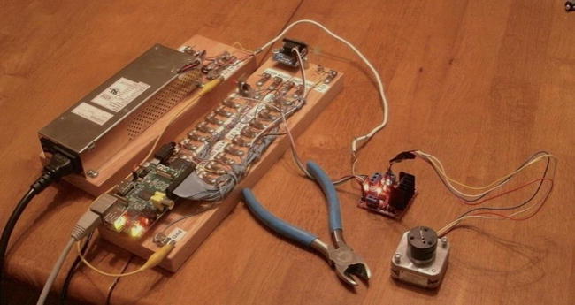
Figure 7-6. My bipolar stepper motor setup
Choosing Driving GPIOs
Recall from Chapter 6’s Table 6-1 that some GPIO pins are more suitable than others for motor controls. While the Raspberry Pi is booting up, we don’t want driver circuits and motors running amok. It is best that the motor remains disabled until the Pi boots up and the motor-controlling software takes proper control.
When using the L298, we can take one of two design approaches:
- Tie enable inputs high, but choose motor-safe GPIO pins for the driver inputs.
- Drive the enable inputs from a motor-safe GPIO and configure the other GPIO pins after boot-up.
The first option does not use the enable inputs at all. For that, you must make sure that all In GPIO pins are safe for motor control at boot time. The disadvantage is that all four input controls need to be taken from the safe GPIO pool. If you need to drive more than one motor, your options start to become limited.
The second approach uses motor-safe GPIO pin(s) on the two enable inputs of the L298 driver. This way, the enable inputs are pulled down during the boot-up process, disabling the motor controls, regardless of the state of the In pins. This gives you flexibility to choose any other GPIO pins for use for the In signals. This is the approach adopted for this chapter’s project. (Note that you can tie the enable pins together so that only one safe GPIO pin is required to drive the enable input.) Because a bipolar stepper motor needs a bridge driver for each of its two windings, we’ll use both bridge driver units provided by the L298 IC.
The enable inputs for the two windings can be ganged together and driven by one GPIO pin. This, of course, increases the load on the GPIO output, but at a worst case of 200 μA, the driving voltage requirements will be easily met.
Project Schematic
Figure 7-7 shows the schematic for the bipolar motor driver. If you are using a purchased PCB, the only important details are the connections to it. The schematic, however, helps us visualize all the separate components involved.
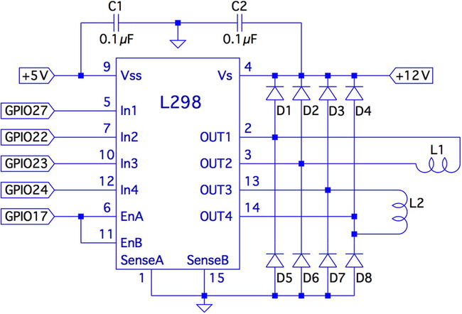
Figure 7-7. L298 schematic
In this circuit, the enable inputs A and B have been tied together so that only GPIO 17 needs to be allocated to drive it.
Junk-Box Motors
If you’ve been an electronics hobbyist for a while, you likely have a bipolar motor in your junk box. If not, salvage one from an old 3.5-inch floppy disk. Its seek motor will likely be a bipolar stepper. Another source of stepper motors is an old flat-top scanner.
Bipolar motors are easier to figure out than unipolar motors. There are only four wires, and they operate in pairs. To identify the pairs, simply take resistance readings. A low reading will identify one pair of wires. Once that pair is identified, the remaining two wires should be the second pair and read similarly. Make sure there is no connection between the windings. They should be electrically isolated from each other.
Program Operation
The program used in this chapter is named bipolar.c and is listed at the end of the chapter. The program is designed similarly to the unipolar program in Chapter 6. The bipolar program, however, does not do clock positioning, but instead operates in free-running mode when instructed to do so.
The program starts in one-phase mode, but the stepper-motor mode can be changed with any of the following single-character commands:
|
Character |
Command |
|---|---|
|
1 |
Wave mode, one phase |
|
2 |
Wave mode, two phase |
|
3 |
Half-step mode |
Entering a mode command will automatically stop the motor if it is in free-running mode.
To test your motor connections, these single-step commands are available:
|
Character |
Command |
|---|---|
|
+ |
Single step clockwise |
|
- |
Single step counterclockwise |
The + command steps the motor one step clockwise, while the – (minus) key steps the motor counterclockwise. If your motor turns the wrong way, you can fix your wiring after testing it.
Similarly, use these single-step commands to make sure your motor is wired up correctly. In one-phase mode (the default), the motor should step equally with each + or - step command. If not, one of the two pairs needs its connections reversed.
The free-running commands (and Quit) are listed here:
|
Character |
Command |
|---|---|
|
F |
Forward (free running) |
|
R |
Reverse (free running) |
|
S |
Stop |
|
> |
Go faster (halve the step time) |
|
< |
Go slower (double the step time) |
|
Q |
Quit |
Entering F starts the motor running, in the forward (clockwise) direction. To speed it up, press > while it is running, or prior to starting it. Pressing the same direction command F toggles the motor off again. Alternatively, S is available to stop the motor if that seems more intuitive. The R command starts the motor in the reverse direction. Pressing R again stops it. Direction can be changed while the motor is running. This tests how well it recovers when operated at higher speeds.
Program Internals
This program requires the use of a thread to run the motor in free-running mode. This design allows the main program to continue to read user commands from the keyboard while supplying the motor with stepping commands. The user can change the stepping speed, reverse the motor, or stop the motor.
The main user input dispatch loop is in the main program (lines 230 to 305). The threaded code resides in lines 125 to 140. Unless the free-running F or R commands are in effect, the thread blocks in line 131, waiting for a command. Once a command is received, the loop in lines 133 to 136 keeps the motor stepping, until the main loop sets the stop flag.
The mutex and cond variables (lines 36 and 37) provide a simple arrangement to implement a queue from the main thread to the free-running thread. The queue get function is implemented in lines 105 to 119. The code must first successfully lock the mutex in line 109. Once that is accomplished, the while loop in lines 111 and 112 is executed. If the cmd variable is still zero, this indicates that no command has been queued. When that happens, pthread_cond_wait() in line 112 is executed. This unlocks the mutex and blocks the execution of the program. Control blocks until the cond variable is signaled in line 158. When control returns from pthread_cond_wait(3), the kernel has relocked the mutex.
Queuing the command occurs in the routine queue_cmd() (lines 146 to 159). After locking the mutex (line 149), the while loop checks whether the cmd variable is nonzero. If it is, this indicates that the motor thread has not received the last command yet, and control blocks in the pthread_cond_wait() call (line 152). Again, when control blocks, the kernel releases the mutex. The cond variable is signaled from line 117, when the command is taken off the one-element queue.
The stepping functions are performed by the routine step() in lines 73 to 91. The motor drive is disabled in line 86 so the GPIO signals can be changed (line 87). Once the new GPIO output settings are established, the drive to the motor is enabled in line 88.
If you choose to use different GPIO pins for this project, change the constant declarations in lines 23 to 27.
1   /*********************************************************************
2    * bipolar.c : Drive a bipolar stepper motor
3    *********************************************************************/
4
5   #include <stdio.h>
6   #include <stdlib.h>
7   #include <fcntl.h>
8   #include <unistd.h>
9   #include <errno.h>
10  #include <math.h>
11  #include <ctype.h>
12  #include <termio.h>
13  #include <sys/mman.h>
14  #include <pthread.h>
15  #include <assert.h>
16
17  #include "gpio_io.c"                  /* GPIO routines */
18  #include "timed_wait.c"               /* timed_wait() */
19
20  /*
21   * GPIO definitions :
22   */
23  static const int g_enable    = 17;  /* L298 EnA and EnB */
24  static const int g_in1   = 27;      /* L298 In1 */
25  static const int g_in2   = 22;      /* L298 In2 */
26  static const int g_in3   = 23;      /* L298 In3 */
27  static const int g_in4   = 24;      /* L298 In4 */
28
29  static volatile int stepper_mode = 0;      /* Stepper mode − 1 */
30  static volatile float step_time = 0.1;     /* Step time in seconds */
31
32  static volatile char cmd = 0;       /* Thread command when nonzero */
33  static volatile char stop = 0;      /* Stop thead when nonzero */
34  static volatile char stopped = 0;   /* True when thread has stopped */
35
36  static pthread_mutex_t mutex;       /* For inter−thread locks */
37  static pthread_cond_t cond;         /* For inter−thread signaling */
38
39  /*
40   * Await so many fractional seconds
41   */
42  static void
43  await(float seconds) {
44           long sec, usec;
45
46           sec = floor(seconds);                /* Seconds to wait */
47           usec = floor((seconds−sec)*1000000); /* Microseconds */
48           timed_wait(sec,usec,0);              /* Wait */
49  }
50
51  /*
52   * Enable/Disable drive to the motor
53   */
54  static inline void
55  enable(int enable) {
56           gpio_write(g_enable, enable);
57  }
58
59  /*
60   * Drive the appropriate GPIO outputs :
61   */
62  static void
63  drive(int L1L2) {
64           gpio_write(g_in1, L1L2&0x08);
65           gpio_write(g_in2, L1L2&0x04);
66           gpio_write(g_in3, L1L2&0x02);
67           gpio_write(g_in4, L1L2&0x01);
68  }
69
70  /*
71   * Take one step in a direction :
72   */
73  static void
74  step(int direction) {
75           static const int modes[3][8] = {
76                   { 0b1000, 0b0010, 0b0100, 0b0001 },      /* Mode 1 */
77                   { 0b1010, 0b0110, 0b0101, 0b1001 },      /* Mode 2 */
78                   { 0b1000, 0b1010, 0b0010, 0b0110, 0b0100, 0b0101,
                       0b0001, 0b1001 }
79           } ;
80           static int stepno = 0;            /* Last step no.*/
81           int m = stepper_mode < 2 ? 4 : 8; /* Max steps for mode */
82
83           if ( direction < 0 )
84                   direction = m − 1;
85
86           enable(0);                          /* Disable motor */
87           drive(modes[stepper_mode][stepno]); /* Change fields */
88           enable(1);                          /* Drive motor */
89
90           stepno = (stepno+direction) % m; /* Next step */
91  }
92
93  /*
94   * Set the stepper mode of operation :
95   */
96  static inline void
97  set_mode(int mode) {
98           enable(0);
99           stepper_mode = mode;
100 }
101
102 /*
103  * Take a command off the input queue
104  */
105  static char
106  get_cmd(void) {
107          char c;
108
109          pthread_mutex_lock(&mutex);
110
111          while ( !cmd)
112                  pthread_cond_wait(&cond,&mutex);
113
114          c = cmd;
115          cmd = stop = 0;
116          pthread_mutex_unlock(&mutex);
117          pthread_cond_signal (&cond); /* Signal that cmd is taken */
118
119          return c;
120 }
121
122 /*
123  * Stepper controller thread :
124  */
125 static void *
126 controller(void * ignored) {
127          int command;
128          int direction;
129
130          for ( stopped = 1; ; ) {
131                  command = get_cmd();
132                  direction = command == 'F' ? 1 : −1;
133
134                  for ( stopped = 0; !stop;) {
135                          step(direction);
136                          await(step_time);
137                  }
138                  stopped = 1;
139          }
140          return 0;
141 }
142
143 /*
144  * Queue up a command for the controller thread :
145  */
146 static void
147 queue_cmd(char new_cmd) {
148
149         pthread_mutex_lock(&mutex); /* Gain exclusive access */
150
151         /* Wait until controller grabs and zeros cmd */
152         while ( cmd)
153                 pthread_cond_wait(&cond ,&mutex);
154
155         cmd = new_cmd;                 /* Deposit new command */
156
157         pthread_mutex_unlock(&mutex);  /* Unlock */
158         pthread_cond_signal(&cond);    /* Signal that cmd is there */
159 }
160
161 /*
162  * Stop the current operation :
163  */
164 static void
165 stop_cmd(void) {
166          for ( stop = 1; !stopped; stop = 1)
167                  await(0.100);
168 }
169
170 /*
171  * Provide usage info :
172  */
173 static void
174 help(void) {
175           puts("Enter :
"
176                    "  1 − One phase mode
"
177                    "  2 − Two phase mode
"
178                    "  3 − Half step mode
"
179                    "  R − Toggle Reverse (counter−clockwise)
"
180                    "  F − Toggle Forward (clockwise)
"
181                    "  S − Stop motor
"
182                    "  + − Step forward
"
183                    "  − − Step backwards
"
184                    "  > − Faster step times
"
185                    "  < − Slower step times
"
186                    "  ? − Help
"
187                    "  Q − Quit
 ") ;
188 }
189
190 /*
191  * Main program
192  */
193 int
194 main(int argc,char **argv) {
195          pthread_t tid;    /* Thread id */
196          int tty = 0;      /* Use stdin */
197          struct termios sv_ios, ios;
198          int rc, quit;
199          char ch, lcmd = 0;
200
201          rc = tcgetattr (tty,&sv_ios);    /* Save current settings */
202          assert(!rc);
203          ios = sv_ios;
204          cfmakeraw(&ios);          /* Make into a raw config */
205          ios.c_oflag = OPOST | ONLCR; /* Keep output editing */
206          rc = tcsetattr(tty,TCSAFLUSH,&ios); /* Put into raw mode */
207          assert(!rc);
208
209          /*
210           * Initialize and configure GPIO pins :
211           */
212          gpio_init();
213          gpio_config(g_enable,Output);
214          gpio_config(g_in1,Output);
215          gpio_config(g_in2,Output);
216          gpio_config(g_in3,Output);
217          gpio_config(g_in4, Output);
218
219          enable(0);                   /* Turn off output */
220          set_mode(0);                 /* Default is one phase mode */
221
222          help();
223
224          pthread_mutex_init(&mutex,0);     /* Mutex for inter−thread
             locking */
225          pthread_cond_init(&cond,0);  /* For inter−thread signaling */
226          pthread_create(&tid,0,controller,0); /* The thread itself */
227
228          /*
229           * Process single-character commands :
230           */
231          for ( quit=0; !quit;) {
232                  /*
233                   * Prompt and read input char :
234                   */
235                  write(1,": ",2);
236                  rc = read(tty,&ch,1);
237                  if ( rc != 1 )
238                          break;
239                  if ( islower (ch))
240                          ch = toupper(ch);
241
242                  write(1,&ch,1);
243                  write(1,"
",1);
244
245                  /*
246                   * Process command char :
247                   */
248                  switch ( ch) {
249                  case '1' :    /* One phase mode */
250                          stop_cmd();
251                          set_mode(0);
252                          break;
253                  case '2' :    /* Two phase mode */
254                          stop_cmd();
255                          set_mode(1);
256                          break;
257                  case '3' :    /* Half step mode */
258                          stop_cmd();
259                          set_mode(2);
260                          break;
261                  case '<' :    /* Make steps slower */
262                          step_time *= 2.0;
263                          printf("Step time is now %.3f ms
",step_
                             time*1000.0);
264                          break;
265                  case '>' :    /* Make steps faster */
266                          step_time /= 2.0;
267                          printf("Step time is now %.3f ms
",step_
                             time*1000.0);
268                          break;
269                  case 'F' :   /* Forward : run motor */
270                          if ( !stopped && lcmd != 'R') {
271                               stop_cmd();       /* Stop due to toggle */
272                                  lcmd = 0;
273                          } else  {
274                     op_cmd();       /* Stop prior to change direction */
275                                  queue_cmd(lcmd='F'),
276                          }
277                          break;
278                  case 'R' :    /* Reverse : run motor */
279                          if ( !stopped && lcmd != ’F’) {
280                                  stop_cmd();
281                                  lcmd = 0;
282                          } else  {
283                                  stop_cmd();
284                                  queue_cmd(lcmd=’R’);
285                          }
286                          break ;
287                  case 'S' :     /* Just stop */
288                          stop_cmd();
289                          break;
290                  case '+' :     /* Step clockwise */
291                  case '=' :     /* So we don’t have to shift for + */
292                          stop_cmd();
293                          step(1);
294                          break;
295                  case '−' :     /* Step counterclockwise */
296                          stop_cmd();
297                          step(−1);
298                          break;
299                  case 'Q' :      /* Quit */
300                          quit = 1;
301                          break;
302                  default :       /* Unsupported */
303                          stop_cmd();
304                          help();
305                  }
306          }
307
308          stop_cmd();
309          enable(0);
310
311          puts("
Exit.");
312
313          tcsetattr(tty,TCSAFLUSH,&sv_ios); /* Restore terminal mode */
314          return 0;
315 }
316
317 /* End bipolar.c */