Chapter 2: Combinational Logic
Designs are typically composed of combinational and sequential logic. Combinational logic is made up simply of gates, as we saw in Chapter 1, Introduction to FPGA Architectures and Xilinx Vivado. Sequential logic maintains state, usually based on a clock edge, but it can be level-based as well, as we will discuss when we learn what not to do when inferring sequential logic.
In this chapter, we are going to explore writing a complete SystemVerilog module from scratch that can perform some basic real-world operations that you may use one day in your actual designs.
In this chapter, we are going to cover the following main topics:
- Creating SystemVerilog modules
- Introducing data types
- Packaging up code using functions
- Project – creating combinational logic
Technical requirements
The technical requirements for this chapter are the same as those for Chapter 1, Introduction to FPGA Architectures and Xilinx Vivado.
To follow along with the examples and the project, please take a look at the code files for this chapter at the following GitHub repository: https://github.com/PacktPublishing/Learn-FPGA-Programming/tree/master/CH2.
Creating SystemVerilog modules
At the heart of every design are the modules that compose it. From the testbench that's used to verify the design to any instantiated components, they are all declared somewhere as a module. For the example design we'll be covering in this chapter, we'll be creating a set of modules representing the functions that we can access via the buttons and switches on the evaluation board. We'll use these switches to set values, and we'll use five buttons to perform operations.
Let's take a look at the components of a module declaration:
module project_2
#(parameter SELECTOR,
Parameter BITS = 16)
(input wire [BITS-1:0] SW,
input wire BTNC,
input wire BTNU,
input wire BTNL,
input wire BTNR,
input wire BTND,
output logic signed [BITS-1:0]);
We are creating a module called project_2, which will be the top level of our design. The first section within #() is the parameter list, which allows us to define parameters that we can use within the port list or module. We can also define parameters anywhere within the module, and they can also be overridden during instantiation. However, parameters must be defined prior to use.
How to create reusable code – parameters
Parameters can be used to override information in a module's instantiation. This information can be used within the module to control the size of the data, as is the case with BITS, which has a default value of 16 if it's not overridden. Parameters can also control the instantiation of logic or modules, as we'll see when we explore the case statement. We can also create a parameter, SELECTOR, which has no default. This is a good way to make sure that something is set in the instantiation since there is no default. If it is not overridden, it will result in an error.
Parameters can be integers, strings, or even types:
#(parameter type SW_T = logic unsigned [15:0], …
(input SW_T SW, …
Here, we created a type, SW_T, that defaults to logic unsigned [15:0] and creates a port using this type, SW. When the module is instantiated, a new type can be passed, thus overriding the default and allowing for greater design reuse.
Tip
It is good practice to keep parameters intended to be overridden within the parameter list and use localparams, which cannot be overridden, within the module itself. Parameters provide us with a great way to express design intent. When you return to a design after a long period of time, magic numbers such as 3.14 have much less meaning than pi.
Let's take a look at the data types we'll be using in SystemVerilog for data movement.
Introducing data types
All computer programming languages need variables. These are places in memory or registers that store values that the program that's running can access. Hardware Design Languages (HDLs) are a little different in that you are building hardware. There are variable equivalents in terms of storage/sequential logic, which we'll discuss in the next chapter, but we also need wires to move data around the hardware we're building using the FPGA routing resources, even if they are never stored:

Figure 2.1 – Program flow versus HDL flow
As we can see, in a traditional flow, you have a computer that has a processor and memory. The program flows linearly; however, with modern machines, there are increasing levels of parallelism. When you write SystemVerilog, you are using data types to create hardware that will store or move data around physically from Lookup Tables (LUTs) to LUTs. If you want to use external memory, which is something we will introduce in Chapter 8, Lots of Data? MIG and DDR2, you need to implement the hardware to communicate with the memory.
Introducing built-in data types
SystemVerilog has multiple built-in types, but the most interesting ones for design are the logic and bit type:
- logic: We used this type in the previous chapter. The logic type can represent a 0, 1, x (undefined or treated as don't care, as we'll see shortly), or z (tri-state or also a don't care).
Important note
If you've ever used verilog, you will know of the reg type. This was a confusing type to new HDL designers as they would see reg and think it's short for register. In fact, a reg type was any signal originating from an always block, even though always blocks could be used to generate combinational logic, as we'll see shortly. Although reg can still be used for backward compatibility, you would be better off using logic or bit, which can be used in both assign statements and always blocks. The logic type also allows for the propagation of x through a design. This can be helpful for debugging startup conditions.
- bit: The bit type uses less memory to store than logic, but it can only store a 0 or 1. This allows for lower memory usage and potentially faster simulation at the expense of tracking undefined values.
There are also four other, lesser used two state types:
- byte: 8 bits
- shortint: 16 bits
- int: 32 bits
- longint: 64 bits
Important note
The differences between bit and logic are purely related to how they behave in simulation. Both types will generate the same logic and storage elements in hardware. All the other types only differ in size or default sign representation.
With that, we've looked at the basic types. But what if we need to deal with different sizes of data or more data than the types can handle?
Creating arrays
The reason that byte, shortint, int, and longint are not used as much is because typically, you will size your signals as needed; for example:
bit [7:0] my_byte; // define an 8 bit value
Here, my_byte is defined as a packed 8-bit value. It's possible to also create an unpacked version:
bit my_byte[8]; // define an 8 bit value
Packed versions have the advantage of slicing into arrays, while unpacked versions have the advantage of inferring memories, as we'll discuss in Chapter 5, FPGA Resources and How to Use Them.
Arrays can also have multiple dimensions:
bit [2:0][7:0] my_byte[1024][768]; // define an 8 bit value
// 3 4 1 2 Array ordering
The ordering of the array is defined in the preceding code. The following are valid ways to access the array:
my_array[0][0] Returns a value of [2:0][7:0]
my_array[1023][767][2] Returns an 8 bit value
Defining an array can be done using a range, such as [7:0], or a number of elements, such as [1024].
Querying arrays
SystemVerilog provides system functions for accessing array information. As we'll see in this project, this allows for reusable code.
Important note
The dimension parameter is optional and defaults to 1.
This becomes even more important when we want to implement type parameters:

These system functions allow us to query an array to get its parameters.
Assigning to arrays
When we want to assign a value to a signal defined as an array, we should size it properly to avoid warnings. If we don't specify a size, then the size defaults to 32 bits, which was part of the Verilog Language Reference Manual (LRM).
There are three ways we can assign without providing a sign: '1 assigns all bits to 1, '0 assigns all bits to 0, and 'z assigns all bits to z. If we have a single packed dimension, we can use n'b to specify a binary value of n bits, n'd to specify a decimal value of n bits, or n'h to specify a hex value of n bits:
logic [63:0] data;
assign data = '1; // same as data = 64'hFFFFFFFFFFFFFFFF;
assign data = '0; // same as data = 64'd0;
assign data = 'z; // same as data = 64'hzzzzzzzzzzzzzzzz;
assign data = 0; // data[31:0] = 0, data[63:32] untouched.
It's important to remember that n in these cases is the number of bits, not the number of digits.
Handling multiple-driven nets
There is one other type that deserves to be mentioned, although we will not be using it for a while. This is a wire. The wire type represents 120 different possible values; that is, the four basic values – 0, 1, x, and z – and drive strengths. The wire type has what is known as a resolution function. Wire types are the only signals that can be connected to multiple drivers. We will see this when we introduce the Serial Peripheral Interface (SPI) protocol and access the DDR2 memory on the Nexys A7 board:
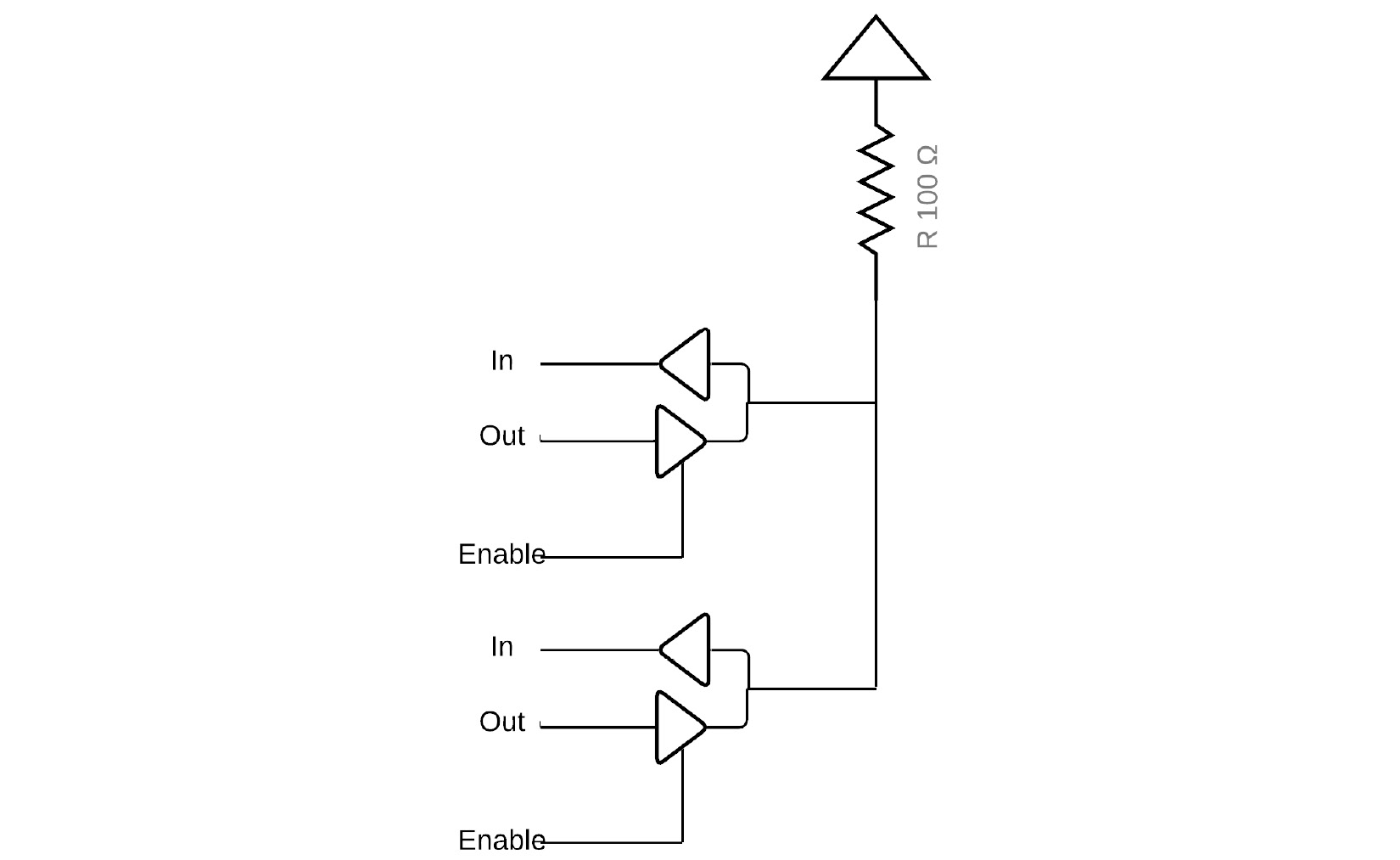
Figure 2.2 – Tri state example
FPGAs, in general, do not have internal tri-state capabilities. The preceding example shows two devices each with tri-state Input/Output (I/O) buffers connected:
logic [1:0] in;
logic [1:0] out;
logic [1:0] enable;
tri1 R_in;
assign R_in = (enable[0]) ? out[0] : 'z;
assign R_in = (enable[1]) ? out[1] : 'z;
assign in[0] = R_in;
assign in[1] = R_in;
The preceding code demonstrates how the two tri-state buffers are constructed. tri1 is a testbench construct where a signal is declared as a tri-state with a weak pullup to 1.
Handling signed and unsigned numbers
Verilog had just one signed signal type, integer. SystemVerilog allows us to define both unsigned and signed numbers explicitly for any built-in type:
bit signed [31:0] signed_vect; // Create a 32 bit signed value
bit unsigned [31:0] unsigned_vect; // create a 32 bit unsigned value
When performing signed arithmetic, it's important to make sure the sizing is correct. Also, when computing with signed numbers, you should make sure all the signals involved are signed so that the correct result is obtained.
Important note
Digital logic, such as computer processors or FPGA implementations, use 2's complement to represent signed numbers. What this means is that to negate a number, you simply invert it and add 1. For example, to get -1 in 2's complement, assuming there's 4 bits for representation, we would take 4'b0001, invert it to get 4'b1110, and add 1, resulting in 4'b1111. Bit 3 is the sign bit, so if it's 0, the number is positive and 1 if it's negative. This also means that the maximum number of signed values that we can represent by using 4 bits is 4'b0111 or +7 and 4'b1000 or -8.
Adding bits to a signal by concatenating
SystemVerilog provides a powerful concatenation function, {}, for adding bits or signals to create larger vectors or replication. When casting an unsigned integer to a signed integer, typically, you'll want to use the concatenation operator, {}, to prepend 1'b0 into the sign bit so that the resulting signal remains unsigned. The concatenation operator can be used to merge multiple signals together, such as {1'b0, unsigned_vect}. It can also be used to replicate signals. For example, {2{unsigned_vect}} would be equivalent to {unsigned_vect, unsigned_vect}.
Casting signed and unsigned numbers
You can cast an unsigned number to a signed number by using the signed' keyword, and cast a signed number to an unsigned number using the unsigned' keyword:
logic unsigned [15:0] unsigned_vect = 16'hFFFF;
logic unsigned [15:0] final_vect;
logic signed [16:0] signed_vect;
logic signed [15:0] signed_vect_small;
assign signed_vect = signed'({1'b0, unsigned_vect}); // +65535
assign signed_vect_small = signed'(unsigned_vect); // -1
assign unsigned_vect = unsigned'(signed_vect);
assign final_vect = unsigned'(signed_vect_small); // 65535
Here, you can see that an unsigned 16-bit number can go from 0 to 65535. A 16-bit signed number can go from -32768 to 32767, so if we assign a number larger than 32767, it would have its sign bit set in the same-sized signed number, causing it to become negative.
These are equivalent to the verilog system functions; that is, $signed() and $unsigned(). However, it's preferable to use the casting operators.
Important note
When casting signed to unsigned or unsigned to signed, pay attention to sizing. For example, to maintain the positive nature of unsigned, typically, you'll use the concatenation operator, {}, as in signed({1'b0, unsigned_vect});, which means the resulting signal will be 1 bit larger. When going from signed to unsigned, care must be taken to ensure that the number is positive; otherwise, the resulting assignment will not be correct. You can see an example of mismatched assignments in the preceding code, where signed_vect_small becomes -1 rather than 65535 and final_vect becomes 65535, even though signed_vect_small is -1.
Creating user-defined types
We can create our own types using typedef. A common example that's used in SystemVerilog is to create a user-defined type for speeding up simulations. This can be done by using a define:
`ifdef FAST_SIM
typedef bit bit_t
`else
typedef logic bit_t
`endif
If FAST_SIM is defined, then any time we use bit_t, the simulator will use bit; otherwise, it will use logic. This will speed up simulations.
Tip
It is a good idea to adopt a naming convention when creating types – in this case, _t. This helps you identify user-defined types and avoid confusion when using the type within your design.
Accessing signals using values with enumerated types
When it comes to readability, it's often preferable to use variables with values that make more sense and are self-documenting. We can use enumerated types to accomplish this, like so:
enum bit [1:0] {RED, GREEN, BLUE} color;
In this case, we are creating a variable, color, made up of the values RED, GREEN, and BLUE. Simulators will display these values in their waveforms. We'll discuss enumerated types in more detail in Chapter 3, Counting Button Presses.
Packaging up code using functions
Often, we'll have code that we will be reusing within the same module or that's common to a group of modules. We can package this code up in a function:
function [4:0] func_addr_decode(input [31:0] addr);
func_addr_decode = '0;
for (int i = 0; i < 32; i++) begin
if (addr[i]) begin
return(i);
end
end
endfunction
Here, we created a function called func_addr_decode that returns a 5-bit value. function takes a 32-bit input called address. Functions can have multiple outputs, but we will not be using this feature. To return the function's value, you can assign the result to the function name or use the return statement.
Creating combinational logic
The two main ways of creating logic are via assign statements and always blocks. assign statements are convenient when creating purely combinational logic with only a few terms. This is not to say the resulting logic will necessarily be small. For instance, you could create a large multiply accumulator using a single line of code, or large combinational structures by utilizing an assign statement and calling a function:
assign mac = (a * b) + old_mac;
assign addr_decoder = func_addr_decode(current_address);
An always block allows for more complex functionality to be defined in a single process. We looked at always blocks in the previous chapter. There, we were using a sensitivity list in the context of a testbench. Sensitivity lists allow an always block to only be triggered when a signal in the list changes. Let's look back at the testbench that was provided in Chapter 1, Introduction to FPGA Architectures and Xilinx Vivado:
always @(SW, LED) begin
In this example, the always block would only be triggered when SW or LED transitions from one state to another.
Important note
Sensitivity lists are not synthesizable and are only useful in testing. always_comb is recommended when describing synthesizable code in an always block.
When we write synthesizable code using an always block, we use the always_comb structure. This type of code is synthesizable and recommended for combinational logic. The reason is that always_comb will create a warning or error if we inadvertently create a latch.
Important note
A note about latches: They are a type of storage element. They are level-sensitive, meaning that they are transparent when the gating signal is high, but when the gating signal transitions to low, the value is held. Latches do have their uses, particularly in the ASIC world, but they should be avoided at all costs in an FPGA as they almost always lead to timing problems and random failures. That being said, we will demonstrate how a latch works and why it can be bad as part of this chapter's project.
There are a few different operations that can go within an always block. Since we are generating combinational logic, we must make sure that all the possible paths through any of these commands are covered. We will discuss this later.
Handling assignment operators
There are two basic types of assignments in SystemVerilog: blocking and non-blocking. Because we are writing in an HDL, we need to be able to model the hardware we are creating. All the hardware you design will be effectively running in parallel inside the FPGA.
Creating multiple assignments using non-blocking assignments
In hardware, whenever you create multiple always blocks, they are all executing at the same time. Since this is effectively impossible on a normal computer running linearly or, at best, a few threads in parallel, we need a way to model parallel behavior. Simulators accomplish this by using a scheduler that splits up simulation time into delta cycles. This way, if multiple assignments are scheduled to happen, there is still a linear flow to them. This makes handling blocking and non-blocking assignments critical.
A non-blocking assignment is something that is scheduled to occur within a delta when the simulator's time advances. We will discuss non-blocking in more detail in Chapter 3, Counting Button Presses.
Using blocking assignments
Blocking assignments occur immediately. With rare exception, usually only with regards to testbenches, all assignments within an always_comb block will be blocking.
There are several blocking assignments in SystemVerilog:

There are also some shortcuts for incrementing or decrementing signals.
Incrementing signals
Here's a list of the shortcuts for incrementing:
- Pre-increment, ++i, increments the value of I before using it
- Post-increment, i++, increments I after using it
- Pre-decrement, --i, increments the value of I before using it
- Post-decrement, i--, increments I after using it
Now that we've learned how to manipulate values, let's learn how to use these variables to make decisions.
Making decisions – if-then-else
One of the basics of any programming language is to control the flow through any operation. In the case of an HDL, this is generating the actual logic that will be implemented in the FPGA fabric. We can view an if-then-else statement as a multiplexor, the conditional expression of the if statement the select lines. Let's take a look at it in its simplest form:
if (add == 1) sum = a + b;
else sum = a - b;
This will essentially select whether b will be added or subtracted from a based on whether the add signal is high. A simplified view of what could be generated is shown in the following diagram:

Figure 2.3 – An if-then-else representation
In all likelihood, the logic will be implemented in a much less expensive way. It's worth looking at the results of your designs as they are built to understand the kind of optimizations that occur.
Comparing values
SystemVerilog supports normal equality operations such as == and !=. These operators check if two sides of a comparison are equal or not equal, respectively. Since we are dealing with hardware and there is the possibility of us having undefined values, there is a disadvantage to these operators in that x's can cause a match, even if it's not intended, by falling through to the else clause. This is usually more of an issue in testbenches. There are versions of these operators that are resistant to x's; that is, === and !==. In a testbench, it is advised to use these operators to avoid unanticipated matches.
Comparing wildcard equality operators
It is also possible to match against ranges of values. This is possible using the =?= and !?= operators. These allow us to use wildcards in the match condition. For example, say you had a 32-bit bus, but needed to handle odd aligned addressing:
if (address[3:0] =?= 4'b00zz) slot = 0;
else if (address[3:0] =?= 4'b01zz) slot = 1;
The wildcard operators allow you to do this. The preceding examples would ignore the lower two bits.
Qualifying if statements with unique or priority
Normally, when thinking of an if statement, you think of each if evaluation as a separate comparison relying on the previous ifs that came before it. This type of if statement is a priority, meaning that the first if that matches will evaluate to true. In the simple example shown previously, we can see that we are looking at the same address and masking out the lowest two bits. Often, during optimization, the tool will realize that the if statements cannot overlap and will optimize the logic accordingly. However, if we know this to be the case, we can use the unique keyword to tell Vivado that each if doesn't overlap with any that come before or after. This allows the tool to better optimize the resulting logic. Care must be taken, however. Let's see what would happen if we tried to do the following:
unique if (address[3:0] =?= 4'b00zz) slot = 0;
else if (address[3:0] =?= 4'b01zz) slot = 1;
else if (address[3:0] =?= 4'b1000) slot = 2;
else if (address[3:0] =?= 4'b1zzz) slot = 3;
Here, we can see that the last two else if statements overlap. If we specify unique in this case, we are likely to get a mismatch between simulation and synthesis. If address[3:0] was equal to 4'b1000 during the simulation, the simulator would issue a warning that the unique condition had been violated. Synthesis would optimize incorrectly, and the logic wouldn't work as intended. We'll see this when we violate unique on a case statement, when we work on this chapter's project.
This type of if is actually a priority, and if we wanted to, we could direct the tool, like so:
priority if (address[3:0] =?= 4'b00zz) slot = 0;
Priority is not really required except to provide clarity of intent. This is because the tool will usually be able to figure out if an if can be optimized as unique. If not, it will be treated as priority.
Introducing the case statement
A case statement is typically used for making a larger number of comparisons. There are three versions of the case statement you might use: case, casex, and casez. The case statement is used when wildcards are not necessary. If you want to use wildcards, as we saw previously, casez is recommended. There are two ways case statements are usually used. The first is more traditional:
casez (address[3:0])
4'b00zz: slot = 0;
4'b01zz: slot = 1;
4'b1000: slot = 2;
4'b1zzz: slot = 3;
endcase
Just like in the case of the if statement, unique or priority can be used to guide the tool. Also, we can have a default fall-through case that can be defined. This must be defined if unique is used.
Important note
unique and priority are powerful tools in that they can greatly reduce the final logic's area and timing. However, care must be taken as incorrectly specifying them can cause logic errors. Simulation will check that the conditions are not violated, but it will only detect cases that occur during simulation.
There is another way of writing a case statement that can be especially useful:
priority case (1'b1)
address[3]: slot = 0;
address[2]: slot = 1;
address[1]: slot = 2;
address[0]: slot = 3;
endcase
In this particular case, we have created a leading-one detector. Since we may have multiple bits set, specifying a unique modifier could cause optimization problems. If the design had one-hot encoding on address, then specifying unique would create a more optimized solution.
Important note
There are different ways to encode data. Binary encoding can set multiple bits at the same time and is typically an incrementing value. One-hot encoding has one bit set at a time. This makes decoding simpler. There is also something we'll explore when we discuss First-In-First-Out (FIFOs), called gray coding, which is a manner of encoding that is impervious to synchronization problems when properly constrained.
For more simple selections, SystemVerilog supplies a simple way of handling this.
Using the conditional operator to select data
SystemVerilog provides a shortcut for conditionally selecting a result in the following form:
Out = (sel) ? ina : inb;
When sel is high, ina will be assigned to out; otherwise, inb will be assigned to out.
Tip
Writing sel ? … is a shortcut for sel == 1'b1 ? ….
In this section, we've looked at basic data types and arrays and how to use them. In the next section, we'll learn how to use custom data types more tailored to our designs.
Using custom data types
SystemVerilog provides us with a variety of ways to create user-defined types. User-defined types can also be stored in arrays.
Creating structures
Structures allow us to group signals that belong together. For example, if we wanted to create a 16-bit value composed of two 8-bit values, h and l, we could do something like this:
typedef struct packed {bit [7:0] h; bit [7:0] l;} reg_t;
reg_t cpu_reg;
assign cpu_reg.h = 8'hFE;
Here's what the keywords signify:
- typedef signifies we are creating a user-defined type.
- struct means we are creating a structure.
- packed signifies the structure is to be packed in-memory.
Tip
Structures and unions can be packed or unpacked, but as packed tends to make more sense in the context of hardware, it's what we'll use here.
We access parts of a structure by using the created signal by appending the part of the structure – in this case, h – separated with a period.
Creating unions
A union allows us to create a variable with multiple representations. This is useful if you need multiple methods for accessing the same data. For instance, as microprocessors advanced from 8 bits to 16 bits, there needed to be ways of accessing parts of the register for older operations:
union packed {bit [15:0] x; cpu_reg cr;} a_reg;
always_comb begin
a_reg.x = 16'hFFFF;
a_reg.cr.h = '0;
end
In the preceding example, we created a union of a 16-bit register and a structure composed of two 8-bit values. After the first blocking assignment, a_reg sets all bits to 1. After the second assignment, the upper 8 bits were set to 0, meaning a_reg is 16'h00FF.
Project 1 – creating combinational logic
In this chapter, we've discussed signal types and how to create combinational logic. This project will contain multiple components that allow us to come up with a small calculator. It will be a rather simple one and will have the following capabilities:
- Find the leading-one position of a vector's input via switches
- Add, subtract, or multiply two numbers
- Count the number of switches that have been set
The following diagram shows what the Nexys A7 board looks like:
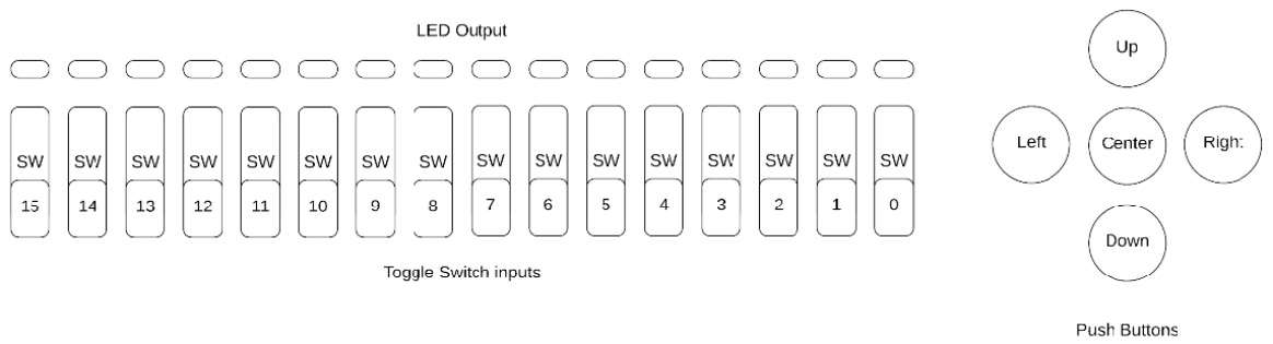
Figure 2.4 – Nexys A7 board I/O
In the previous chapter's project, we learn how to use switches for input and LEDs for output. In this project, we'll be using all the switches in the preceding diagram for the number of ones calculator and the leading-one detector. For the leading-one detector, we'll detect the position of the left-most switch that's been set out of the 16 positions.
For the arithmetic operations, we'll divide the switches into two groups. Switches 7:0 will be for input B, while switches 15:8 will be for input A. The output will be displayed as a 2's complement number using all the 16 LEDs above the switches, as shown in the preceding diagram. This means that -1 would mean all the LEDs are lit, while 0 would mean that all the LEDs are off.
Testbench
Since we will be building up individual components, we'll want a versatile testbench that will allow us to test each component individually and then all together. We'll accomplish this by using parameters. In this testbench, there are three parameters:
- SELECTOR is used for the leading-one module to determine one of four ways of finding the leading-one. It's also used to select between addition or subtraction for the add_sub module.
- UNIQUE_CASE determines whether we are going to generate unique case values or purely random numbers that can have multiple bits set.
- TESTCASE allows us to test individual components (LEADING_ONES, NUM_ONES, ADD, SUB, and MULT) or all of them (ALL).
To change these parameters in the testbench, select Settings | Simulation | Generics/Parameters:
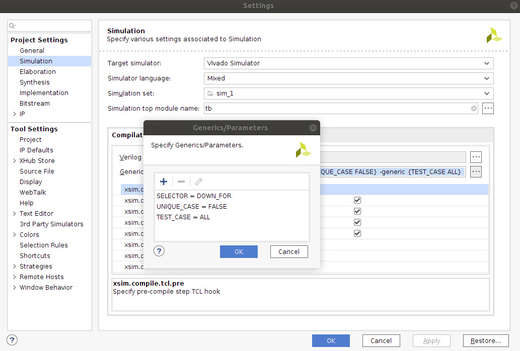
Figure 2.5 – Specifying simulation parameters
Similarly, to change the parameters for the implementation, select Settings | General | Generics/Parameters:
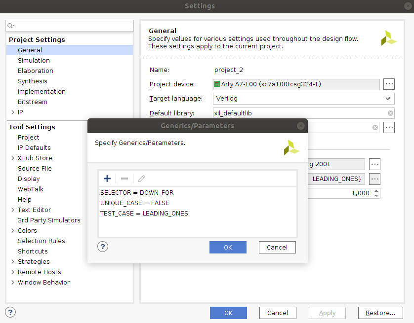
Figure 2.6 – Specifying implementation parameters
There are many ways to write testbenches. In the past, I've used separate include files for individual tests and used a shell script to invoke the simulator multiple times. If you are interested in exploring this type of testbench, please check out my open source graphics accelerator GPLGPU on GitHub: https://github.com/asicguy/gplgpu. What we will be using for our project is something simpler: using parameters to select test cases.
In general, there are three ways of testing your design.
Simulating using targeted testing
This type of test is used when you have a specific test case you want to make sure is hit. An example of this would be to see what happens when no bits are set in the leading-one detector, all bits are set in the number of ones, or the largest and smallest numbers in the case of mathematical operations. They can also be used to round out randomized testing.
Simulating using randomized testing
We are using this mostly in the self-checking testbenches that we'll be creating. To accomplish this, we'll use two system functions:
- $random(), which returns a 32-bit random number. It returns a new random number every time it's invoked.
- $urandom_range(a,b), which returns a number inclusively between a and b. In our case, we are using $urandom_range(0,4) to set one of the four buttons.
Next, we'll learn how to simulate using constrained randomization.
Simulating using constrained randomization
SystemVerilog has a very robust set of testing capabilities built into it. You can imagine this type of testing being used if you have a CPU with a number of valid instructions, and you want to randomize the testbench so that it uses these instructions and makes sure they are all used at some point. This is beyond the scope of this book, but I'll provide links in the Further reading section.
Implementing a leading-one detector using the case statement
Our first module will be a leading-one detector. We'll implement it in a few different ways and take a look at the advantages, disadvantages, and potential problems.
The first thing we need to decide is if the incoming signal is one-hot. If it is one-hot, we can get an optimized result by using the unique keyword:
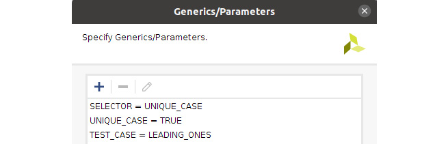
Figure 2.7 – Testing leading-one using a case statement
Verify that your simulation parameters are set as shown in the preceding screenshot.
Controlling implementation using generate
Take a moment and examine the leading_ones.sv file. Here, you'll see how a generate statement can be used to selectively create code. The format of a generate statement is generate <condition>, as follows:
generate
if (SELECTOR == "UNIQUE_CASE") begin : g_UNIQUE_CASE
In this case, the condition is an if statement, and is used to selectively instantiate one of four always blocks. Case statements and for loops are also valid conditions that we'll explore as we progress. This is where parameters are especially useful for controlling what gets created.
Tip
It is a good idea to use labels inside generate blocks. In future versions of SystemVerilog, this will be a requirement.
Notice that the case statement's default is commented out. Leave it as-is for now and run the test:
WARNING: 100000ns : none of the conditions were true for unique case from File:/home/fbruno/git/books/Learn-FPGA-Programming/CH2/hdl/leading_ones.sv:17
Why are we getting a warning? When we create a unique case, we must ensure that not only do we ever only match once, but we also match one. We want to make LED = 0 when no SW is set, so we uncomment the default. Now, we can run it again and the test will pass.
Important note
Parameters can control how logic is implemented or how testbench code is executed. In the testbench, you will see if (UNIQUE_CASE == "TRUE") begin, which controls how the code is executed to limit the number of ones being set.
Now, let's allow non-unique values to see how the simulator handles them. Change UNIQUE_CASE to "FALSE":
Setting switches to 0011010100100100
WARNING: 0ns : Multiple conditions true
condition at line:21 conflicts with condition at line:20
for unique case from File:/home/fbruno/git/books/Learn-FPGA-Programming/CH2/hdl/leading_ones.sv:17
This is only the first one that I saw, but you will see many. If our testbench hits cases that violate our unique assumption, we will see warnings that let us know the design may have problems.
So, let's see what happens when we take the design through to a bitstream by itself. Make sure that Settings | General | Top Module Name is set to leading_ones and that SELECTOR, under Generics/Parameters, is set to UNIQUE_CASE. Then, click on Generate Bitstream.
Important note
Generics/Parameters are set in two places in Vivado. General settings apply to building the design. Simulation applies only to simulation.
Take a look at the project summary. In the lower left of the window, look at the post-implementation utilization. By default, it comes up with a graph, but you can click on the table option to get hard numbers. In my build, this is what I got:
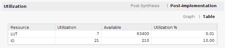
Figure 2.8 – Post-implementation utilization
We used 7 LUTs for this implementation. But what happens when we try this on the board? Open the hardware manager and the target, and then choose Program device.
We are expecting one-hot values, so try setting one bit at a time, starting from 0, so that only one switch is up at a time, one-hot encoded. Do you see the LEDs light up properly? You should see the binary value for the switch you have set plus one, so SW0 will show 5'b00001, SW1 will show 5'b00010, and SW15 will show 5'b10000. Now, try to set multiple switches, such as 15 and 0. What did you get? In my case, I saw 5'b10001. Now, try some others. You'll notice that some combinations still give the correct value by chance. There must be something to those warnings!
Now, let's try rebuilding without the unique keyword. Set SELECTOR to "CASE" and then generate the bitstream.
By looking at the summary of this build, we can see that handling priority cost us almost 2x the number of LUTs. My build took 13. Let's try it on the board.
Try combining multiple switches. Do you always get the switch position +1 for the uppermost switch?
In this section, you saw that unique allows optimization. The unique case statement was almost half the size of the case without unique. The case statement does have the disadvantage of us having to specify all possible cases, so it's not really reusable for an arbitrary number of cases. Let's explore another, more scalable way of handling a leading-one detector: using a for loop.
Designing a reusable leading-one detector using a for loop
The for loop allows us to quickly create replicated logic. In the case of a leading-one detector, it is also easy to imagine how we can do this using a for loop. There are two ways to accomplish this, both of which we'll look at in this section.
Setting SELECTOR = DOWN_FOR
The first is straightforward and follows along the lines of how the case statement accomplishes this task:
always_comb begin
LED = '0;
for (int i = $high(SW); i >= $low(SW); i--) begin
if (SW[i]) begin
LED = i + 1;
break;
end
end
end
We use the $high and $low system tasks for reusability. The loop breaks when a 1 is detected for the first time.
Tip
A break in a for loop is synthesizable. The important thing to consider is whether you can unroll the loop or if there is a way to write the loop in a way that the break isn't necessary. If you can think of a relatively easy way this can be done, then you probably won't have an issue synthesizing it.
For example, we could unroll the loop by writing it as follows:
Logic [3:0] SW;
always_comb begin
LED = '0;
if (SW[3]) LED = 4;
else if (SW[2]) LED = 3;
else if (SW[1]) LED = 2;
else if (SW[0]) LED = 1;
else LED = 0;
end
We can now look at another way of writing the for loop that satisfies our unrolling requirement.
Setting SELECTOR = UP_FOR
By progressing from the lowest bit to the highest bit while searching for a 1, we are guaranteed to find the highest bit as the last 1 that's found. This is also how you know that the break can be synthesized, since we have found a way to rewrite the for loop so that it's not necessary.
Counting the number of ones
Related to finding the leading-one is counting the number of ones in a vector. We can do this easily using a for loop:
always_comb begin
LED = '0;
for (int i = $low(SW); i <= $high(SW); i++) begin
LED += SW[i];
end
end
Set SELECTOR to NUM_ONES and TEST_CASE to NUM_ONES and run the simulation to verify it works. Verify that SELECTOR is set to NUM_ONES under the General tab and that the top module's name is set to num_ones. Then, generate the bitstream and run it on the board.
Verify the design on the board by flipping the switches one by one in any order. You should see the LEDs light up in the pattern of a binary count; that is, 16'b0, 16'b1, 16'b10, 16'b11, and so on.
Implementing an adder/subtractor
Let's take a look at the add_sub module. There are many ways to implement an adder or subractor in math in general. Many companies sell tools for high performance or low gate count designs. For FPGAs, 99% of the time, you are better off letting the tools optimize your designs. Because of this, you'll see that the module itself is fairly small. We choose whether we are adding or subtracting based on the SELECTOR parameter.
Add
Set SELECTOR to ADD and TEST_CASE to ADD and run the simulation to verify it works. Verify that SELECTOR is set to ADD under the General tab and that the top module's name is set to add_sub. Then, generate the bitstream and run it on the board:

Figure 2.9 – Top module set to add_sub
Once you've downloaded the bitstream on the board, try some combinations of bits on the lower 8 and upper 8 bits. In particular, if you set bit 0 and bit 8 both to 1, you should see bit 1 set on the LED; that is, a value of 16'h2. Now, try setting bit 0 and bit 15 – what do you get?
It may look a bit weird seeing so many LEDs lit, but you'll notice that only the upper bits are lit. This is because we have specified 8'h80 + 8'h1. Since we are specifying two's complement numbers, in decimal, this would be -128 + 1 or -127, which in hex would be 16'hFF81.
Subtractor
Set SELECTOR to SUB and TEST_CASE to SUB and run the simulation to verify it works. Verify that SELECTOR is set to SUB under the General tab and that the top module's name is set to add_sub. Then, generate the bitstream and run it on the board.
Now, we are subtracting the lower 8 bits from the upper 8 bits. Try setting bit to 0. All the LEDs should be lit, or -1.
Important note
Remember, to get -1 in binary, we invert and add 1; for example, -16'b0000000000000001 = 16'b1111111111111110 + 1 = 16'b1111111111111111.
Note that for the adder and subtractor, no matter what you add with signed numbers, the upper 8 bits will always be either all 0s or all 1s.
Multiplier
The final module we will look at is the multiplier. HDL is the simplest out of all of them, and since the multiplier is only 8*8, by default, it is implemented in LUTs.
Set SELECTOR to MULT and TEST_CASE to MULT and run the simulation to verify it works.
This simulation is automated. However, we can also use the add_force command in the simulator. An example of this is shown in the following screenshot. A force will override a value on a signal in the simulator. When the simulation ended, I forced a value of 0x1234 onto the SW input of the multiplier. Since I've done this, I need to advance simulation time, which I can do with run 10ns.
The force command is good for when you are trying to isolate a particular scenario or experiment with a what if scenario during a run. In general, you will not want to simulate solely this way as you'll want to have a way of reproducing your results, so putting your tests in a SystemVerilog testbench is a better long-term solution.
If and when you are done with a scenario, you can use the remove_forces command on a signal to return control to the testbench:
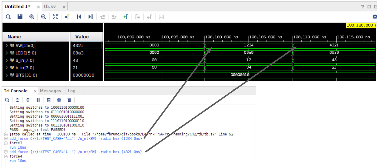
Figure 2.10 – Force statement in a simulation
Verify that SELECTOR is set to MULT under the General tab and the top module name is set to mult then generate the bitstream and run it on the board:
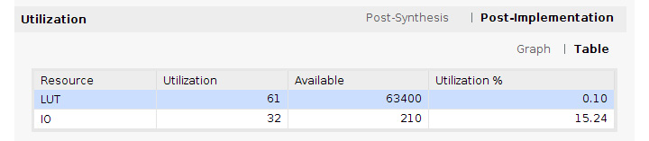
Figure 2.11 – Multiplier utilization
The preceding snippet shows our utilization from building the multiplier.
Tip
Adding two signed numbers of size n will result in a value of size n.Adding two unsigned numbers of size n will result in a value of size n+1.Multiplying two numbers of size n will result in a value of size 2*n.
Bringing it all together
Now, we'll create a simple ALU top level so that we can bring everything together. Take a look at project_2. There are five buttons on the board. We'll use these to control the output:

Instantiate the submodules. We'll need to use add_sub twice and use SELECTOR so that it's hardcoded to select the one we want. We'll still pass the selector to the leading-one calculator in case we want to play around with it:
leading_ones #(.SELECTOR(SELECTOR), .BITS(BITS))
u_lo (.*, .LED(LO_LED));
add_sub #(.SELECTOR("ADD"), .BITS(BITS))
u_ad (.*, .LED(AD_LED));
add_sub #(.SELECTOR("SUB"), .BITS(BITS))
u_sb (.*, .LED(SB_LED));
num_ones #( .BITS(BITS))
u_no (.*, .LED(NO_LED));
mult #( .BITS(BITS))
u_mt (.*, .LED(MULT_LED));
Now that we have overridden the names of the LED outputs of the submodules, we can mux them to the LEDs:
always_comb begin
LED = '0;
case (1'b1)
BTNC: LED = MULT_LED;
BTNU: LED = LO_LED;
BTND: LED = NO_LED;
BTNL: LED = AD_LED;
BTNR: LED = SB_LED;
endcase
end
Set TEST_CASE to ALL and run the simulation to verify it works. Verify that SELECTOR is set to UNIQUE_CASE, CASE, UP_FOR, or DOWN_FOR under the General tab and that the top module's name is set to project_2. Then, generate the bitstream and run it on the board:
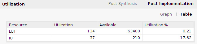
Figure 2.12 – Complete project_2 utilization
When the image finishes downloading, the LEDs will be off. Flip some switches and select a function by pushing a button. Congratulations – your simple calculator is complete! Notice that when you release the button, the LEDs go dark.
Adding a latch
Since we are not using any clocks yet, let's add a latch. In this particular case, the switches are static, so using a latch shouldn't cause us any problems:
always_latch begin
//always_comb begin
//LED = '0;
Change always_comb to always_latch and comment out the LED = '0; default. Then, rerun it. What happens when you download and try to select an operation? If your build is like mine, then this operation will not be what you expected and the LEDs will seem to behave in an almost random fashion. This is the reason that I have stressed not to use latches. If you encounter a situation where your circuit doesn't behave as intended, search the compile logs and make sure no latch is inferred.
Summary
In this chapter, we learned how to create combinational logic, how to create different modules, and how to test them as utilize self-checking testbenches. We also explored different optimizations we can perform on the case statement and showed you how to get substantial area savings in some cases, but also how we may have problems if our design assumptions are incorrect. We then mentioned latches and the problems they cause, even when they should be safe.
At this point, hopefully, you have some confidence in how to create logic and test it. In the next chapter, we'll introduce sequential logic; that is, using registers to store values and perform operations. We'll expand upon our simple calculator and see how we can improve it now that we have some storage elements.
Questions
- A packed array is used to infer memories. True or false?
- A break statement can be used in a for loop when?
a) Any time.
b) If it's possible to rewrite the for loop in such a way as to not need the break.
c) Only if you can reverse the direction of the loop; that is, go from low to high instead of high to low.
- Size the add_unsigned, add_signed, and mult signals:
Logic unsigned [7:0] a_unsigned;
logic unsigned [7:0] b_unsigned;
logic signed [7:0] a_signed;
logic signed [7:0] b_signed;
assign add_unsigned = a_unsigned + b_unsigned;
assign add_signed = a_signed + b_signed;
assign mult = a_unsigned * b_unsigned;
- Division is a very costly operation. Look at the supported Vivado constructs in the Vivado Synthesis manual (Further reading). Can you easily replace the multiply operation with a division operation? What is possible without custom code?
Challenge
Look at the following add_sub module:
logic signed [BITS/2-1:0] a_in;
logic signed [BITS/2-1:0] b_in;
…
{a_in, b_in} = SW;
If you were to replace a_in and b_in with a custom type that encapsulates both, would you use a structure or a union? Modify the code so that it uses your custom type, and then simulate and try it on the board.
Further reading
Please refer to the following links for more information regarding what was covered in this chapter:
- UVM information: https://www.accellera.org/downloads/standards/uvm
- Vivado Synthesis manual: https://www.xilinx.com/support/documentation/sw_manuals/xilinx2020_1/ug901-vivado-synthesis.pdf