Chapter 5
Other Network Standards
Abstract
This chapter presents several standards that may be incorporated into certain passive optical networks (PONs), depending on what you plan to do with the PON. This is often based on the services you will offer, your present business(es) and your competitive landscape.
Keywords
Active Ethernet; DOCSIS; DPoE; EPoC; MEF; Metro Ethernet Forum; ODN; Optical distribution network; Oversubscription; P2P; Point-to-point; R-ONU; RFoG; Service-level agreements; SIEPON; SLA
Introduction
Besides the EPON and GPON standards, there are other fiber-to-the-home (FTTH) standards that we should mention. Some are standalone standards in their own right, others are really supplementary standards intended to enhance other standards, or to be bridge standards, where the end game is GPON or EPON, but for various reasons, the operator is not prepared to make that leap yet. We present them so that you will understand what people are talking about when they mention them, and so that you can make a decision regarding incorporating them into your plant.
Point-to-Point Systems
Point-to-point (P2P), or Active Ethernet (AE), is an alternative to EPON and GPON, installed by some operators. A single home-run fiber is installed from the headend to each customer. Because there are no splitting losses to account for, optical signal levels can be quite low. Standards to support P2P were codified in the original IEEE 802.3ah standard, now part of the 802.3 Ethernet standard. In a P2P system, each subscriber has a dedicated Ethernet port in the headend, a dedicated fiber to his home or business, and a dedicated optical network terminal (ONT) at the home (as always). As shown below, it is not really feasible to carry broadcast video on a P2P network: most operators carry IPTV if they carry a video service, though we have seen a very few operators actually build a parallel HFC or PON network to deliver video.
P2P Architecture
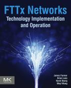
Fig. 5.1 illustrates a P2P architecture (as distinguished from a PON architecture). One or (usually) more P2P switches, which include the fiber interfaces on the subscriber side, connect to individual subscribers, using a 1550-nm downstream data carrier and a 1310-nm upstream data carrier (as we shall show shortly, it is not really feasible to use broadcast video with a P2P system, so using 1550 nm for data is not a problem).
The P2P switches are connected to the headend (or hub) primary data switch, typically using multiple 1 Gb/s or 10 Gb/s (preferred) Ethernet links, which may be either electrical or optical. The primary data switch connects to all of the auxiliary servers needed, to the Internet, and to the IPTV headend. There may be other servers used that are not shown. For example, some of the IP video service providers [they are called over-the-top (OTT) providers, because they provide video outside of the operator’s video service] may place servers in the headend of a large system. The reason is so that popular OTT programs can be buffered locally, relieving the data burden (and cost) of the Internet connection, and providing better service because you don’t have to worry about Internet congestion.
Data Concentration in P2P Networks
An advantage often cited for P2P networks over PONs is that you don’t have the shared data path you do in PONs, so you can get a full Gb/s (or whatever) data speed to each subscriber. Well, yes and no, but mainly no. Fig. 5.1 shows why. Suppose I have a small system with just the two P2P switches shown. A typical number of subscribers served from one switch chassis might be 144 subscribers. If each were to get 1 Gb/s, then the total data bandwidth required by the chassis is 144 Gb/s. While it is possible, we have rarely if ever seen a chassis connected to the headend switch by more than two 10 Gb/s data links. If the two links could each be utilized to 100% capacity (impractical in the real world), then the maximum average data rate you have to provide to each subscriber at this point, is really 20 Gb/s divided by 144 subscribers, or 140 Mb/s, a far cry from the 1 Gb/s assumed.
But it gets worse! Now figure in the two chasses, serving a total of 288 subscribers (not really a big enough system to be practical). OK, so each subscriber really uses an average of 140 Mb/s to the headend switch. But for economic reasons, you are not too likely in a small system to have more than 1 Gb/s to the Internet, and even this is likely to be cost-prohibitive for a small system. But if I have 288 subscribers sharing a 1 Gb/s link to the Internet, then I really have 1 Gb/s divided by 288 subscribers, or just under 3.5 Mb/s on the average for each subscriber, not the 1 Gb/s assumed.
Case in Which P2P May Have an Advantage Over PON
There may be some advantage in a P2P network over a PON if you do find you need more speed for a few subscribers. With P2P networks, you can change out terminal equipment for one customer needing more speed. Both the GPON and EPON standards claim seamless upgrade to the next generation, though doing so may require a larger investment for the first customer who wants more speed. Also, if you were to design for a certain speed in the PON and later found you needed more, you would need to change the entire PON termination equipment (but not the fiber). With P2P, you could simply add more data capacity on the network side of the P2P switch.
Case in Which P2P May Have a Disadvantage Over PON
It is hard to imagine a P2P system being installed for the same cost as a PON. And while the operational expense (op ex) is definitely going to be less than for copper or coax plant, it is hard to imagine P2P op ex being as low as is that for PON. There is a good bit more fiber needed for P2P than for PON, and while the cost of the fiber itself is not that great, and the installation cost is arguably similar in both cases, there will be a much higher splicing cost with P2P; typically you leave the headend with a few large bundles (cables) of fiber strands. Along the way, the fibers diverge, and when they do, you will need to splice each fiber strand to one in a smaller cable. This can result in a larger, much larger, number of fiber splices with P2P, each splice being rather labor-intensive.
Finally, the larger numbers of fibers leaving the headend can produce quite a headache in the case of a backhoe fade (any cable break). If the cable break occurs in most of the plant, you will have about 32 times the number of splices to make with P2P. Cable breaks seem to have a tendency to occur in the most difficult locations, at the most difficult times, increasing the cost and delay of service restoration.
Oversubscription
For residential service, this is not nearly as bad as it seems, and now we shall see why the Internet works at all, the magic being oversubscription. First, we have not taken into account that some people are using some of their data bandwidth for video, and this does not take away from the Internet bandwidth as we have defined it (but see the Chapter 12 on IPTV for a lot of “gotchas” with IPTV service). Also, no residential subscriber is using his Internet bandwidth continuously, and when one subscriber is NOT using it, the protocols used make that bandwidth available to other subscribers. This bandwidth sharing is what makes the Internet so efficient. A subscriber may pull down a web page, and he is using his bandwidth in the process. But then he may spend 5 minutes on that web page, during which time he is not using any bandwidth.
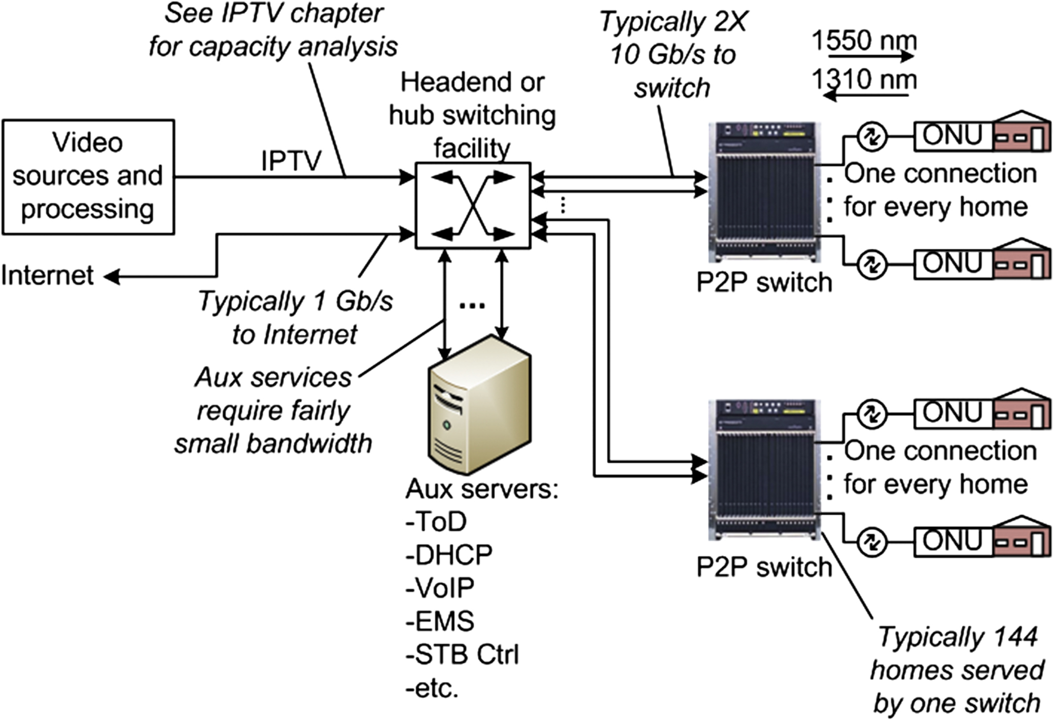
We can illustrate the power of statistics very nicely with a totally unrealistic picture of an unrealistic situation depicted in Fig. 5.2. What we have done is to assume that each subscriber in the system of Fig. 5.1 is using either 100% or none of his allowed bandwidth during any arbitrary time period. We have further assumed that the probability of any one subscriber using his bandwidth during any one time period is 10%—unrealistically high except maybe for some video applications. We have let a random number generator go through a lot of cases and we have totaled up the bandwidth used as a percentage of the bandwidth that would be available if we added up everyone’s allowed bandwidth.
If we do this experiment with only one user, we see that he is using all of his bandwidth, but for only about 10% of the time, not surprising since these are the parameters we programmed into the simulation. So if we are going to give this subscriber the bandwidth we promised, we have to provide the capability of that bandwidth. Seems logical.
But now let’s look at the situation in which we have 25 subscribers sharing the total bandwidth we promised them. Do we really need to provide 25 times the bandwidth in order for each subscriber to get what we promised? No, not according to this simulation. We never even used 30% of the bandwidth—that’s the power of statistics. Not everyone is going to be using all of their bandwidth at the same time, so sharing works well. Keep the logic going, and let’s total up all 288 subscribers doing the same unrealistic thing, each using 100% of his bandwidth but only 10% of the time. We can satisfy this need while providing only 15% of the promised bandwidth—statistics are working really well in our favor!
Now remember that this is hardly a real-world simulation. Not every subscriber is going to demand 100% of his bandwidth 10% of the time. The real-world is infinitely more complicated than this, with one subscriber pulling significant bandwidth while another reads a book, another grabs a snack, and another works on his car. ISPs like to keep such statistics to themselves, but some casual conversations in the past have indicated that you could oversubscribe about 30 times without anyone complaining. That is, if you have 30 Mb/s total bandwidth available (not an FTTH number, but we got this from cable TV a while ago), you can sell subscribers bandwidth totaling 30 times this, or 900 Mb/s without subscribers noticing any problems. Of course, you cannot sell any one subscriber more than 30 Mb/s, since that would hit the maximum available.
These numbers may be changing, though, as subscribers pull more OTT video, which may not conform to the old norms. Those old norms involved mostly pulling down web pages and email. So we can’t guarantee the same numbers in the future. The bottom line is that you may not be able to oversubscribe as much in the future, but only time and monitoring bandwidth usage will tell you for sure.
Business Services
So far we’ve talked about residential service. Business services, now that’s another matter. You may well have service-level agreements (SLAs), with businesses, which do require you to provide constant connectivity for the business, and you will be tested to see that you are delivering. This bandwidth can be shared with residential so long as you have enough residential bandwidth after you deduct that which you are selling to business customers under SLAs. Then you will need a mechanism to prioritize bandwidth, so that businesses get what they contract for before you start doling out the remaining bandwidth to residential customers, who can share. Fortunately the protocols needed to get this done exist, and we’ll get around to them in later chapters.
RF Over Glass (RFoG)
The cable TV industry has defined and is installing in some places, an FTTH architecture with the most fun acronym we have ever encountered: or RF over glass (RFoG). RFoG uses an identical physical architecture to EPON or GPON, and many people see it as an interim step in moving to one of those standards. Rather than use downstream binary data at 1490 nm and upstream binary data at 1310 nm, with a 1550-nm broadcast overlay, as do other PON standards, RFoG places a downstream carrier modulated with many radio frequency (RF) carriers, on 1550 nm. It places upstream data, modulated onto RF carriers which are then modulated onto either 1310 nm or 1610 nm. The reason for two upstream wavelengths is that some operators want to keep cost down by using more common 1310-nm lasers, at the expense of compatibility with EPON or GPON. Other operators, anticipating eventual conversion to EPON or GPON, elect to put the upstream signals on 1610 nm, which is not used by the other standards.
The advantage of RFoG for a cable operator is that it allows using termination equipment which is already being used, and with which the employees are familiar. The video service comprises a large number of RF carriers, each either modulated with one analog video channel, or more commonly, modulated with several digital signals. Downstream data use some of those RF channels, with the modulation being produced by a DOCSIS CMTS [DOCSIS defines a series of standards for transmission of data on cable TV systems, and a CMTS (cable modem termination system) is the headend equipment supporting DOCSIS modems]. The upstream data come from each home, and are generated either by a DOCSIS modem or by a set top box, which must have an RF transmitter in order to transmit control data back to the headend.
RFoG System Block Diagram
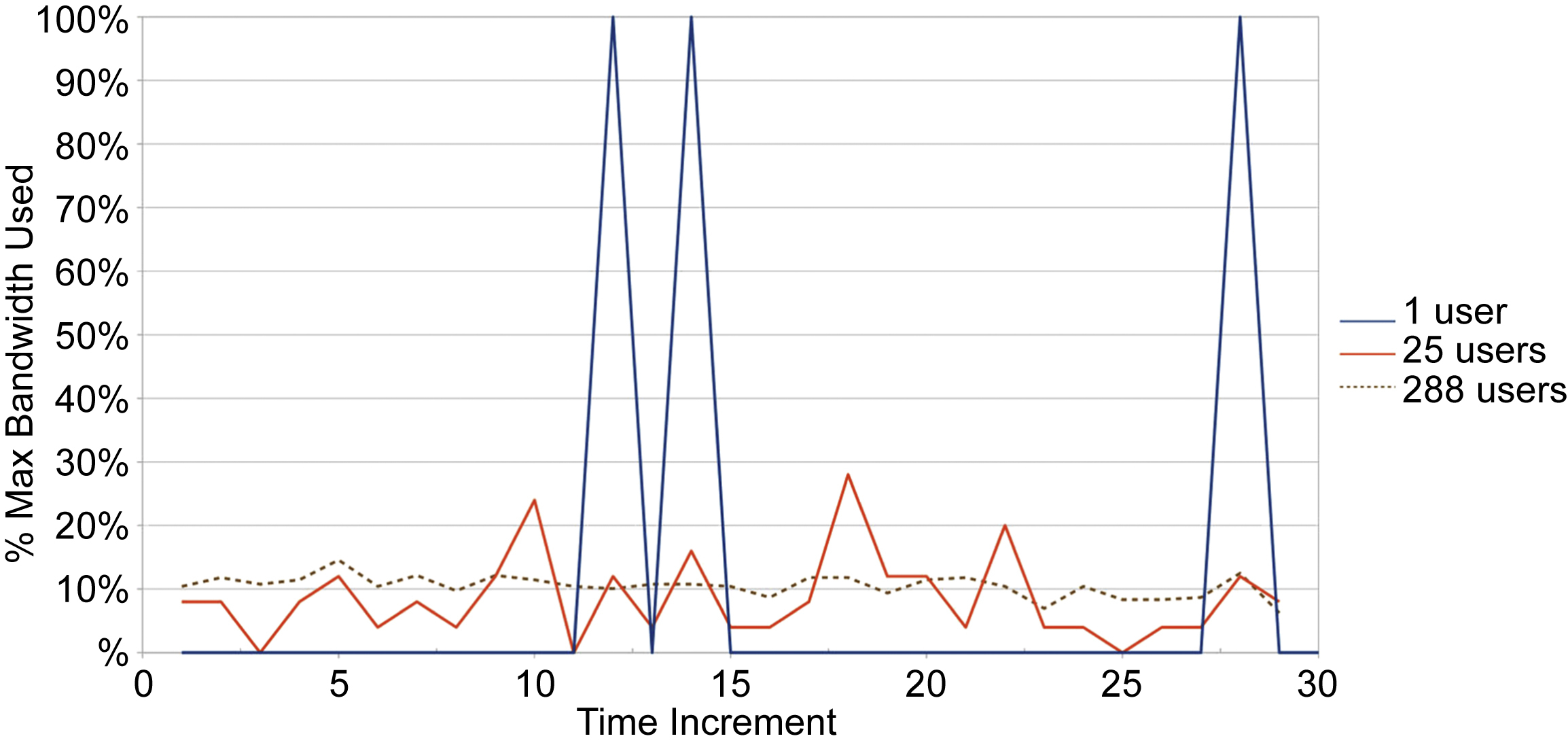
Fig. 5.3 illustrates the block diagram of the RFoG system.i To the left is the optical hub or the headend, depending on the physical architecture of the system. It includes one or more downstream optical transmitters putting out a signal at approximately 1550 nm. It is amplified in an optical amplifier and split according to the number of PONs needed. In some cases there may be more than one downstream optical transmitter. Each output of the splitter is supplied to a wave division multiplexer (WDM), which separates the 1550-nm downstream from either the 1310- or 1610-nm upstream transmissions, depending upon which wavelength the system is using. The upstream wavelength goes to an upstream optical receiver, whose output is the RF signal as it entered each R-ONU, as shown below. The output of the receiver will go to the CMTS and likely also to a set top control system.
The optical distribution network (ODN) is identical to that of an EPON or GPON system, including the 32-way or 64-way splitter. As always, the splitter may be located in one place as in the diagram, or splitting may be distributed in any way the operator sees fit, so long as the total loss budget is respected. The standard recommends a loss budget of 25 dB if analog signals are present, with more loss being tolerable if all digital signals are being transmitted. The standard also refers to other situations in which you might be able to operate with a little more loss. However, the EPON standard is written around a 25-dB loss budget (though more loss is usually practical), so if one contemplates upgrading to EPON in the future, this specification limitation must be taken into account.
The subscriber-facing side of the R-ONU (RFoG ONU, so named to distinguish it from an EPON or GPON ONT) looks just like a normal cable TV system terminating on coax at the subscriber’s home. The downstream signals appear every 6 MHz starting at 54 MHz (North American standard—different frequencies are used elsewhere). The maximum frequency usually specified today is 1 GHz, though not all systems may be using frequencies that high; even higher frequencies may be used in the future. Any signal may be modulated with one analog TV channel, multiple digital TV channels, or data (including voice data). Control signals sent with the digital TV channels or on a separate RF carrier tell the set top what frequency to tune and what channel to display. For digital TV, additional information tells the set top where to find data packets for each of the several TV signals in the channel to which it is to tune. The old paradigm of a one-to-one correspondence between channel number and frequency is still used internally to describe the frequency plan, but is of little to no relevance today for the subscriber, as the set top may be told to display any channel number for any frequency.
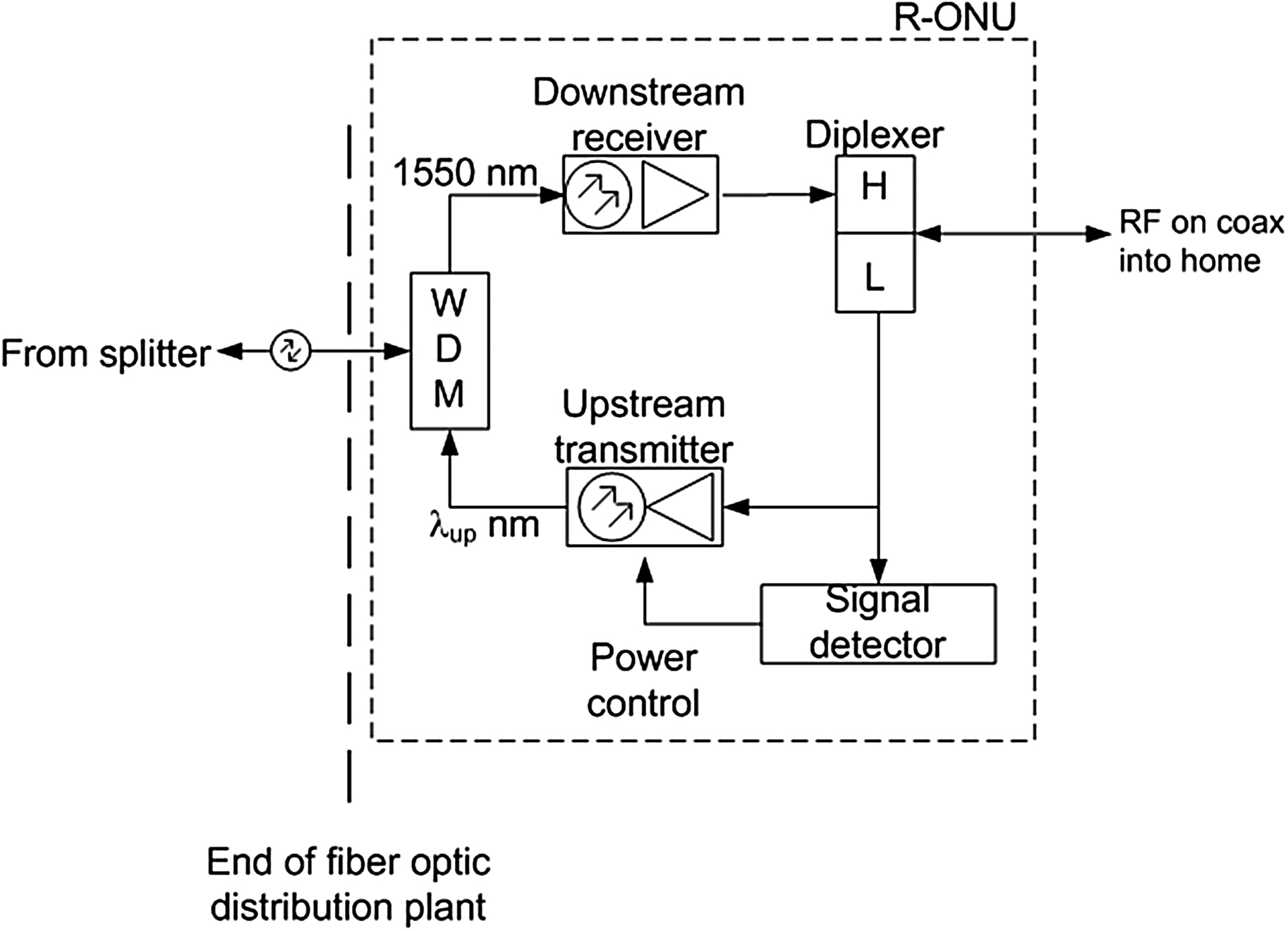
The R-ONU
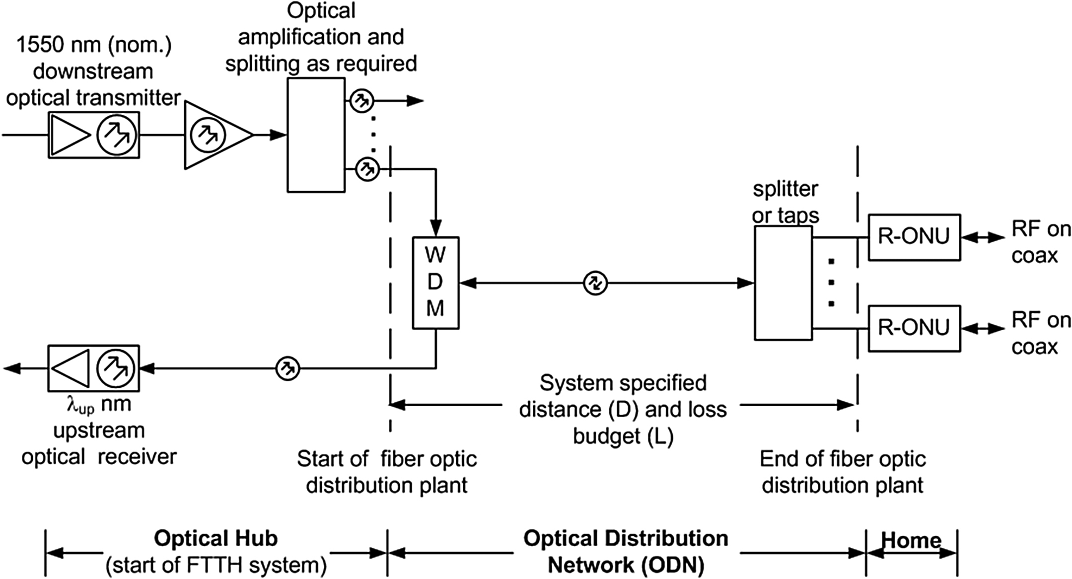
Fig. 5.4 illustrates the R-ONU. At the fiber side, coming from the splitter, the first device encountered is a WDM which functions identically to the one at the headend (Fig. 5.3), by separating the downstream and upstream signals. The 1550-nm downstream signal goes to the downstream receiver, which has some form of automatic gain control (not shown) to compensate for changes in the received optical level. Its output goes to a diplexer, which functions in the RF domain as does the WDM in the optical domain. By that we mean that it separates and routes the higher-frequency downstream signals (54–1000 MHz in North America) and the lower-frequency upstream signals (5–42 MHz in North America) sending them where they should go.
The upstream signals are routed to the upstream transmitter, and also to a signal detector circuit. The purpose of the signal detector is to determine when an upstream signal is present at the RF port on this R-ONU, and to turn on the transmitter. This is necessary because each R-ONU has its own upstream optical transmitter, and if all were on at the same time, a lot of interference would result.
DOCSIS Provisioning Over EPON (DPoE)
In the late 1990s, the cable TV industry began the deployment of broadband services using a standards-based architecture called DOCSIS, as mentioned in the previous section. The DOCSIS architecture defined two network elements beginning with the cable modem termination system (CMTS) at the headend and the cable modem (CM) located within the subscribers’ premises. This standard was developed by CableLabs then sent to the Society of Cable Telecommunications Engineers (SCTE) to provide the formal development of the standard. Over the following decades CableLabs continued the development of the DOCSIS standards to include QoS, Voice, and high-bandwidth services.
As DOCSIS gained in popularity, becoming the primary technology for the deployment of voice and high-speed data services in North America and elsewhere, CableLabs continued to expand the operational aspects of the protocol to include operation, administration, and maintenance (OAM) features, security, operational support system extensions, and other features. Eventually, the cable TV industry found itself managing millions of cable modems globally, supported by a complete industry of hardware and software vendors.
As the cable TV industry began considerations for FTTH technologies beyond RFoG, CableLabs commenced the development of a new standards-based architecture. With participation from the vendor and operator communities, CableLabs defined the DPoE specifications.
CableLabs made the selection of EPON based on feedback from the participating operators leaning toward 1G-EPON and 10G-EPON technology. During the initial drafts of the DPoE specifications, 10G-EPON had already been standardized, supporting symmetrical 10G services while being backward compatible with 1G-EPON technology. The vendor community was in the infant stages of producing 10G-EPON equipment, making EPON the logical approach for the cable TV industry to standardize. As this is written, there is talk about doing the same for GPON.
Common Provisioning, Management, and Services
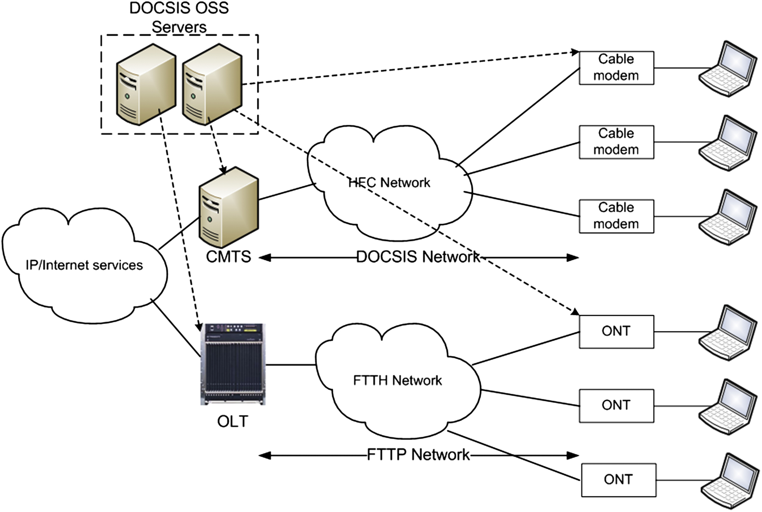
A network supporting DPoE service models such as IP HSD (high-speed data) or MEF (business-related standards promulgated by the Metro Ethernet Forum) operate correspondingly to a similar DOCSIS network. Within the DPoE architecture the OLT is analogous to a CMTS and the DPoE optical network unit (ONU) operates like a DOCSIS cable modem. The same back office servers should be capable of managing both the DOCSIS and DPoE system concurrently using the same standards-based cable modem configuration files. Fig. 5.5 illustrates DPoE and cable modems under a common management umbrella.
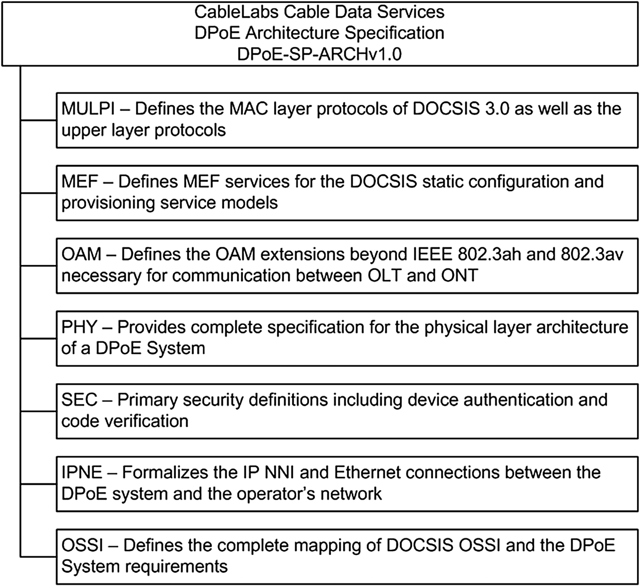
The initial specifications for the DPoE v1.0 standard process consisted of seven different specifications. These specifications defined the complete operational and management interfaces. Fig. 5.6 provides an overview of each specification.
OLT/ONT Interoperability
In addition to defining a cable TV operational model within an EPON environment, CableLabs took on another challenge to ensure the interoperability between OLT and ONT devices from different suppliers. Historically, when defining the initial 802.3ah specification (the original EPON specification), the IEEE did not provide an OAM&P (operations, administration, maintenance, and provisioning) context to support end-to-end service provisioning between the UNI of the ONT and the NNI of the OLT.
Up to this point, the cable TV industry was not constrained by such lack of interoperability within the vendor community. Operators were free to choose CableLabs qualified equipment, guaranteeing complete interoperability and integration within their DOCSIS network. In order for the deployment of EPON technology using DPoE to be successful, CableLabs had to address this deficiency of EPON (the deficiency being lack of a defined OAM&P), not only defining the necessary interfaces but also a process to qualify vendors.
Using similar processes in place to guarantee CMTS and CM interoperability, CableLabs has established a complete interoperability program for vendor community participation. CableLabs hosts multiple “certification waves” throughout the year where vendor OLT and ONT equipment are qualified. The cert waves (as they are called) are handled independently by CableLabs without vendor participation.
EPON Protocol Over Coax (EPoC)
In 2011 a group of operators in China, joined by North American operators, saw a market requirement for the development of a standard to extend the IEEE 802.3ah point-to-multipoint architecture to operate over a coax-based PHY (physical) layer. The goal of this community was to deliver the same scheduling, management and quality of service (QoS) models to operate the same way regardless of an optical or coax connection to the subscriber. A call for interest (CFI) was initiated during this period with interest from all areas of the cable industry including global operators, chipset vendors, and system vendors, with Broadcom taking the lead role. The formation of the EPoC Task Force was chartered by the IEEE 802.3 Working Group as the IEEE 802.3bn Task Force.
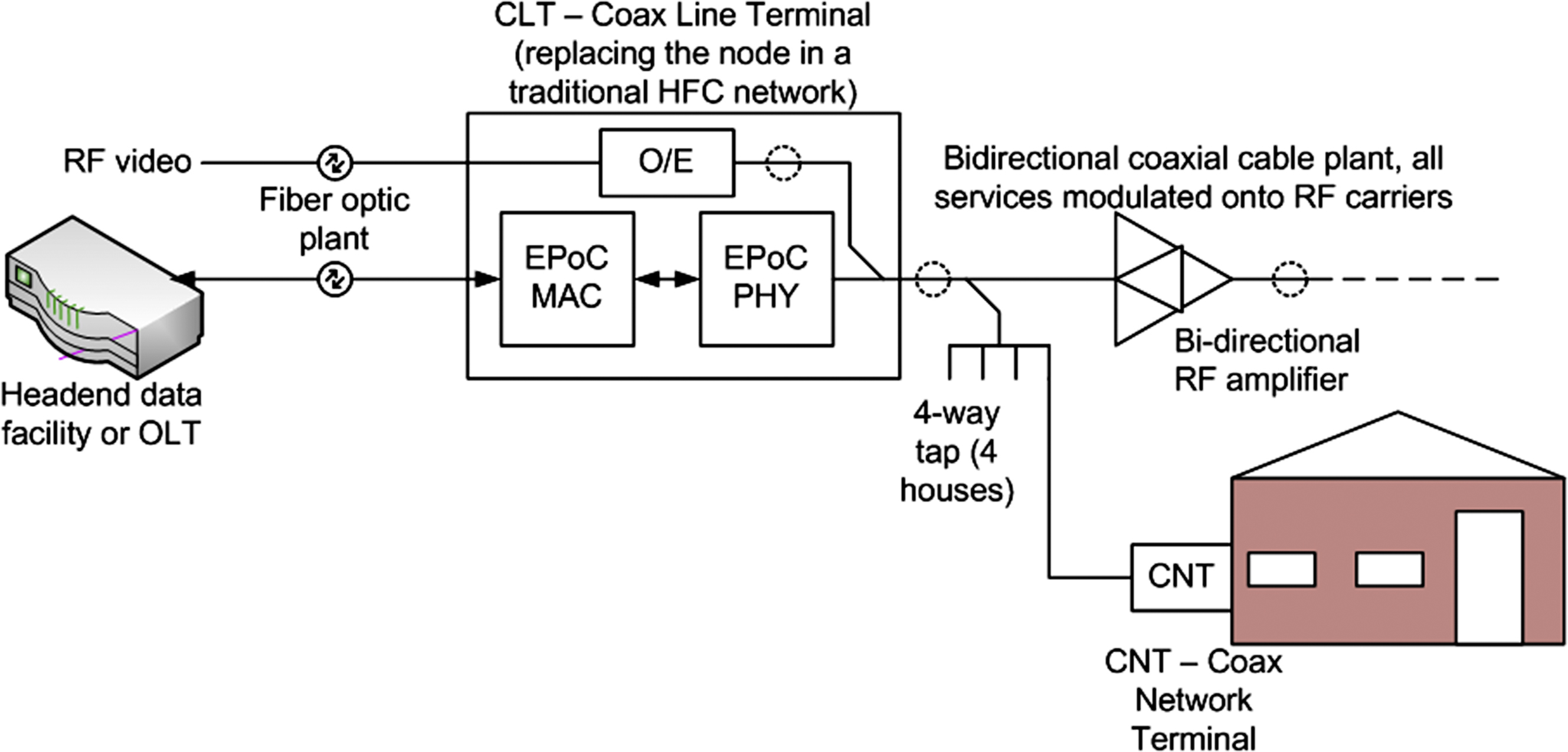
Fig. 5.7 shows the concept of EPoC. Where the node goes in a traditional HFC plant, we substitute the CLT. The CLT accepts the same inputs as would be supplied to an OLT in a conventional FTTH system, or an output of an OLT may drive the CLT. The CLT converts all signals to RF modulation, required in the coaxial cable plant, and modifies the EPON protocol to work in this environment. Signals are coupled to homes via in-place coax plant, and terminate in a CNT at each home.
The high-level architecture of an EPoC network is consistent with its big brother, EPON. In an EPON network, the MAC and PHY layer located in the hub site is termed an optical line terminal (OLT). Within an EPoC network the node is exchanged with a coax line terminal (CLT). Similarly, the MAC and PHY layer located at the residence or subscriber location is termed a coax network terminal (CNT) rather than an optical network terminal (ONT). The term coax network unit may be substituted for coax network terminal. In a PON, the communication channel between the OLT and ONT is an optical network allowing for multiple ONTs to be connected to a single PON interface on the OLT, while in an EPoC network the coax portion of the communication channel allows multiple CNTs to be connected to a single interface on the CLT.
The physical layer in the coax network conforms as much as possible to the physical layer in DOCSIS 3.1. DOCSIS 3.1 adds OFDM (orthogonal frequency division multiplexing) to the QAM modes used in earlier versions of DOCSIS. It also has the ability to bond many channels in order to achieve higher overall data rates. At the same time, it provides the ability to vacate channels when there are conflicts with off-air use of those channels.
Current Status
The standardization work is being done by the IEEE 802.3bn task force. Their result of the PHY standard will allow for multiple deployment models as well as an objective for a migration path toward 10 Gbit/s. The deployment models could be characterized as a single deployment model of a standalone EPoC system or an EPoC system operating as an extension to an EPON network with a single deployment and services model in place.
As this is written, EPoC is in the early stages of balloting in the IEEE process, with the intent that it will become an amendment to the 802.3 Ethernet standard. After that, the market will take over and determine how EPoC fits into the solutions available to the operator.
Service Interoperability in Ethernet Passive Optical Networks (SIEPON)
In 2009 a group of industry vendors focused on extending the capabilities of the IEEE 802.3ah EPoN specifications formed a working group under the sponsorship of the IEEE. The objective of the working group was the development of a standard to allow for service-level interoperability among EPON and future 10G EPON vendors. Prior to the working group focus, the EPON and 10G EPON standards focus was on the interoperability at the physical layer and data link layer between the OLT and ONT. This was great if you just needed two pieces of network equipment to communicate with each other. Not so good if someone is trying to access the Internet, make a phone call, or even watch TV. Communication at higher service and QoS/CoS levels was more-or-less the wild wild west. Every vendor had their unique “theory of operation,” making interoperability at the service level a challenge at best.
Hence, the SIEPON working group was formed, entitling their efforts the Service Interoperability in Ethernet Passive Optical Networks (SIEPON). Rather than pronounce the acronym, it is usually spelled out in speech. The working group focused on the development of a standards-based architecture for EPON devices to follow with two purposes: (1) open competition of suppliers of OLT and ONT equipment and (2) drive innovation and price reductions within the EPON community through direct competition. The SIEPON organization was not intended to become a certification authority, but rather would define the specifications by which the vendor community may abide, with other possible organizations to certify compliance.
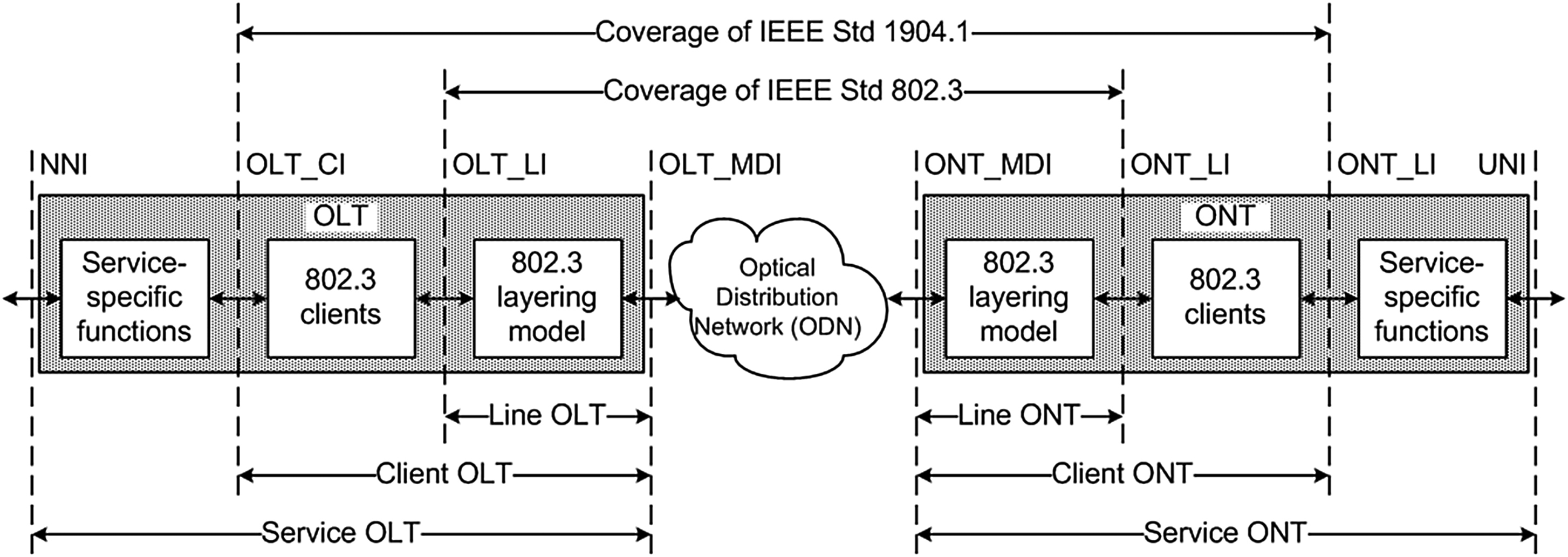
The IEEE SIEPON working group drafted a standard in September 2011, with the first official standard published in September 2013 as IEEE Standard 1904.1-2013. The standard defined an operational and management architecture layered above IEEE 802.3 and 802.1 without impacting higher-level service protocols necessary for end-to-end communications. Fig. 5.8 shows the level of coverage the IEEE 1904.1-2013 standard supports.
One of the primary strengths of SIEPON was allowing for coexistence of existing and upcoming networking models within the access community. Existing DSL/G.PON-driven standards from the Broadband Forum and ITU-T, namely TR-200 and SG15/Q2, were still able to coexist in an environment with SIEPON. Furthermore, the development of the DPoE specification by CableLabs allowed for the DPoE Service OAM Specification (DPoE-SP-SOAM) to extend SIEPON as the basis for its development.
Current Status
Within the SIEPON specifications a series of three packages were defined based on different deployment models. Package A was assigned to those services associated with North American operators. Package B was assigned to those services associated with Japanese operators and Package C was assigned to Chinese operators. Currently the SIEPON working group is focused on the definition of conformance test procedures for each package.
Once the Annexes are completed, under the direction of the IEEE Conformity Assessment Program, the SIEPON Conformity Assessment Steering Group will develop a “testing and certification program” to be executed by independent and authorized test facilities.
..................Content has been hidden....................
You can't read the all page of ebook, please click here login for view all page.