Chapter 14
Network Management Architecture and Design
Abstract
The key accessory required for an fiber-to-the-home (FTTH) deployment is a network management platform capable of integrating all management elements into a simple, easy to use and flexible system. Furthermore, this must be integrated into a system which can reliably manage the deployment of services and billing to them accurately. This chapter provides visibility into the management of an FTTH deployment and the services which are provided to the customer.
Keywords
BSS; CLI; Configuration; EMS; ITU; MIB; Network management; NMS; OAM; OSS; OTDR; Performance management; Provisioning; RFC; SNMP; SOAP; SSH; Telnet; X.700; XML
Network Management Architecture
As long as there have been telecommunication systems providing services to residential and enterprise subscribers there have been management systems. These telecommunication systems have become more sophisticated today, with multiple heterogeneous platforms each with their own independent element management system (EMS). Operators have been forced to move from simple command line interface (CLI) management interfaces to large-scale distributed platforms providing a common view across each EMS platform. The expectation of the higher-level management platform is to provide a common solution for monitoring, maintaining, and monetizing an operator’s network.
In the early 1990s the International Telecommunications Union (ITU) defined a series of standards beginning with X.700, titled “Management Framework for Open Systems Interconnection (OSI) for CCITT Applications”. X.700 formalized a structure of network terminology and framework for the management of these heterogeneous platforms. The OSI management framework was defined into five functional areas including (1) fault management, (2) configuration management, (3) accounting management, (4) performance management, and (5) security management. In addition to the five functional areas, as fiber-based access networks start to offer subscriber-facing services, the capability of an FTTx management system to perform troubleshooting and routine or on-demand maintenance becomes more and more useful. Therefore we have decided to extend the framework for the purposes of this book to include a sixth functional area, troubleshooting and maintenance.
More recently the Broadband Forum (BBF)i has started the effort to address the management architecture and operational process requirements for PON-based network deployments. Many concepts thereof have been derived from the copper digital subscriber line (DSL) access network (see Fig. 14.1) that has existed since the 1980s. Included in these efforts is extending the management architecture to include a further functional area of service quality monitoring (in addition to providing additional structure around configuration management and fault management).ii This chapter provides details on each of these functional areas.

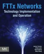
We have done our best to make sure the terms EMS and network management system (NMS) are not used interchangeably. As we use the term EMS, we are indicating a system or toolset whose responsibility within the network management system is to manage a single autonomous system. Examples of these systems may be a cable modem terminations system (CMTS), GPON optical line terminal (OLT), or possibly a voice softswitch. Fig. 14.2 illustrates network elements that form the PON access network to deliver voice, Internet, and video services. As we use the term NMS, we are indicating a system or toolset which aligns with the roles and responsibilities defined in this chapter typically across multiple EMS platforms. The X.700 definition is a framework for an NMS platform to utilize. Fig. 14.3 illustrates the reference points both the EMS and NMS have to one another and how they fit into the overall system management.

Network Management Protocols and Interfaces
Within a managed system we tend to define two geographic terms identifying the direction to which we are referring. The term south-bound (as in south-bound interface [SBI]) is used to define the reference from the operator’s network looking towards the subscriber’s equipment. The term north-bound interface (NBI) is used to define the reference from the subscriber’s equipment looking towards the operator’s management network. Within a given managed entity of a management system (network management system or element management system), both south-bound and north-bound interfaces are “managed” through a series of protocols. Over the years these protocols have transitioned from “back-in-the-day” archaic protocols such as TL-1 to modern-day protocols such as XML and SOAP.
The SNMP (Simple Network Management Protocol) is perhaps the most popular management protocol adopted for the network management system (NMS) and EMS platforms within an FTTx network. The NMS/EMS and each managed entity maintain an MIB (management information base) indicating the specific managed elements. The MIB defines a series of managed objects within the managed entity, the type of values (string, integer, etc.) the object represents and whether the entity has read-only or read-write access. SNMP is also used within the management system to alert an operator of an expected event occurrence within the system. One such event is a trap which offers a simple way for sending a notification from the network element to the NMS/EMS. For example, if an ONT detects that its upstream laser is not able to put out the minimum required light level, indicating end-of-life for the laser, then the ONT might “throw a trap,” meaning that it sends a message defined in the MIB, to the element management system, informing it of the problem. As an example, Fig. 14.4 shows MIB objects for managing ONU interfaces that conform to EPON standard as defined in the IEEE Std 802.3ah-2004 and specified by RFC 4837.

Figure 14.4 A simple MIB for EPON ONTs used for their MPCP, FEC, and extended capabilities control and status.
Recently XML (Extensible Markup Language)-based protocols such as SOAP (Simple Object Access Protocol, defined by World Wide Web Consortium, W3C)iii have become popular and are especially welcome in web-based management platforms. Typically the SOAP envelop is encapsulated in the HTTP payload. These protocols have evolved as network management platforms moved more to an HTTP-based architecture, as well as the need for much more complex management information to be passed between managed entities.
A legacy command-line-based management interface is TL1 (Transaction Language 1). TL1 is defined in Telcordia Technologies (formerly Bellcore) document GR-831-CORE.iv The protocol consists of a set of ASCII-based instruction messages passed between the management system and the network elements. The protocol is widely supported in digital switching digital cross-connect, optical and SONET networks in North America. TL1 provides an industry standard CLI, which may also be used as a protocol for the NBI interface of a management system.
It is worth mentioning that the NETCONF (NETwork CONFiguration; as defined by the IETF in RFC 6241)v protocol has been gaining great attention recently in datacom and access networks because it offers management security. In addition, NETCONF is much more powerful than SNMP in terms of number of transactions. NETCONF is able to configure 100,000 managed objects in a single transaction.
Finally, many managed networks provide the trusted CLI, allowing an operator to use a simple command-line infrastructure to access the managed elements. The CLI is typically hosted as part of each managed element, differs usually in structure and format across different platforms, and may be accessed through protocols such as TELNET and SSH. Today, CLIs are used typically for diagnosis and scripting purposes. They are sometimes preferred by network management experts, who can type them faster than they can go through a graphical menu tree.
Fault Management
Within the ISO framework, fault management is responsible for detecting, correlating, and providing the necessary interfaces for correcting a failure within the managed devices. A failure may be defined as an event within the network causing the system to operate outside its normal operating conditions. The failure may be defined as transient or persistent, requiring the management system to have the capacity to detect either condition under all operating environments.
Upon detection and correction of a failure condition it is critical the management system is capable of recording all events surrounding the event to permanent record. Once the system has been restored to normal operation, each failure condition should be evaluated in detail to make sure all events leading up to the failure are well understood. Any possible corrective action to prevent the conditions from occurring again should be put into place.
Events and alarms are typically displayed within the management system as a sorted table listing each of the conditions the system has detected.

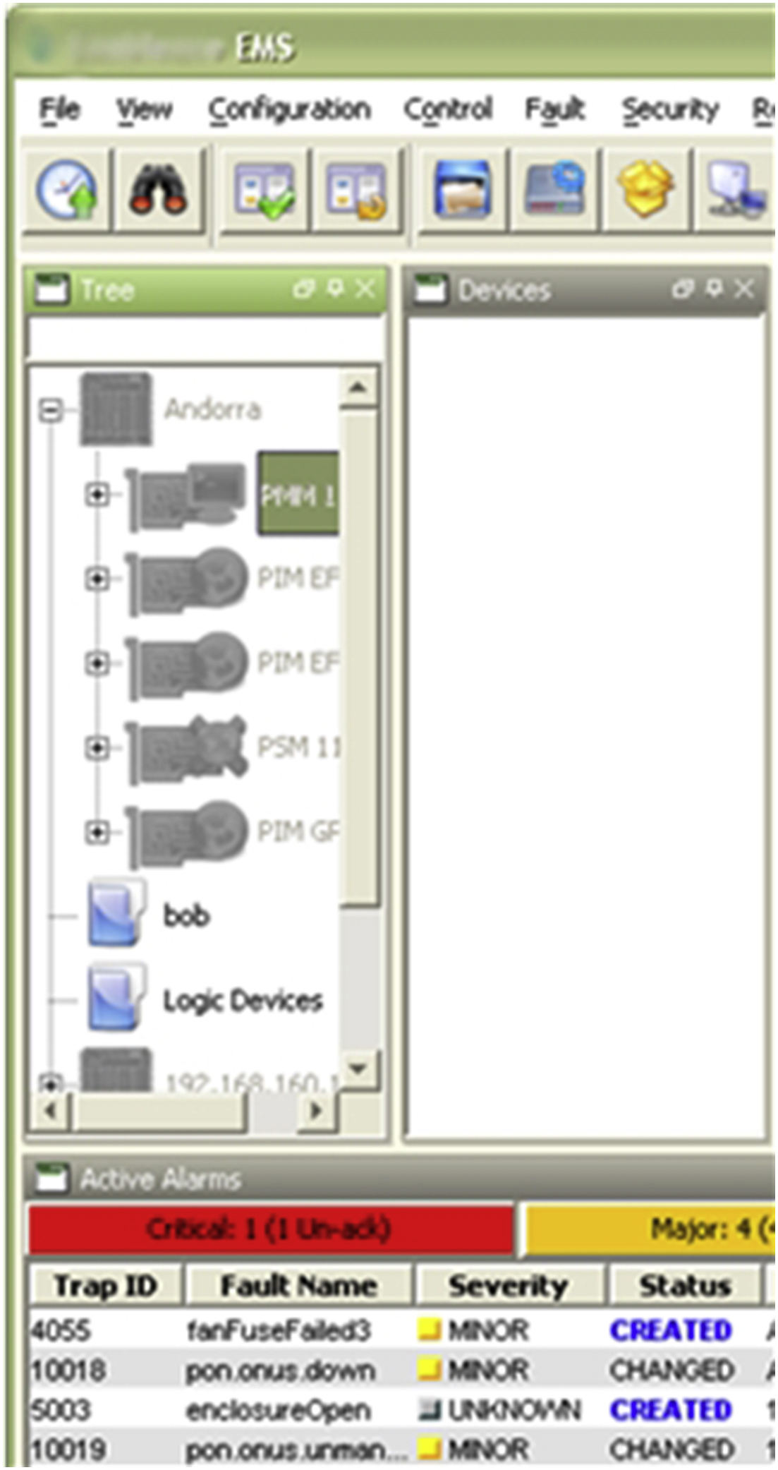
Fig. 14.5 shows an example alarm and event table in an FTTx NMS/EMS.
The key attributes of an alarm or event include the ID of the condition, the severity of the problem as defined by the operator (critical/major/minor), the source of the condition including the device name and type, the time the condition was received by the management system and finally the number of times this condition has been reported by the network element.
In today’s environment of a distributed management system it is important for a network operator to ACKnowledge each alarm they are working to resolve. This tells the operator’s staff that a colleague has already begun taking action on the condition received by the system. Enforcing this discipline is critical in order to avoid one of two undesirable outcomes: either two people start working on the same problem and work at cross-purpose, or everyone assumes someone else has it, so no one works on it.
Alarm and event notification is critical to a fault management system in order to facilitate automatic reporting to staff. Notifications are typically set up for particular alarm/event, severity level, frequency, and device types through email, SMS text message, voice message, and system alarm. These features are critical to allow for indications of various conditions and escalated problems within a managed system to be easily communicated to the staff.
Accounting Management
If there was a component of the overall system architecture which could be considered critical to the success of the entire system at all times then we would have to say that accounting management is that component. Accounting management provides far more than just visibility and processing of revenue streams within the system. Below is a listing of components which may be incorporated into the accounting management system. Depending upon the service models deployed some of these may not be necessary or you may include additional over time.
▪ Differentiated service tiers among subscribers, defined by different revenue tiers;
▪ Differentiated service tiers between residential and commercial customers;
▪ Bandwidth metering, allowing subscribers to use a defined data-rate and/or a defined amount of total data, charging additional if they choose to go over their defined limits;
▪ Differentiated on-network services hosted by the operator, such as on-network gaming.
Philosophically, accounting management should be considered as managing the expectations of the consumer on the costs he or she is incurring each billing cycle, based on the services requested. This is your primary view of revenue streams and how these revenue streams are generated based on services defined within the system. From here you can define the more popular tiers, how the tiers are being consumed, and how to predict your network growth and investments.
Configuration Management
The primary goal of configuration management is simple enough: provide the tools necessary to enable and disable services as required to ensure smooth routine operation of the system. One of the key tasks for which configuration management is responsible is taking those marketed network services and mapping them into the various managed objects within the active equipment. In other words, configuration management provides the key interface for enabling and disabling network services.
Now, this sounds simple enough; however, there are usually many managed elements that must be set up, some as simple as residential-grade Internet services or a voice line. Further, as network services change over time or new network solutions are integrated into a network, the configuration management must be capable of adapting to those changes. This may include service offerings to current network tiers (e.g., increasing data speed to all subscribers) or entirely new network architectures such as adapting a commercial services offering or the rollout of carrier Wi-Fi services.
Another artifact of the configuration management subsystem is visibility into the demand that provisioned services are having on the capability of the systems offerings. Many OSS (operational support system) platforms target the configuration management system as the responsible interface, given the knowledge of the rules justifying service creation and intimate knowledge on capacities provided by each network interface or element.
When deciding on the integration of a new OSS-based platform, a key is to make sure the configuration management solution provides interfaces which are easily adaptable to new hardware implementations. The solution should provide clean interfaces to guarantee network changes, whether this includes new service models being put into place, enabling or disabling subscriber services, or adding new network capacity.
The configuration of services within an FTTx network is rather extensive given the number of network endpoints being configured. Each of the subscriber services has a number of configuration elements required to ensure the services purchased align with the services experienced by the subscriber. The service configurations typically have configuration details as illustrated in Table 14.1.
Table 14.1
Configuration of Services Within an FTTx Network
| Service Type | Service VLAN, QoS priority, Bandwidth | Additional Configurations |
| Data (Internet) | Must specify | Client IP address management (ex. DHCP relay option 82 or IPv6 LDRA) |
| Video (RF) | N/A | Video enable/disable, optional RF return parameters |
| Video (IPTV) | Must specify | IPTV channel plan enforcement, maximum active channels, IGMP or MVR configurations |
| Voice | Must specify | Embedded VoIP client IP address management,VoIP signaling type (ex. SIP, MGCP, H.248), soft-switch or call-agent configurations, voice call features |
For other types of services such as business data (e.g., MEF E-Line and E-LAN), TDM over IP (PWE3 for T1/E1), data service for mobile-backhaul (MBH), TR-069 management, and RG (residential gateway) and WIFI, service configurations can have very different parameters.
Advanced FTTx NMS/EMS systems must allow flexible service configuration for service addition, service removal, service suspension, and service modification. Configuration tools such as the ones below are very welcome.
1. Structural service configurations
FTTx service requires many levels of configurations in order to fully function. For example, a data Internet service requires a networking profile providing details such as VLAN and IP address configuration, a security profile defining artifacts such as MAC limit and DHCP snooping (to protect network L2/L3 resources), and an SLA profile defining bandwidth and QoS parameters. The structural service configuration approach means that many profiles in each category (networking, security, and SLA) above are created in the management system, allowing for different service levels based on subscriber needs.
2. Bulk service application tool
A service package can be applied in one action to many subscribers at the same time with a live indication of progress. This tool is very useful when bulk service provisioning requirements are necessary or service modifications are implemented.
3. Service configuration scheduler
Many times service changes are performed during maintenance windows; however, the configuration of the bulk service changes take time. As configuration changes are made, a method to schedule these changes during a normal maintenance window is necessary to ensure a stable live network environment.
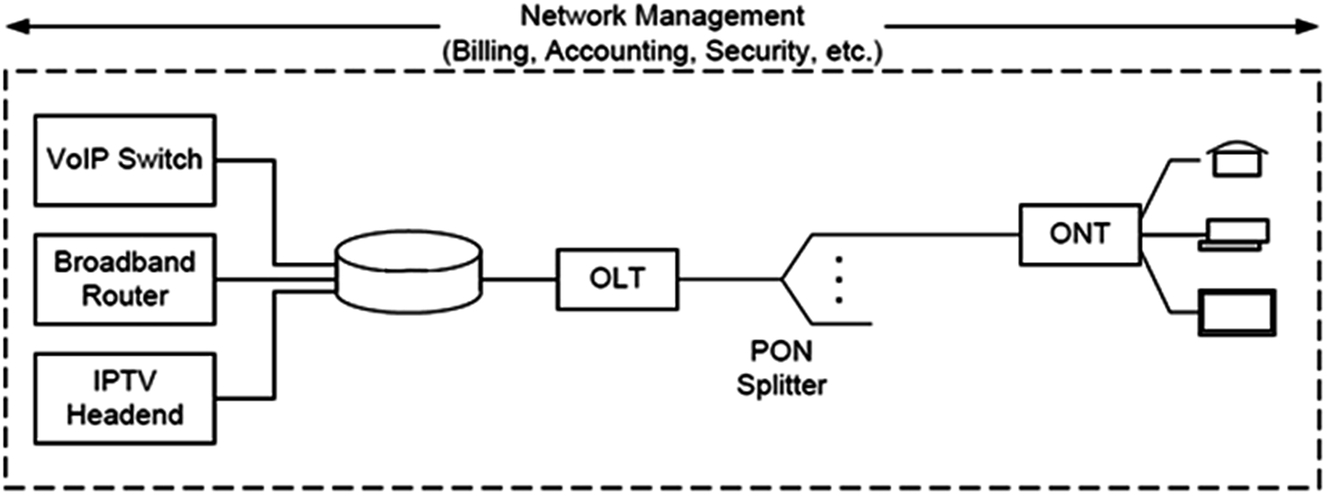
Fig. 14.6 shows an example of an FTTx NMS/EMS GUI that has IPTV and data services configured on an ONT. Notice that on the left of the GUI window are displayed all ONTs on a specific PON.
Service Provisioning and Software Management
The activation of services to a subscriber should be flawless and scalable. This allows the operator to bill customer services immediately upon installation of the ONT. A method which makes this possible is having the ability to preprovision all services within the network prior to the installation of the ONT. We describe preprovisioning below, and strongly recommend this operational model.
Service preprovision and auto-configuration speed up service turn-up. Prior to the installation of the ONT, the network operator should consider including within their management system the option for preprovisioning what can be termed as a logical ONT. A logical ONT is the exact instance of the ONT to be deployed; however, the deployment of the physical device has not commenced. All services which are to be configured to the ONT are made including all northbound systems such as voice platforms, network servers, and IPTV platforms. Upon first connection of the physical ONT, the ONT is discovered within the system and matched to the ID of the logical ONT using unique elements such as an MAC address, serial number, etc. Once the match is completed the management system automatically activates the ONT and configures the preassigned services.
Another major step in the commissioning of an ONT is to ensure the software running on the equipment is the current revision. Many times an operator will make this change to the ONT hardware prior to sending the ONT on the service truck. The does enable a much faster field installation; however, the effort to unpack, download the new software, then repacking is enormous. Another option is to automatically update the software installed on the ONT upon installation of the ONT at the subscriber’s premise. This provides an easy and automated activity allowing for significant time savings and guaranteeing the software running is consistent with the network on which the ONT is installed.
The process of upgrading software is crucial for bug fixes and for introduction of new features. A robust software management solution of the OLT and ONTs requires dual software images and backward or forward compatibility in the design. Dual image storage on the OLT and ONT assures that in the event of unforeseen software crash and network outage in the new software version just introduced, all network elements can revert to the previous known-working versions. This is typical in most carrier-grade access equipment, allowing for immediate restoration of services upon detection of a major fault detected after a software upgrade.
Configuration management for software must record active/backup/running software versions on each network element. Upgrade paths, typical pointing to an FTP or TFTP server, must allow clear graphical user interface (GUI) selection and path addition. Invalid image selection based on NE (network element) models should be enforced. And most importantly from what we learned in field deployments, is the software upgrade efficiency when using bulk upgrade. We have seen customer requirements that all ONTs under an OLT must complete upgrade within one maintenance window. This is to ensure all functionalities work properly across system software entities without impacting customer service expectations. FTTx equipment vendors have been constantly improving the speed of bulk ONT software upgrade. For example, image transfer over a management IP connection is much faster than over the standard PON OAM (EPON) and OMCI (GPON) channel because of the low bandwidth of the latter. Other techniques for improvement of upgrade speed, such as multicast transfer of software image to ONTs and ONT and software auto upgrade from the image server when a new version is detected, are being exploited.
A fundamental management task that is related to configuration management is called inventory management, which accurately tracks deployed system hardware such as OLT chassis and modules, pluggable optics, and all connected ONTs on the ODNs. The FTTx system is a last-mile access platform in which each ODN fiber can connect and provide access to more than a hundred ONTs. Each ONT can be an SFU or an MDU unit. It is easy for a chassis-based OLT to connect a few thousand ONTs and each ONT can have one to many provisioned services, voice, data, and video. An accurate inventory is necessary not just for accounting and tracking purposes, but also key in reporting level of usage of layer 2 and layer 3 service configurations such as bandwidths, VLANs, and IP addresses.
Maintaining an accurate ONT inventory in an FTTx network is key for the service provider’s day-to-day operation. The active state of an ONT [discovered (active), undiscovered (down), fault, or discovered (disabled)] under every PON is usually the first thing to check for in a reported trouble ticket.
Each ONT should also have a subscriber name or location address that is mapped to the service provider’s billing system. Inventory management information also facilitates network operations such as spare inventory, software upgrade planning, and product life cycle. Inventory management must record hardware records such as part number and revisions, serial numbers, and MAC addresses.
Performance Management
Network operators are faced with challenges when it comes to understanding those possible artifacts which may cause a decrease in performance experienced by subscribers. When a network is architected, the operator must make decisions on how the service provisioned will be “oversubscribed.” What this means is that an operator must make a capital decision on how much capacity will be available to all subscribers within the network compared to how much bandwidth is “offered” or “provisioned.” The concept of oversubscription has been around for generations, even well outside of the telecommunications world. For example, when a road is to be built a decision has to be made on how many lanes need to be provided, and in Atlanta, GA, with all the traffic there is never enough. However, it would not be prudent of the local governing authority to build a road such that there is never congestion. The governing authority just needs to continually monitor the situation such that if the situation becomes overbearing then the road must be expanded or new roads constructed. Planning is crucial because construction work takes time and taking too much time could present a series of other challenges and delays in completing the road.
The same concept must be employed by a network operator. A network must be continually monitored at all potential congestion points to determine traffic utilization. Many times operators find their highest network utilization starts around 7:00 p.m. and does not begin to taper off until much later into the evening, around midnight. People are home from work, school, and sporting activities and looking to watch the news or browse the Internet or possibly do some gaming. Performance management is the key to ensuring the network is performing at all times across the defined set of “oversubscription” levels the operator is expecting.
The performance management activities must be reviewed on a regular basis and consistently compared during each review period. Changing how data are reviewed can only mask certain data unless historical information is available to show trends. This exercise allows an operator to plan accordingly in understanding when additional capacity is required at different points in the network. Many times the addition of capacity could take a lot of time and money. This importance of tracking capacity utilization, predicting how usages may change over the next 6 months, must be part of performance management. The trick is to provide enough capacity so that subscribers don’t notice congestion, while not overprovisioning the network, which will raise cost for no offsetting revenue. Chapter 8 discusses oversubscription and the effect of quality of service (QoS) management. It suggests some good-practice numbers you might consider.
An FTTx NMS/EMS typically supports the following performance management functions:
▪ Give the status of platform resources such as CPU usage and memory usage.
▪ Gather real-time per-port or per-service transmit/receive frame and byte counts. For example, a service provider may want to verify that its business data subscriber can actually reach the contracted bandwidth throughput. Many FTTx NMS/EMS systems now support 15-min and 1-day performance management counters at the ONT subscriber ports.
▪ Gather aggregate OLT data usages—service providers will need to know the percent data usages of each PON or network interface port over a day, a week, or a month. It is also desirable to have such PM data on a per-service basis.
▪ Modern deep packet inspection (DPI) technologies make it possible to report subscriber data usage across selected URLs, protocols, and other user-defined metadata fields. These collected metadata statistics can be used to optimize network usage based on applications, lawful interception (e.g., within emails), or for marketing or research purposes.
Security Management
The final functional area should not be considered the least important. Security management is just as important as each of the other functional areas. Without a strong security policy set forth within a management system all other aspects of the system will be compromised. Over the past two decades more and more of peoples’ lives have become digitalized. As much as we would like to hope that everyone is good out in the Internet, as my mother used to say, “if there is a mud puddle in the yard, I was going to find it and make a mess of things regardless.”
An operator must take this advice from my mother to heart, understanding how critical it is that a well thought-out security policy is put into place. An operator many times may allow a subscriber to pay for services using credit cards, and that data must be carefully protected. An ambitious gamer may look to exploit all aspects of the network for possible ways to prioritize his or her data to win in a combat game. An avid but cheap sports fan may look at ways to enable the sports networks without paying for the service.
Each of these scenarios and many others are all possible opportunities for a network to be exploited. The function of a strong security management policy is to not only protect the network from those who do not have access, but also ensure those who do require access have it as required when required. A strong security management solution provides visibility as to when a network is accessed externally, as well as identifies clearly when an unauthorized or unexpected security breach is detected.
The FTTx NMS/EMS typically supports the management user security by login security control for feature and device access rights.
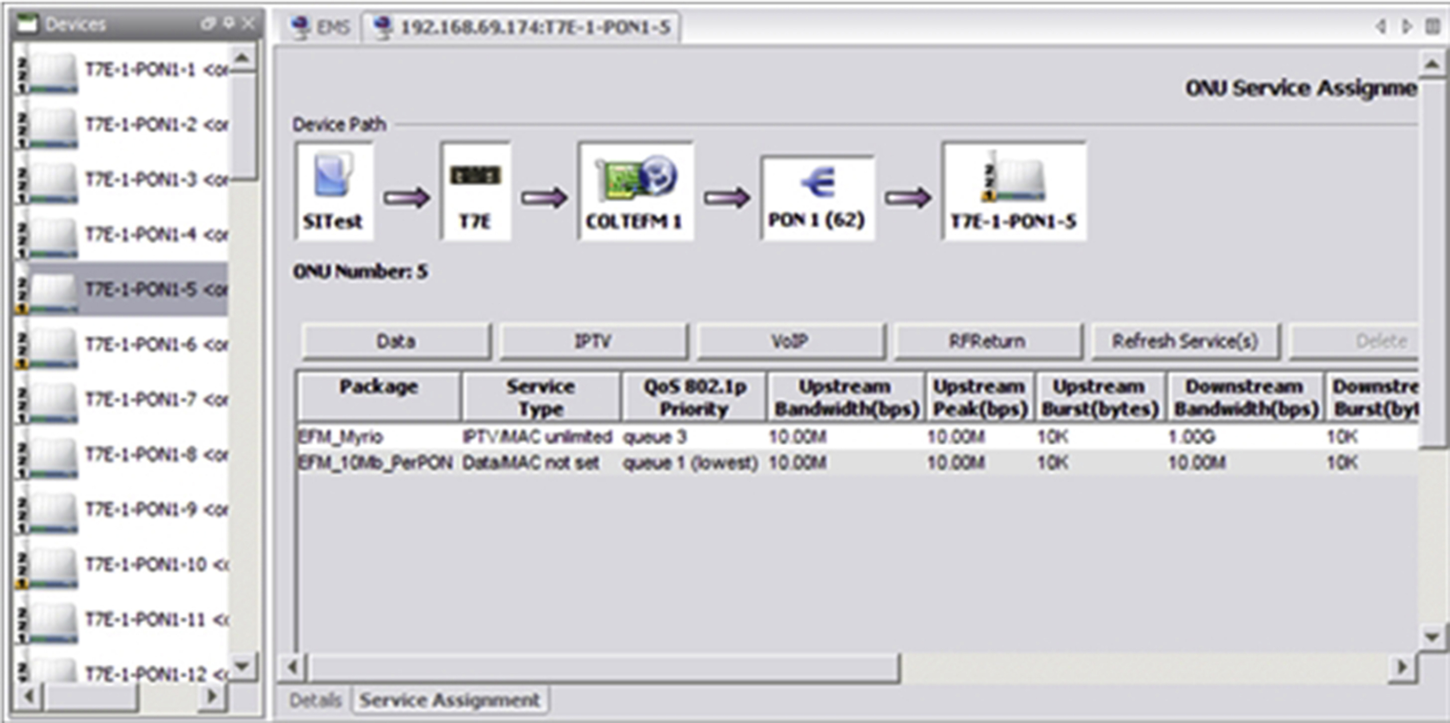
Fig. 14.7 show an FTTH EMS screen that allows the administrator to define a user group and permit or deny access right to nearly every management function.
Access rights are defined typically by a system administrator user. “View-only” access right is a read-only privilege (not service affecting) that can be, for example, assigned to tier-1 support staff who only need to verify configurations. Access rights of “Add”, “Edit”, and “Delete” can modify the service configurations and should only be assigned to higher-tier support staff for troubleshooting or service enabling/disabling.
User groups can be allowed or denied for access to any device in the system via editable device lists.
Similarly, a system admin user can assign device access rights (as defined by the system device filter in Fig. 14.7) based on ownership of the hardware on the per-PON, per-blade, or per-chassis basis. Fig. 14.8 shows that devices inaccessible to the current user are shown up as disabled (grayed out) in the GUI. This can, for example, be the case for a login user who only handles residential subscribers and does not need to see the hardware associated with the business customers.
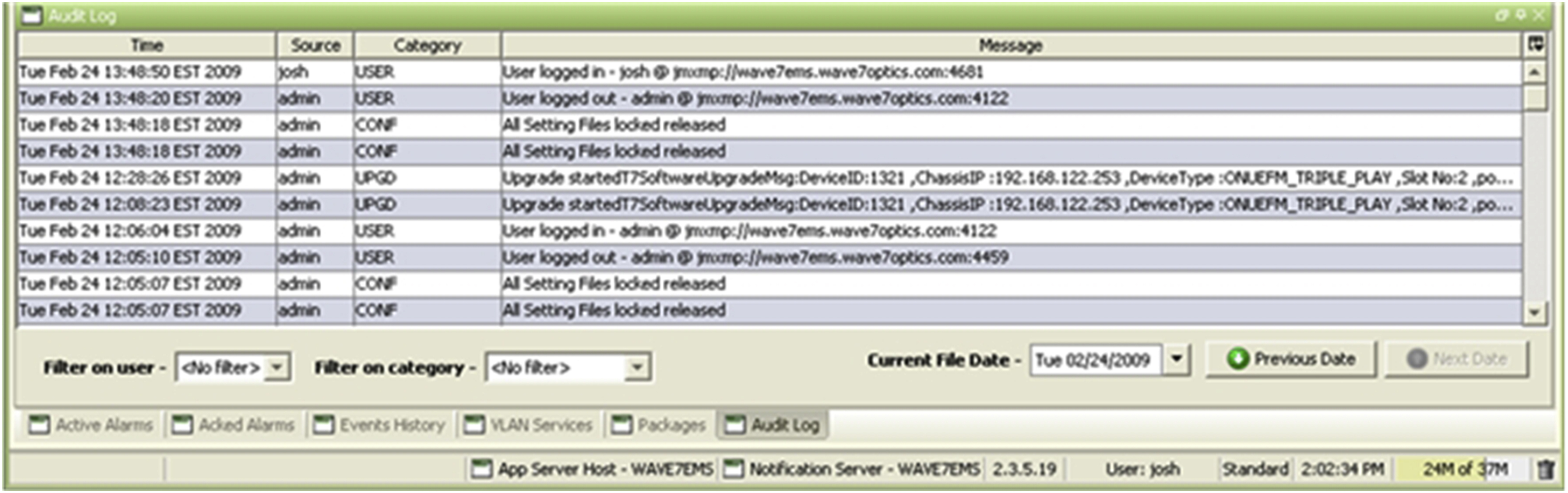
Other security features can include view current users and an audit log viewer that displays all previous user actions in the system. Fig. 14.9 shows an example of audit log that has the attributes of action time, user name, category, and detailed description of action.
Troubleshooting and Maintenance
As FTTx platforms are deployed for mission-critical services, trouble-shooting and maintenance features are now being requested. Many technologies have matured for such purposes, and equipment vendors are beginning to include them in their product offering. The following are a few solutions which assist in troubleshooting an FTTx deployment.
Ethernet OAM CFM and Y.1731 Management
Connectivity fault management (CFM) as defined in IEEE802.1ag is an end-to-end per-service-instance Ethernet layer operation, administration, and management (OAM) protocol. It includes proactive connectivity monitoring, fault verification, and fault isolation for large Ethernet metropolitan-area networks (MANs) and wide-area networks (WANs). ITU-T Y.1731 defines similar functionalities and adds performance management. In comparison, IEEE802.3ah (the original EPON standard, now subsumed into 802.3) EFM only defines link-layer fault management.
Fig. 14.10 shows where MIP (in circles) and Up MEP (up arrow) and Down MEP (down arrow) are defined for three MD (management domain) levels for CFM application in GPON network as defined in TR-156 Sec. 6.1 for 1:1 VLANs.
The FTTx NMS/EMS must support:
▪ CCM (continuity check message) statistics—An MEP generates CCM messages to announce its local port and interface status. When CCM is enabled, an MA (maintenance association) tracks CCM messages from all MEPs, and is performed at a defined interval.
▪ LBM (loopback message) and LBR (loopback reply message)—An MEP generates an LBM message when the CFM loopback test is performed. An MEP/MIP responds with an LBR message when it receives an LBM message destined to its own MAC address.
▪ LTM (linktrace message) and LTR (linktrace reply message)—An MEP generates an LTM message when link trace is performed. An MEP responds with an LTR message when it receives an LTM message.
When Y.1731 is supported, the management system also needs to report management performance counters, including frame delay (FD), frame delay variation (FDV), and frame loss ratio (FLR).
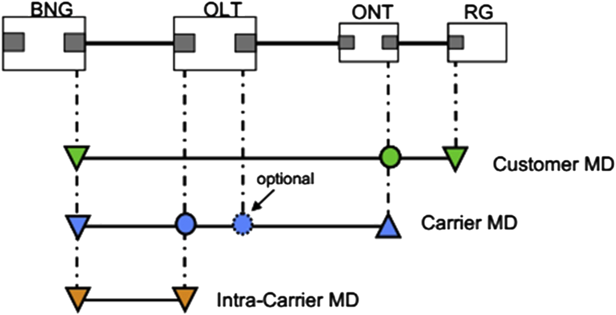
For example, when CCM monitoring is enabled at the BNG, it can monitor at a defined interval the CCM messages from the MEP on the customer MD. This assures the L2 connectivity across the FTTH segment.
As another example, on the carrier MD an MEP can generate a CFM LBM message when the CFM loopback test is performed. The MEP/MIP on this MD responds with an LBR message when it receives an LBM destined to its own MAC address. As can be seen this is similar to the L3 “ping,” and why the CFM loopback function is called “MAC Ping.”
OTDR Monitoring (for Physical Layer Debugging)
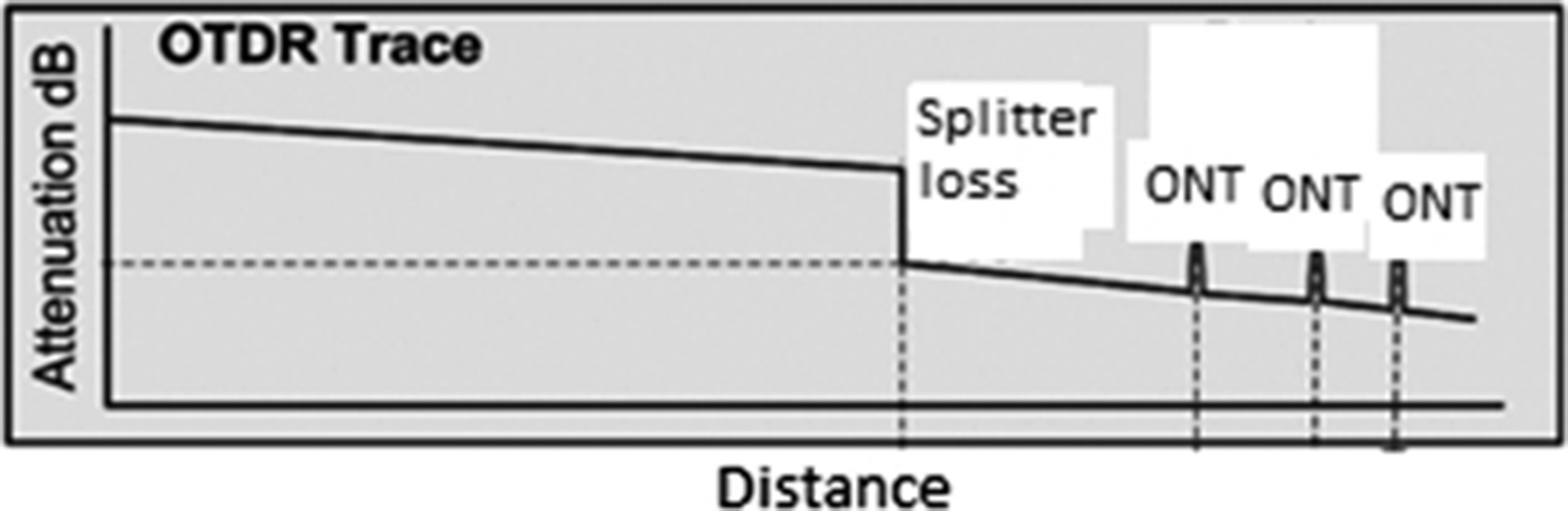
OTDR (optical time domain reflectometry) provides a very convenient way to troubleshoot problems in the fiber plant itself. It gives you a picture of how the light propagates through the fiber, and can show splices, connectors, splitters, and breaks or other fiber faults. You will find that an OTDR is your best physical-layer troubleshooting tool. A typical PON OTDR trace will look like the one in Fig. 14.11. A simple single-stage splitter is in the ODN.
The industry has converged on the OTDR wavelength as 1650 nm, considering current and future versions of EPON and GPON, plus point-to-point overlay and RF video and return. This wavelength will pass through modern fiber optic cable, but is not used for transmission to subscribers.
Note that if two or more ONTs happen to be at the same distance from the OLT, within the distance resolution (typically 2–3 m) their reflection peaks will collide with each other.
In a PON network with a maximum of about 30 dB ODN loss (1 × 64 plus 20 or 40 km fiber), it is a challenge for the OTDR to see the ONT reflection peaks. This is why the Broadband Forum TR-287 (PON Optical-Layer Management, Issue 1, June 2014)vi still leaves a few specifications for the “drop fiber reflection event” as for-future-study (FFS). A workaround is to use a reflection mirror at the input of the ONTs. This reflects much more light at the OTDR wavelength back to the OLT, improving the signal-to-noise ratio of the measurement. Technically it works, but it creates an operational headache for already deployed sites. However, there are vendors who can detect the ONT reflection without using the reflection mirror by using advanced single processing techniques.
A PON NMS/EMS with OTDR capability must map each logical ONT subscriber to the physical ONT reflection peaks. Although the OLT provides accurate ranging distances, EPON RTT (round trip time) or GPON EqD (equalization delay), equipment vendors still need to calibrate the offsets due to different ONT PON SoC (system-on-a-chip) integrated circuits being used—some may add more delay than others to the ranging signal, introducing errors that must be calibrated out. Proper calibration must be included in the embedded software to use a unique offset time constant for RTT or EqD based on the SoC type or the ONT model being discovered.
PON OTDR tests can be on-demand or routine (scheduled) tasks, depending on the needs. When a subscriber reports service outage, the OTDR capability can clearly sort it out if the issue is physical-layer related. The FTTx NMS/EMS must be able to launch an OTDR test for any PON, report fault location, stored history test results, and trigger alarm and notification.
Forced Protection Switch
ITU G.984.1 [Gigabit-capable passive optical networks (GPON): General Characteristics. 03/2008] defines four types of protection. These can be used to protect high-value customers from physical layer faults and some electronic faults, at the expense of extra equipment and fiber routing. The most common two types that FTTH vendors have implemented are type B and type C. Protection is only defined for GPON and may or may not have been implemented by a given manufacturer, and certain EPON manufacturers may have implemented their own protection, which may or may not work as shown below.
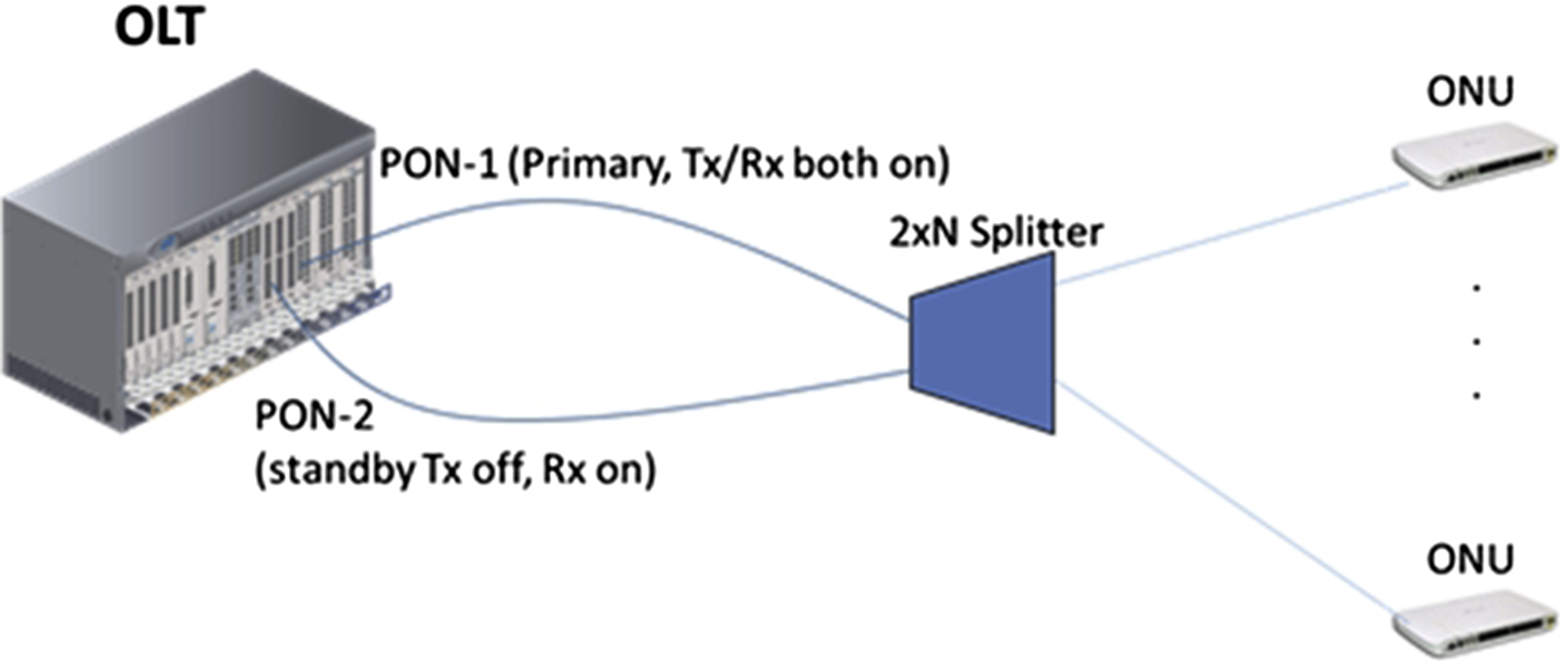
In both types of PON protection, automatic protection switching (APS) is typically enabled by default. For type B normally one OLT PON port is active (Tx/Rx both on) and the other is in standby (Tx off, Rx on) (Fig. 14.12). APS is controlled by the OLT. For type C protection, both PONs are always active and software on the ONU controls which PON is active (Fig. 14.13). When failure is detected on the active PON, the embedded software will automatically switch to the standby PON. Traffic protection with less than 50 ms interruption can be achieved. For type B protection a switch-over requires reranging of the ONTs to the new OLT port, which could take many seconds. There are methods of sharing the ranging distance values between the primary OLT and the secondary OLT such that the convergence of ranging takes place faster, but 50 ms is still difficult to achieve. One method is using the GPON POPUP message for faster ONU state transition. Obviously type C is more expensive and therefore typically deployed for business customers and at the emerging MBH (mobile backhaul) ONT sites. Note that real installation will prefer the two PON ports are on different OLT line cards, which can protect line-card hardware failure.

When RF video overlay on FTTx is deployed, additional protection-switching mechanism needs to be installed to protect the video light signal (typically 1550 nm) when this is ODN fiber cut.
While switching is normally automatic, there will be need to use the FTTx NMS/EMS to issue a “force switching” to the standby facility, for example, for planned ODN network upgrade or transceiver swapping in OLT or ONUs.
Summary
The management of telecommunications systems has been in place since the birth of nonverbal communication. Over the years the industry has defined a series of functional areas which all should be considered regardless of the size of the network or the complexity of the services put into place. Although these functional areas were defined some time ago not much has changed in defining the importance of these areas, even as networks have become highly integrated and more complex.
..................Content has been hidden....................
You can't read the all page of ebook, please click here login for view all page.