
CHAPTER 8
![]()
Fritzing Arduino (and Other Boards)
Fritzing is a very accessible tool. It was designed from the outset as a tool for hobbyists rather than professional electrical engineers. As such, it is often used as a means of documenting and designing projects that use an Arduino, Raspberry Pi, BeagleBone Black, or other low-cost controller boards that are popular with amateurs and inventors.
What’s more, it is also easy to use Fritzing to design Arduino shields. They are plug-in boards that piggyback the popular Arduino microcontroller development boards.
Breadboarding with Microcontroller Boards
Fritzing includes parts in the parts bin for a wide range of Arduino boards as well as for the Photon and the Raspberry Pi and BeagleBone single-board computers. If you are planning a project based on one of these boards, then drawing out a neat breadboard diagram is a great way of documenting the design.
Arduino
In a later section you will see how easy it is to use Fritzing to create an Arduino Shield, an add-on board that fits over the top of Arduino into its header sockets. But in this section, I concentrate on creating breadboard designs with various types of Arduino.
It used to be that if you wanted to use a microcontroller in a project, you would need to master some tricky programming and probably a Windows-only development environment to program the microcontroller. What’s more, you would have to spend time with datasheets understanding just how the device you wanted to use worked, setting fuses and using specialized programming hardware. This made it barely worthwhile for hobbyist users who just wanted something quick and easy to control some electronics.
The Arduino has revolutionized the use of microcontrollers. This small board (in its most popular form, the Arduino Uno) is little more than an ATmega328 microcontroller chip and some extra supporting components, including a power supply, USB interface, and crystal. It has an easy-to-use C library and development platform that will run on Windows, Mac, and Linux. You can then program the board through its USB interface. The USB interface can also be used for communication between the Arduino and a regular computer.
If you want to learn more about the Arduino and how to program it, you might like to read the book Programming Arduino: Getting Started with Sketches, also by Simon Monk.
Arduino Uno R3
The Arduino Uno is the most common of the Arduino boards; of these, the latest incarnation is the R3 (revision 3). Fritzing includes an Arduino R3 board. You will probably want to use a breadboard with the Arduino, so when both are added, you can start joining things with virtual jumper wires.
Figure 8-1 shows the Arduino design that you first saw as an example in Chapter 3.

FIGURE 8-1 Breadboard layout with an Arduino Uno.
The Arduino has a useful regulated power supply that can provide both 5V up to 500mA and 3.3V up to 40mA to components on the breadboard. It is therefore quite common to connect power lines from Arduino GND and 5V to the supply rails on the breadboard.
It is a good idea to color-code the wires and then use the same colored wires when you actually connect things between the breadboard and Arduino.
Having the breadboard and Arduino side by side can cause wires to become detached when you move things about. You can buy plastic holders that have one section for the Arduino and a second section for the breadboard. This keeps the whole project together.
Arduino Pro-Mini and Nano
Several of the Arduino models are actually designed to be breadboard-ready and will fit onto solderless breadboard. The Arduino Nano is essentially an Arduino Leonardo (the same pin layout as the Arduino Uno, but a different microcontroller) that has been shrunk to fit onto breadboard.
The Arduino Pro-Mini is an altogether simpler device without a USB interface. Instead, a separate USB adapter is used when programming the Pro-Mini. This avoids the waste of having a USB interface built into the board that is required only during development.
Figure 8-2 shows an Arduino Nano and Pro-Mini with a USB programming adapter attached; Figure 8-3 shows an Arduino Nano on breadboard connected to an LED.

FIGURE 8-2 An Arduino Nano and Pro-Mini with USB adapter attached.

FIGURE 8-3 An Arduino Nano on breadboard with an LED.
Raspberry Pi and BeagleBone Black
Fritzing also has parts for the Raspberry Pi and BeagleBone Black, which you can use in just the same way as an Arduino Uno. At the time of writing, the new Raspberry Pi models B+ and A+ are not yet available as parts, but the older A and B models are available.
Protoshield Design
Once you have prototyped an Arduino-based project on breadboard, it can be useful to build something a little more solid before you take the step of designing PCBs. Arduino Protoshields are a good way of soldering a design without needing a custom PCB.
An Arduino protoshield is a shield that plugs on top of an Arduino and contains a large prototyping area. You can push through-hole components through the holes on the top of the board and then solder them together on the underside. Figure 8-4 shows an example of a protoshield project mounted on an Arduino Uno.
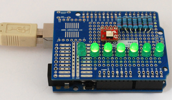
FIGURE 8-4 An Arduino protoshield project.
Fritzing includes a Protoshield part. From the schematic view, the protoshield looks just like an Arduino (Figure 8-5a), and on the Breadboard view, you can treat the board the same as breadboard (Figure 8-5b).

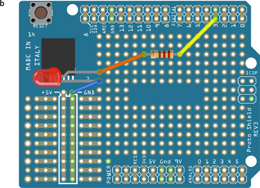
FIGURE 8-5 Using an Arduino Protoshield in Fritzing.
On the Breadboard view, each pad is not normally connected to any other pad and just offers a secure way of anchoring the part. You will notice that some of the pads are connected; for example, the two columns labeled +5V and GND on the left of the board are connected to the Arduino 5V and GND connections using PCB tracks on the protoshield. This serves a similar purpose to the columns of holes down the sides of solderless breadboard.
Off-Board Arduino
Although the Arduino is a fantastic tool for putting together a prototype, it does not usually make sense for an Arduino board (even a Nano or Mini) to be included in a final product. When it comes to the final product, you will want to take the parts from the Arduino that you need for your invention and add in the extra parts that were connected to the Arduino.
Removing the ATmega IC
A good approach to a project such as this might be to first prototype your system on breadboard with an Arduino Uno. Then once it is all working and you have the software working, you can carefully remove the microcontroller IC from its socket on the Arduino Uno and place the programmed chip onto the breadboard, as shown in Figure 8-6.

FIGURE 8-6 Basic off-board Arduino.
When you remove the ATmega chip, carefully ease the chip up out of the IC socket with a screwdriver, lifting each end in turn until it comes out of the socket easily. Be careful, as it is quite easy to badly bend the pins that may then break off.
Note that there are actually two versions of the Arduino Uno, the Uno and the Uno SMD. The Uno SMD costs less, but you cannot remove the microcontroller, so it is not suitable for taking your designs of the Arduino onto breadboard.
If you needed to reprogram the microcontroller, you would need to take it off the breadboard and pop it back into the Arduino Uno for reprogramming. But make sure that you put it back the right way around. Pin 1 of the chip (indicated by a dot next to the pin) goes to the end of the Uno farthest from the USB socket.
Figure 8-7 shows the schematic diagram, breadboard layout, and PCB layout for the off-board Arduino. You can find the Fritzing file for this with the downloads for the book in the file ch_08_Arduino_baseline.fzz. All the downloads for the book are available from the author’s website at www.simonmonk.org.


FIGURE 8-7 Off-board Arduino schematic, breadboard layout, and PCB layout.
There is no voltage regulator, but the ATmega microcontroller IC will operate from 3 to 5.5V, so you can power a circuit such as this with two or three AA batteries. The other components included are the quartz crystal, capacitors, a couple of resistors, and an LED.
Arduino Bootloader
The ATmega microcontrollers used in Arduino boards are preprogrammed with something called a bootloader. The bootloader is what allows Arduinos to be programmed over USB or using a USB to serial adapter.
If you buy an ATmega328 IC from a manufacturer, it is unlikely to come preprogrammed with the bootloader, and special programming hardware is needed to install the bootloader. However, if you search the Internet, you will find a number of sources for ATmega328s that have the bootloader installed for a little extra cost. In fact, Shrimping.it, described next, can supply the ATmega328 with bootloader.
Shrimping.it
Taking the microcontroller off an Arduino reveals just how little of the Arduino you really need to make a microcontroller-based project.
Building a Shrimp on breadboard is an approach promoted by @ShrimpingIt (described online at www.shrimping.it). They demonstrate how easy it is to construct an Arduino-compatible circuit on solderless breadboard. The documentation provided guides people through the construction of various Arduino-compatible projects using prototyping materials. This is cheaper than using an official Arduino board, and it also offers the educational value of constructing the whole circuit from scratch. It is an open procurement project, meaning build designs are freely shared and instructions are provided to buy bulk components directly from wholesalers. For smaller volumes or for reduced hassle, low-cost kits can be purchased from @ShrimpingIt directly. This is a great way of getting everything you need for your first experiments with off-board Arduino prototyping.
With the Shrimping.it approach, the microcontroller is programmed through a USB adapter similar to the one used for the Arduino Pro-Mini; and the ATmega328 microcontrollers supplied by Shrimping.it are preprogrammed with the Arduino bootloader, so you can program them as if they were Arduino Unos from the Arduino IDE.
Making an Arduino Shield
Sometimes an invention is designed for other inventors and makers. For example, you may decide to design an Arduino shield to be manufactured and sold to other makers and inventors. In this section you will learn how to create an LED lighting controller as an Arduino shield.
Creating an Arduino shield design in Fritzing leads very naturally from the breadboard prototype that would precede it. As an example, you could easily design a shield that uses three MOSFET transistors to control 12V LED lighting. These are not your regular LEDs, but rather 2 to 5W, 12V DC LED lamps intended for domestic lighting. Using the shield on an Arduino, you would be able to turn these three lights on and off and control their brightness. You will find an Arduino test sketch for this with the downloads for the book at www.simonmonk.org along with the Fritzing file for this project, which is called ch_08_lighting_shield.fzz.
Breadboard Layout
In this project, begin with the breadboard layout. It makes sense to start with just one of the three lighting channels and then duplicate the other two when the first channel is working. Figure 8-8 shows the breadboard layout for just one channel.

FIGURE 8-8 Breadboard design for one channel.
The Arduino will be supplied with 12V DC through its DC jack. The 12V will then be available at the Vin pin, which can supply the power to the LED lamps, each of which will be switched by a MOSFET. The design is actually very similar to the motor control design in Chapter 4.
The components are all from the CORE parts bin, except the screw terminal just below the MOSFET. That terminal can be found by searching for Screw Terminal and selecting the option with 0.2in pin spacing. Eventually, the lamp will be attached to the screw terminal on the PCB, but during testing on breadboard, a combination of male-to-male jumper wires and alligator leads will work just fine (see Figure 8-9).

FIGURE 8-9 Prototyping the lighting controller on breadboard.
Add the Other Channels
Build the first channel on breadboard and test it out, before you add the other two channels to the design by selecting the MOSFET, the screw terminal, the resistor, and the leads to the resistor and screw terminal and using the Duplicate option on the right-click menu.
Reposition the groups of components, add in the wires to Arduino pins D10 and D9, and you should end up with a breadboard layout that looks like Figure 8-10.

FIGURE 8-10 Final breadboard layout for the shield.
Test all three channels (just in case), and then you are ready to start designing the PCB.
Layout of the PCB
When you first switch over to the PCB tab, you will see something like Figure 8-11. Note that I have changed the background to white.

FIGURE 8-11 The initial PCB view for the Arduino shield project.
The components are all over the place, and although there is the outline of an Arduino board, this represents the Arduino itself, not the PCB for the shield. The PCB for the shield is currently rectangular, so select the PCB and then, using the Inspector, change the board shape to “Arduino Shield.”
Now line up the Arduino itself and the shield, so that the pins are in the right place. You will also need to separate out the components that you duplicated earlier that will be stacked on top of one another.
Finally, drag all the parts onto the PCB, and do the usual rotating and label tidying, to produce component positions as shown in Figure 8-12. Start by positioning the screw terminals, as these need to be easily accessible from the side of the board.
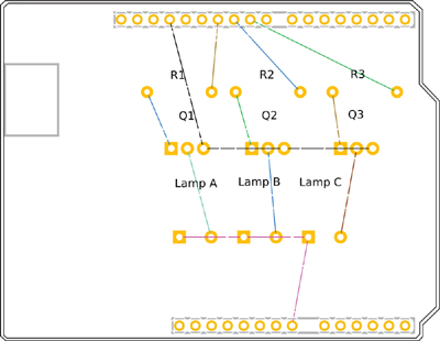
FIGURE 8-12 Parts in position and ready for routing.
When positioning the through-hole parts on the shield, you need to think about the underside of the shield and what’s on Arduino below. The screw terminals, in particular, have fairly long through-hole leads that could touch something metallic on the Arduino below. Making a paper prototype for a project like this is always worthwhile.
The nets on this design fall into one of two categories. There are power nets, which will be carrying significant but not huge currents (6W at 12V is 0.5A), and then there are control nets that turn the transistors on and off, through which very small currents will flow. The current will be at most a few tens of milliamperes. That is, after all, the whole point of using a MOSFET as a switch.
It makes sense to route the control signals in standard 24 mil traces but to use something thicker for the power connections. Do the routing on the underside, to keep the top surface of the design clean. The end result should look like Figure 8-13.

FIGURE 8-13 The final routed Arduino lighting shield.
There is actually quite a lot of room on the left of the PCB, so a nice touch would be to put a table showing which Arduino pin is used for which lighting channel.
Summary
In this chapter we have explored the use of Fritzing to support the use of Arduino and other prototyping boards.
In Chapter 9 you will learn how to modify and add parts to the Fritzing parts bin.