
CHAPTER 6 Degradation Faults and Software
Learning objectives of this chapter are to understand:
• The role of redundancy and replication in computer system architecture.
• The role of software in managing the redundancy in computer systems.
• The impact on software architecture of redundancy in computer systems.
• What software has to do to support redundant system architectures.
• The effects on software of operating on system architectures such as triple modular redundancy.
6.1 Impact on Software
Computer systems have to deal with degradation faults, and so the obvious thing to do is to use the four basic approaches, i.e., avoidance, elimination, tolerance, and forecasting, in a systematic way. In practice, that is what is done, but three of the four, avoidance, elimination, and forecasting of degradation faults, are quite specialized and beyond the scope of this book. Fault avoidance and elimination for computer hardware, for example, requires extensive, specialized knowledge of hardware technology, and fault forecasting requires detailed knowledge of the underlying probabilistic models and the associated methods of analysis.
In our discussion of degradation faults, therefore, we limit our attention to fault tolerance and, within that topic, to the aspects of the problem that are important to us as software engineers or computer engineers. Our goal is not to develop or analyze fault-tolerant structures that might be used for coping with degradation faults, although we will describe them. Our goal is to understand how such techniques impact software, both its development and its operation. This impact is quite extensive. The result of having to deal with degradation faults affects software in two ways:
Target Platform Architecture. The target platform upon which the software executes can be a lot more complicated than might be expected. Equipment is present that would not be needed if our goal was merely to execute the software. As a minimum, the software has to execute properly with this target.
Software Functionality. The software is usually called upon to help manage the target system. Tolerating degradation faults might require assistance from the software in all four phases. Software might be used (a) to detect errors by comparing data from different hardware elements, (b) to assess damage by examining data from the different components or running diagnostic tests designed to determine which components have failed, (c) to establish a consistent state by reconfiguring both the hardware components and the software itself, and (d) to provide continued service by stopping, starting, or reconfiguring either hardware or software components. Tolerating degradation faults might lead to different or reduced service, and that change might require extensive processing by the software.
As we proceed, we will assume that the degradation faults of interest are those which have been properly anticipated and whose existence has been analyzed using the techniques described in Chapter 5. We will also assume that the failure semantics associated with each degradation fault are properly defined and comprehensive.
6.2 Redundancy
6.2.1 Redundancy and Replication
Tolerating degradation faults relies upon redundancy. Redundancy does not mean simple replication, although replication is commonly used. Replication means having multiple instances of an entity that might fail available when fewer than that number are required to provide service. Having multiple instances of an entity leads to the obvious possibility that, when some of the entities fail, other replicates can continue to provide service. For example, if one entity is required but we have two, then service can be continued if one fails, at least in principle.
Clearly, replication is expensive. If we only need one of something to provide service, then having two will cost roughly twice as much. With this in mind, various less expensive techniques have been developed in which complete replication is not needed. Some additional, redundant equipment is required but less than would be needed with an exact copy.
Parity
A simple example of redundancy that is not replication is memory parity. Parity provides a form of degradation fault tolerance that is limited to error detection. A single parity bit is added to a set of data bits and is set to make the parity either even or odd. One parity bit might be used for many data bits, a byte, or a 32-bit word, for example. If a fault leads to one of the data bits or the parity bit being inverted, then the parity will be incorrect and specialized circuitry can detect the situation1.
With parity, all that we have is error detection, because the location of the defective bit (or bits) is unknown. However, in many cases error detection is adequate. In terms of our notion of fault tolerance, error detection is achieved by observing the parity discrepancy, damage assessment is to assume that the entire set of data and parity bits is defective, and both state restoration and continued service are null. Thus, in terms of repairing the data bits, nothing useful can be done if parity checking is all that is available, and so continued service is limited to stopping.
Adding parity to a memory of any size is a useful capability. The system can detect an important class of errors, and measures outside of the basic memory mechanism can provide some form of alternate service at a higher level of abstraction. If these errors are not detected when they occur, the erroneous state could become much worse, as computing would continue with either incorrect data or incorrect instructions.
Note that parity deals with a particular type of fault, typically the loss of a single bit from a prescribed set. Thus, this has to be the anticipated fault for which parity is being added. Part of the process of anticipating the fault has to include the determination of the number of data bits for each parity bit and the failure semantics of individual data bits.
Error-Correcting Codes
Another example of a system that uses redundancy which is not replication is an error-correcting code for memory. In this case, the fault tolerance allows the effects of the fault to be masked. The data is not replicated, but additional information is stored along with the data. The additional information requires more bits than simple parity but fewer bits than the data.
If a bounded number of bits is lost either from the data or the additional information or both, then it can be recovered algorithmically. The most common instance of a code of this type is designed to deal with a loss of a single bit from a set of four. This requires three bits in addition to the four bits of data along with circuitry to make use of the additional bits. In this simple form, the additional bits are referred to as the syndrome. An error is signaled by the syndrome being non-zero. Damage assessment is to assume that only a single bit is erroneous, in which case, the nonzero syndrome is actually the location of the erroneous bit. State restoration is provided by inverting the erroneous bit, and continued service by resuming the operating software.
Mirrored Disks
An example of a system that uses redundancy which is replication to mask faults is a mirrored disk, as shown in Figure 6.1. In such a system, two disks are used in place of one, and each holds a complete copy of the data. If either disk fails as a result of an anticipated fault, the other disk can continue to support both read and write operations within the file system.
During the time that one of the disks is being repaired or replaced after a disk failure, the system is vulnerable to a second disk failure and so the probability of complete failure is non-zero. The system designers have to make sure that the probability of a second disk failure during that time is sufficiently small. Provided the failed disk can be replaced as a maintenance activity, the system can become fully replicated again as soon as all the data has been written to the replacement disk, a process called “resilvering”.
RAID Systems
A generalization of the idea of mirrored disks is the set of architectures that is known as Redundant Array of Inexpensive Disk (RAID) systems [104]. There are several different disk architectures within the set, the simplest of which is exactly disk mirroring. Adding more complexity allows substantial benefits to be gained both in terms of performance and dependability. For example, the architecture known as RAID 2 uses an approach that is similar to error-correcting codes in memory. Instead of writing data sequentially on a single disk, a set of n bits is written across n disks, one bit per disk. The additional bits needed by the error-correcting code are also written across a set of disks, one bit at a time. With this arrangement, a disk read failure can be masked, and a complete disk replaced if necessary without stopping the system.

FIGURE 6.1 A mirrored disk system in which two identical copies of the data are maintained.
6.2.2 Large vs. Small Component Redundancy
No matter what techniques are used to tolerate degradation faults, a decision has to be made about the size of the components to which fault tolerance will be applied. In the cases of parity and error correction discussed above, for example, deciding how many bits will be protected by a single parity bit or a single instance of error-correcting data is necessary. The reason for this choice is partly cost and partly the efficacy of damage assessment.
The issue of cost is fairly clear. Redundancy requires something additional in a system, even if that something is not complete replication, and so to keep costs down we would like to use as little redundancy as possible. In the case of parity, for example, the least additional memory requirement would occur if we used a single parity bit for an entire real memory (perhaps several gigabytes). The cost and organization of the parity generation and parity checking circuitry is another expense.
The problem of dealing with large components using minimal redundancy is that minimal redundancy limits the opportunity for damage assessment and therefore the continued service that can be provided. No matter what the size of a component is, the component to which redundancy is applied is the limit of damage assessment. During operation, complete failure of the component has to be assumed, even though this is rarely the case. Thus, of necessity, all of the working parts of a component are taken out of service along with those parts that have failed. If the designers’ choice was to apply redundancy to large components, then large amounts of working hardware will be lost following any failure. If the choice had been to use redundancy on small components, reconfiguring what remains to assemble a working system is far more likely to be possible, albeit perhaps with reduced functionality.
The contrast is shown in Figure 6.2 In the upper diagram, a system consisting of an A component and a B component is replicated in its entirety. In the lower diagram, the individual components are replicated and connected in a flexible way. In the upper figure, a failure of component A makes the entire replicate unavailable, including a perfectly good B component. If the remaining B unit fails, the system will become non-operational.
In the lower figure, all that is lost if an A component fails is that A component. Subsequent failure of a B component (but not an A component) can be dealt with because the remaining A component can be connected to the remaining B component.
As an extreme example of the issues surrounding component size, consider the parity example again. If a single parity bit is used for an entire memory, then the entire memory is lost when a parity error is detected. However, if a single parity bit is used on each 32-bit word, then only one word is lost when a parity error is detected. Avoiding using part of memory is relatively easy for software if that part is known to be defective.
6.2.3 Static vs. Dynamic Redundancy
Although redundancy is needed for all aspects of fault tolerance, the same redundant elements are not necessarily used for all four phases. Certain elements might be used for error detection and entirely different elements used to provide continued service. The most important instance of this occurs with the notions of static and dynamic redundancy.

FIGURE 6.2 System in which redundancy is applied to (a) large components and (b) small components.
In practice, electronic components fail because of thermal stress, vibration, humidity, and physical damage. Thermal stress arises because of high absolute temperatures and temperatures that vary over time. Damage from thermal stress leads to an important idea, which is to extend the life of components intended to facilitate continued service by keeping them powered down. In other words, those components that are not needed for the provision of service are not operating. Keeping an electronic component powered down tends to increase the time to failure of the device.
Keeping a device powered down is not a panacea for longevity. The device is still subject to some temperature variation, vibration, and humidity, and possibly to physical damage. The most significant problem is the restoration of power when the device is needed. Failure rates at power on are relatively high. A second issue is that the power on operation is not transparent. Powering on a component frequently requires cessation of service while the new component is initialized, and other devices and the software are reconfigured.
Operating all of the devices in a system all the time is referred to as static redundancy. Keeping redundant devices powered down until needed is an approach called dynamic redundancy. In such a system, a set of j devices is needed to provide service and error detection, and these components are operated all the time. A set of k additional components is included in the system, and these devices are kept powered down until needed. The number of spares, k, can be set to provide an extended period of service if necessary. With the high reliability of modern devices, the value of k is sometimes just one or two.
The contrast between static and dynamic redundancy is illustrated in Figure 6.3. In Figure 6.3(a), static redundancy, the system begins with N operating units and the number of operating units decreases as units fail. In Figure 6.3(b), dynamic redundancy, the system begins with N–S operating units and S spares. The number of operating units remains the same at N–S as units fail, because spares are entered into the operating set.
6.3 Redundant Architectures
Many different redundant architectures have been developed, far too many to be discussed here. In practice, the design and development of the architecture for a specific system is a complex activity, and the purpose of discussing redundant architectures is twofold: (1) to review the basic architectural types and (2) to examine the implications on software of each architecture.
Employing redundancy in a system is an expensive and complicated undertaking. Any system that employs a redundant architecture incurs costs over and above those needed for the basic operation of the system. The additional costs incurred during development include:

FIGURE 6.3 (a) Static redundancy versus (b) dynamic redundancy.
• Acquisition of hardware and software that constitute the redundant elements.
• Development of custom, system-specific hardware and software needed to effect the desired redundancy in the system.
• System verification and validation.
The additional costs incurred during operation include:
• Consumption of additional power.

FIGURE 6.4 Dual-redundant architecture.
• Dissipation of additional heat.
• Supporting and perhaps moving additional weight.
• Provision of additional space.
Are these costs worthwhile? The value depends, of course, upon the probability of failure and the consequences of failure. Increased power demand might not be reasonable on a spacecraft if the spacecraft uses computer components that have demonstrated a small probability of failure. In an aircraft system, the weight of redundant components might be intolerable. On a submarine, power and weight are unlikely to be problematic, but the physical space required might not be available.
In this section, we review five basic redundant architectures. Each could be used as part of a strategy for tolerating degradation faults at the complete processor or memory level, at the functional unit or memory unit level, or at the component level. Significant enhancements would have to be made to the simple forms discussed here in order to deal with all of the anticipated faults at the processor or memory level. Those enhancements would be the subject of a great deal of analysis both to determine whether they should be used and what the effect would be.
In Section 6.4 we look briefly at the probabilities of failure of the various redundant architectures.
6.3.1 Dual Redundancy
A simple redundant architecture that is in common use is the dual-redundant architecture shown in Figure 6.4. In this architecture, two identical components are operated in parallel, and the results are compared. The operation of the components is synchronized by the use of a common clock, and the results of the two components are expected to be the same.
Phases of Fault Tolerance
Error detection is achieved by comparing the outputs of the two components. If they differ, then an error has occurred. Following error detection, determining what has failed — component 1, component 2, the comparator, the power source, or some other system component — is impossible. Thus, the only damage assessment that is possible is to consider the entire system to have failed. State restoration therefore is reduced to disabling the system entirely, and continued service is reduced to a total absence of service.
Effect on Dependability
The effect on dependability of a dual-redundant system is quite complex. Surprisingly, the MTTF is actually reduced. We examine this in section Section 6.4. So why would such an architecture even be considered? The reason is that a dual-redundant system provides error detection. Error detection is not possible with a single component unless the component is supplemented in some way, because there is nothing in the system to determine that the system’s state is erroneous. The negative impact of an erroneous state arising and not being detected is obviously unbounded. This architecture is one of the simplest ways to create a supplement that can detect the effects of a substantial set of degradation faults. As expected, this architecture cannot detect design faults in the components.
Impact on Software
The impact on software of the dual-redundant architecture seems as if it would be minimal. The detection of errors is purely by hardware, and once an error is detected, the whole system is shut down. Thus, following error detection, the software has no opportunity to react. What might software have to do?
The impact on software is not as simple as it looks, because the software has to take precautions before a component fails. For both systems software and applications software, software developers have to be concerned about two things:
Deterministic environment. The software’s operating environment must be deterministic. Although the two components are operating off a single clock, making the operating environment deterministic is still difficult. If the two software systems communicate separately with a peripheral device, they almost certainly would not see identical timing. The difference in timing could cause the two software systems to behave non-deterministically. Thus, provision has to be made for inputs to be distributed carefully from any source. Even if the same scheduling algorithm is used, the processor timing will differ, thereby offering the possibility of divergence between threads if one gets ahead of another. This probably means no paging since that affects speed and requires a peripheral disk. Care has to be taken with cache management to be sure cache content is identical. Finally, various internal processor clocks could differ, so there is a need to synchronize the machines periodically.
Deterministic software. In a related issue, the software must not use any programming techniques that might lead to non-determinism. The most obvious example of such a technique is concurrency, the use of multiple threads or processes. Even if they are identical down to the bit level, making two concurrent software systems deterministic is essentially impossible. One option, therefore, is to avoid concurrency completely. This option is not especially desirable, because many applications are built with concurrent algorithms. If threads are going to be used, then they must operate with a non-preemptive scheduler so that there is no dependence on a system clock for switching between threads. Non-preemptive scheduling means that threads stop executing when they block and not because some timer expires. Although the high-level architecture of such a system includes a “clock”, that clock is not very well defined. Even if the clock meant the actual hardware oscillator, you could not count on precisely the same timing between the two units because of different individual delays.
Fortunately, there is a relatively simple way to deal with all the issues of determinacy identified above. The idea is to synchronize either (a) only when output is to be generated (as seen by the comparator) or (b) on some artificial fixed schedule. In most real-time systems, output is generated at the end of each real-time frame. If identical software is used in both processors, the effects discussed above can mostly be ignored, provided both systems operate with the same real-time clock and frame rate. For example, the Space Shuttle used four machines in the on-board Primary Flight Computer and they synchronized every 40 milliseconds.
Non-real-time systems can synchronize on a fixed time boundary, i.e., define a set of specific synchronization points in the code that requires the two units to synchronize.
Typical Application Domains
A dual-redundant architecture only provides error detection, and so the architecture cannot be used alone for systems that require high reliability or availability. Dual redundancy is a good approach to the design of monitoring systems, as discussed in Section 2.6.5 on page 40.
As we saw in Section 2.6.5, the utility of error detection followed by system shutdown should not be underestimated. Frequently, not knowing that something is wrong is far more important than something being wrong. In aircraft, for example, many systems are provided to help the pilot in various ways. In many cases, if these systems are unavailable, the situation is acceptable provided that the pilot is aware of the lack of availability. Thus, error detection coupled with a simple warning system is often sufficient.
Details of the Dual-Redundant Architecture
Before leaving the dual-redundant architecture, looking at the architecture in more detail is instructive. By applying fault tree analysis, we can quickly develop quite a long list of events that need to be addressed, but which are not addressed by the basic architecture since the concern is with the major, duplicated component. Specifically, we find the following events are not dealt with:
Comparator failure. If the comparator fails, there is no comprehensive error detection mechanism, and so the system might continue operating for an arbitrary time.
Clock failure. The clock is an important component, and clock failure might allow the duplicate units to diverge or cease operating completely.
Input distribution mechanism failure. If the input is not distributed correctly, the possibility exists for the duplicate units to generate different outputs even though they have not failed.
Distribution to comparator failure. The signals from the duplicate components might not be presented correctly to the comparator.
Output distribution failure. The output of the comparator, presumed correct, might not be supplied to the subsequent user of the output.
Power failure. Clearly, if all or part of the system loses power, the effect would be catastrophic.
These details and many more in a typical practical installation have to be addressed by system designers using a dual-redundant architecture.
6.3.2 Switched Dual Redundancy
The switched, dual-redundant architecture is shown in Figure 6.5. Despite the similarity, the switched dual-redundant architecture is quite different from the dual-redundant architecture. The philosophy is to supplement either one of the duplicate units or both with an error-detection mechanism, and to replace the comparator with a switch.

FIGURE 6.5 Switched dual-redundant architecture.
Error Detection Mechanisms
High-end computers frequently include extensive error detection as part of their basic design. An excellent example is the IBM Power6 [93]. There are many hardware techniques that can provide error detection without replication, including:
Parity. Parity can be applied to data buses in processors and to processor registers just as it can be applied to real memory. Hardware defects frequently manifest themselves as dropped bits that can be detected with parity.
Error Detection and Correction. Just as parity can be checked within non-memory components, more sophisticated error detection and error correction mechanisms can be used within non-memory components. Multiple-bit errors do occur and need to be detected, and additional value is gained by correcting single-bit errors.
Watchdog Timers. Timers that monitor temporal aspects of a system are often referred to as watchdog timers. They are set by either hardware or software to contain a value that is determined by the characteristics of the system. Separately, the watchdog timer is either reset if disabled by a subsequent event that is expected to happen. If the expected event does not happen, then the watchdog timer will expire and raise a signal of some sort. If a hardware failure within a processor causes the sequencing of events to be disrupted, then a watchdog timer can be used to detect the disruption. Clearly, watchdog timers are useful for software as well as hardware error detection. In particular, they can be used to detect and escape from infinite loops.
Memory Protection. Many hardware failures cause addresses to become damaged, and that damage could cause data to be read or written from a protected location. In that case, memory protection mechanisms can detect the event. In addition, marking the role of memory as read, write, or execute can prevent incorrect use of memory.
Integrity Checks. Various types of check can be performed on data to assess its integrity. Cyclic redundancy checks, for example, apply a function to blocks of data in series, and the result can be stored. If the computation is repeated, the result should be the same, and, if it is not, then an error has occurred.
Arithmetic Checks. Numerous properties of binary arithmetic have been studied that partition results into two equivalence classes, feasible answers and infeasible answers. Thus, many defects in computer arithmetic that result from defects in processing units can be detected without circuit duplication.
As well as error-detection mechanisms, many machines also include simple approaches to state restoration and continued service such as instruction retry. A processor that includes instruction retry makes provision for:
• Reversing the effects of a failed instruction in the local processor registers.
• Reissuing the instruction, perhaps multiple times.
Instruction retry works in circumstances where a transient degradation fault has occurred.
Even without techniques such as instruction retry, built-in error detection can be quite extensive. Thus, a switched dual-redundant system can be built quite effectively with off-the-shelf equipment, and the result is a system in which both units include extensive error detection. Provided the transition to an erroneous state is signalled suitably, the result is very effective.
Care has to be taken with the failure semantics of the processors. Although there are several techniques that can be used to detect errors in the primary component, modeling their coverage is difficult. This raises doubt about the quality of the error detection that can be achieved. Is it possible to actually miss an error? The answer is certainly “yes”, and so error detection is stochastic. Even for well-defined but abstract failures, such as failure to compute an arithmetic result correctly, error detection is difficult unless full-scale duplication is used.
A second concern is that error detection might not occur until after the damage to the state has become serious. Thus, the software might have continued to operate after the state has become damaged but before the error is detected. Such an occurrence could be catastrophic.
Finally, if the processor fails and the failure is not detected, the possibility exists of unbounded damage. A solution to this is provided by fail-stop machines, which are discussed in Section 6.5.
Types of Spare
In a switched, dual-redundant system, one of the units, referred to as the primary unit, is used to provide service, and the other is referred to as the backup unit. Under normal operation, only the primary unit is used. The health of this unit is monitored by the error-detection mechanism, and the primary unit’s outputs are made available by the switch. If the error-detection mechanism determines that the primary unit has failed, the backup unit becomes operational, and the switch supplies the output of the backup unit to the system. Since the service during normal operation is provided by the primary unit, the question arises of how the backup unit should be operated when it is not in use. There are three options:
Cold spare. The backup unit could be completely idle and not conduct any application-related computations at all. In fact, the backup unit could even remain powered off. In this case, the backup is referred to as a cold spare. In order to take over operation, the backup unit has to create all of the necessary state and then the switch has to start forwarding outputs from the backup to the rest of the system.
Warm spare. The backup unit could prepare to take over if needed but otherwise not conduct any of the operations that the primary unit does. Of particular importance for the backup unit is to maintain its disk status in a form that would allow it to take over service. In this case, the backup is referred to as a warm spare. In order to take over operation, the backup unit has to change its operation to compute everything that is required, enhance its state to match that of the primary unit just before it failed, and the switch has to start forwarding outputs from the backup to the rest of the system.
Since the backup has the capacity to provide the same service as the primary unit, the backup is largely idle when the primary unit is operating. The temptation to use the unit for some sort of additional service is rarely resisted, and running so-called non-critical functions on the backup unit when it is configured as a warm spare is common.
Hot spare. The backup unit could operate exactly as the primary unit does, including undertaking all computations but discarding them. In this case, the backup is referred to as a hot spare. In order to take over operation, all that is needed is for the switch to start forwarding outputs from the backup to the rest of the system.
Phases of Fault Tolerance
Since error detection does not involve the second of the duplicate units, damage assessment can be assumed to be restricted to the primary unit. State restoration is then relatively simple, because all that is needed is to start the backup unit operating and switch the source of outputs. Finally, continued service can be quite substantial since there is no net loss of operational equipment, although there is no longer a spare. Keep in mind that, following failure of the primary unit, there is no spare and that the system is vulnerable to complete failure. If the spare uses the same checking technology as the primary, then the error-detection mechanism will provide protection against continued operation with a failed unit.
Effect on Dependability
The effect on dependability of a switched, dual-redundant architecture is complex but quite substantial. An increase in the system’s MTTF seems likely, because two separate units operate in series until failure of both occurs. This is only partially correct because of the action of the switch. By going to extraordinary lengths, the effects of the failure of the primary component can be masked, so that the system provides continuous service. Without these extraordinary lengths, the output is not continuous because of the need to initialize the backup unit and to make the switchover. Not masking the effect of the fault is the common case, because there are far more satisfactory ways of masking the effects of a fault.
Finally, note that all of the fault types not associated with the primary unit that were discussed in Section 6.3.1 have to be addressed with this architecture also.
Impact on Software
Software plays a major role in the switched, dual-redundant architecture. First, the backup unit has to have custom software if the unit is to be a warm spare. The state that the backup unit keeps is determined by the applications being supported and the mechanism to be used for switching units. For a backup that is operated as a cold spare, custom software is needed to initialize the spare when the spare has to take over. Finally, for a backup operated as a hot spare, custom software is needed just to support basic operation. The difficulty in this case is that the operation of a system is often intimately connected to the state of the operating environment.
Consider a web server, for example. The Hypertext Transfer Protocol (HTTP) employs the Transmission Control Protocol (TCP) and TCP requires various interactions between the client and the server. These interactions have to be “faked” for the hot spare because it actually has no interaction with the client. Faking will involve some synchronization between the primary unit and the backup unit so that the backup unit maintains exactly the same state as the primary unit.
Several system-level design issues are raised by this architecture that affect the software significantly, including:
• How the system’s two halves are connected to the service network.
• Where the two halves are located.
• How the two halves communicate.
• Whether the various parts listed are handled as separate problems.
• The level of repeated activity that will be tolerated by the users.
As an example of the difficult issues that software has to deal with, consider the case of a cold spare. During normal operation, nothing need be done by the software because the spare machine, being cold, is doing other things. The problem is these “other things”. If the primary fails, the secondary has to stop what it is doing. Thus, the secondary has to make sure that the shutdown times of the active applications that it is running are bounded. This is not necessarily trivial because every application has to be assessed for shutdown time.
Next, there has to be a complete system restart on the spare machine. Unless the operation of the primary was restricted to transactions (which is a common case), there is a good chance that the file system is in some sort of state of disarray. Thus, a check of the file system upon restart might be needed. In practice, many systems of this type are, in fact, designed for transaction processing, and so a great deal can be gained in terms of system recovery. In particular, if the system includes a database, then the database will be consistent and only contain completed and committed transactions.
In practice, for a system using a cold spare, complete replication is rarely used. Different components are treated differently. For example, application servers might be replicated, but the system might use a single, dependable database. If there is a single database, then the software only need be concerned about the servers. If there is, in fact, a replicated database, then the copy needs to be a true copy. Such a system could be built by just recording a log of database updates that is replayed when the backup system’s private database has to go live.
Unless the system is restricted to transactions, there will have been incomplete operations underway, and that means various inconsistencies with application data structures. Software has to be available to make the data structures consistent. Finally, the applications designed to run on the primary have to be started on the secondary, and the secondary has to be linked into the system environment so as to be able to operate. This linking might mean redirection of communication links and switching of specialized peripherals such as special displays or printers.
Typical Application Domains
Given the limitations in error detection and the time required to switch between the primary and the backup unit with a switched, dual-redundant architecture, using the architecture to support a system that requires high reliability is unlikely. The architecture could be used for systems requiring high availability, although the difficulty of quantifying the performance of error detection makes quantifying the resulting availability difficult.
Faults cannot be masked effectively, so there will be a disturbance in service. The degree of disruption can range from an apparent lack of response as seen by a user to the user having to log on again, repeat certain activities, etc. What effect is seen will depend on various system characteristics, such as the start time for applications, whether the file system is damaged, the number of applications, the number of users, etc.
The switched dual-redundant architecture is most commonly used in systems where the expense of doing more is not considered cost effective or where the expense is prohibitive. Examples of the former are systems that provide business data processing. Such systems need to maintain levels of availability that are only moderate but which typically cannot be achieved without fault tolerance. Frequently, business data processing systems are complex because the associated business requires substantial amounts of data storage, transmission, and processing. The major service units, however, are often constructed as switched dual-redundant units.
An example of a system for which the cost of duplication is prohibitive but which still needs higher availability than would occur without fault tolerance is a wide-area network. Replicating the complete network is prohibitively expensive because the network includes compute and data-storage nodes, networking equipment, and so on. Consider, for example, the idea of building a complete duplicate of the Internet. This would, of course, be completely unrealistic. Instead, critical components such as servers are sometimes built as switched dual-redundant systems with the necessary repair times determining which type of backup — cold, warm, or hot — is used. In the case of a packet-switched, wide-area network there is no need to replicate the routing network explicitly because of the inherent redundancy in the packet network.
6.3.3 N-Modular Redundancy
The N-modular redundant architecture is shown in Figure 6.6. The concept is to operate a set of “N” identical units in parallel, and to vote on the collection of outputs. Since the units are identical, the expectation is that the outputs will be the same unless one or more of the parallel units is defective. An important special case is triple modular redundancy (TMR) in which N = 3.
N-modular redundancy is a generalization of dual redundancy (Section 6.3.1), i.e., dual redundancy is essentially N-modular redundancy with N = 2. With N greater than 2, a comparator is no longer sufficient because several output values have to be compared.
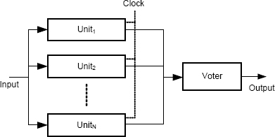
FIGURE 6.6 N-modular redundant architecture.
Phases of Fault Tolerance
Error detection in N-modular redundancy is based on the assumption that any difference in the values received by the voter indicate a failure of one or more of the N units. Provided there is a majority value, the units providing the majority value can be assumed not to have failed, and so damage assessment is to assume that units not in the majority have failed. State restoration is trivial because the states of the majority units can be assumed to be correct, and so all that is needed in state restoration is to arrange to ignore the units in the minority. Continued service is achieved by taking the outputs of the majority. Importantly, none of these steps needs to disrupt processing, and so the effects of a fault can be totally masked.
Effect on Dependability
The use of replication in the N-modular redundancy architecture provides a high level of assurance that errors resulting from degradation faults in the replicated units will be detected. This performance is in sharp contrast to the error detection that is possible with architectures such as switched dual redundancy. Since faults are masked with this architecture, the result is an increase in reliability, possibly a large increase. In fact, since N is not fixed, systems can be built in which reliability can be made quite close to one for protracted time periods.
As we have seen before, the complete analysis of this architecture as it might be instantiated in a real system is a complex and detailed process. Developing a high level of assurance that all single points of failure have been identified and properly dealt with requires comprehensive fault tree analysis, determination and assurance of the failure semantics of the components, and a comprehensive program of testing using fault injection to confirm that all anticipated faults will be treated properly.
The special case of the TMR architecture has an interesting extension that helps the overall dependability. This extension is called “TMR/Simplex” and it was originally proposed by Bal1 and Hardie [15]. The idea is that when a single processor fails in a TMR system, the remaining two processors constitute a self-checking pair. That is useful, but recall that the MTBF of a self-checking pair is less than that of a single processor. The TMR/Simplex idea is to avoid that reduction by using just one processor after the first failure. In other words, if one processor fails and two are left, turn off one of the remaining two good processors. The downside is that the system loses its error-detection capability. This is not an issue because a disagreement between processors in a self-checking pair leads to system shutdown and so a loss of service. If the system operates with just a single processor, the result is that there is a loss of service once the processor fails. But that would happen with the self-checking pair anyway and, on average, far earlier than with the single processor.
Impact on Software
The impact on software is essentially identical to the impact from the dual-redundant architecture discussed in Section 6.3.1. The key software issue is determinacy. The software running on the individual computer must operate so that the results supplied to the voter are identical or can be shown unambiguously to be equivalent.
Typical Application Domains
N-modular redundancy is the most expensive but also the most capable architecture that we have discussed. As such, NMR is used in application domains where reliability is the central attribute of dependability that is needed. Many aircraft systems that provide service that has to be continuous use some form of N-modular redundancy. Flight-control systems, for example, are the digital link between the pilot and the aircraft’s control surfaces. As such, a flight-control system must be operating properly for the aircraft to be controllable. Clearly, some form of N-modular redundancy is the best choice for such applications.
6.3.4 Hybrid Redundancy
Hybrid redundancy is the architectural realization of dynamic redundancy. Essential hybrid redundancy is NMR with a set of spare units.
Basic Architecture
The basic architecture is shown in Figure 6.7. A total of N units are operated in parallel, and S of the units are not powered. Each of the S units is available to replace an operating unit that fails. If N–S is at least three, then failures of the operating units can be masked provided a second failure does not occur during the repair. Repairs can continue until all S of the spare units has been brought into operation.

FIGURE 6.7 Hybrid redundancy with S spare units that are normally not powered.
Phases of Fault Tolerance
The phases of fault tolerance are similar to those in N-modular redundancy. The voter is responsible for detecting failure, and damage assessment assumes total failure of the replicated unit. State restoration and continued service are different because of the availability of a replacement unit. State restoration, therefore, consists of powering up one of the spare units and enabling its connections to the input and to the voter. Finally, continued service is identical to the service before failure, because the total number of units is unchanged.
Effect on Dependability
The effect on dependability of hybrid redundancy is the most substantial of all the architectures we have examined. Since degradation faults are masked, the architecture can be used for applications requiring reliability. The existence of multiple spare units that are expected to have long lifetimes means that the total service time can be very long.
Impact on Software
A lot of software is needed to enable the dependability potential of hybrid redundancy. The state of each spare has to be established when the spare is brought into operation. The issues are the same as those that arise in the switched dual-redundant architecture that operates with a cold spare (Section 6.3.2). In addition, the software running on the operating units has to be organized so that voting can operate correctly as with N-modular redundancy (Section 6.3.3). Finally, software is needed to monitor and model the complete architecture. Since the architecture provides long-term reliability, care has to be taken to maximize lifetime as the spares are used up. Rather than relying upon service remaining identical during the system’s operational life, provision can be made to reduce service as the number of available spares declines.
Typical Application Domains
Hybrid redundancy is most often used in systems that require long periods of service without maintenance, such as spacecraft, remote monitoring systems, and systems located in hazardous environments. Care has to be taken to make sure that the non-transparency of the switchover that occurs when a unit is replaced is not a limitation. In spacecraft, for example, some systems, such as those that control engine burns, have to be reliable, although only for short periods of time. For these systems, either hybrid redundancy cannot be used or the switchover mechanism has to be disabled during certain operations. This restriction is not severe, however, because engine control is needed rarely and only for brief periods. By contrast, the command-uplink system has to be highly available and it has to operate for years at a time. Loss of the command-uplink system for brief periods when failed devices are being replaced is unlikely to be a problem.
6.4 Quantifying the Benefits of Redundancy
As we saw in Section 6.3, employing redundancy in a system is an expensive and complicated undertaking. Recall that the costs incurred during development include the additional hardware and software, the design effort, and additional effort in verification. The costs incurred during operation include additional space, power, and cooling. The benefits claimed are an improvement in dependability, but the improvement needs to be quantified if appropriate system trade-offs are to be made.
6.4.1 Statistical Independence
The benefit of hardware redundancy lies in the property that hardware components, when operating in a suitable environment, tend to exhibit failures that are statistically independent. The property of statistical independence is crucial, because this property allows a large improvement in system failure rate to be achieved by employing redundancy. Replication is the commonest form of redundancy, and we discuss a simple but illustrative probabilistic model of replication in this section.
The definition of statistical independence is that, if two events, A and B, have probabilities of occurrence pA and pB per unit time, then the probability that both events will occur in the same unit of time is (pA × pB). If these two probabilities are reasonably small, then their product is much smaller than either. The probabilities are also virtually constant through the useful lifetime of most devices, i.e., the period following infant mortality and prior to end of life on the bathtub curve (Section 3.5.1).
This remarkable outcome of statistical independence is the primary reason why we are able to build systems that can tolerate degradation faults and thereby to continue to provide service for protracted time periods. Statistical independence of failures is also the motivation behind the various architectures described in this chapter.
If two events are not statistically independent, the probability that both events will occur in the same time unit could be anything. If the two events are disjoint, i.e., they cannot occur together, then the probability that both events will occur in the same time unit is zero.
Statistical independence can be assumed for hardware degradation faults in different units under circumstances where there is no common cause of failure. Although this point seems obvious, its impact is considerable. In order to be confident that a probabilistic model based on statistical independence for a specific system can be trusted, the developers of the model have to be assured that there are no significant common causes of failure. For computers, the types of thing that can derail models include:
Common sources of power. If multiple devices are fed from the same power source, they will all fail at the same time if the power source fails.
Common sources of environmental degradation. Unexpected extreme temperatures, humidity levels, radiation levels, and vibration levels can lead to higher rates of failure in all the devices in the environment.
Common sources of physical trauma. If multiple devices are located close to each other and some sort of physical trauma occurs, then all of the devices will be affected.
Such common causes of failure apply to all of a computer system’s components, not just the processing or storage elements. In particular, communications equipment that feeds data to replicated processors or storage units needs itself to be replicated. And for such communications equipment, geographic separation of the physical units (cables, modems, etc.) must be considered, especially cables. Cables are usually not in protected machine rooms, and frequently are miles in length.
6.4.2 Dual-Redundant Architecture
Recall from Section 6.3.1 that a dual-redundant architecture has no mechanism for damage assessment and so is forced to stop when one unit fails. This characteristic leads to an unusual and somewhat counter-intuitive result.
Suppose that the two units in a dual-redundant architecture have probability of failure per unit time p. For a single unit, the expected time to failure is 1/p time units. Ignoring the failure rate of the comparator, the probability of failure per unit time of the architecture, i.e., failure of either unit or both per unit time, is 2p – p2, and the expected time to failure is 1/(2p – p2). This is about half the expected time to failure for a single unit.
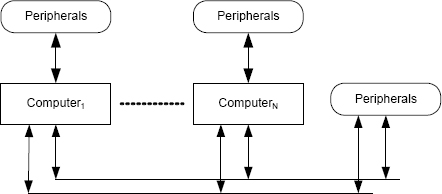
FIGURE 6.8 The basic architecture of a distributed system. Multiple computers communicate via one or more communications buses. The computers can be heterogeneous or homogeneous, and different computers within the system can have different peripherals attached. Peripherals for common use can be connected directly to the communications bus.
Things seem to have gotten a lot worse, but that is not the case. The mean time to failure has been cut in half, but that is the price we pay for error detection. The great benefit of this architecture is that, for certain types of error, the architecture provides error detection. A single unit running in isolation cannot detect errors, and so operating just a single unit leaves us vulnerable to continuing operation with an undetected error.
6.5 Distributed Systems and Fail-Stop Computers
6.5.1 Distributed Systems
Distributed systems have become familiar because of their application in the networks that we use. A distributed system includes some number of computers that communicate via one or more communications mechanisms. Each computer could have peripherals connected, and other peripherals could be connected directly to the communications mechanisms. The basic architecture of a distributed system is shown in Figure 6.8.
The advent of distributed systems has brought many advantages, including:
Flexibility. Distributed systems provide flexibility by allowing differing numbers of computers to be used in different applications. Systems that require more computing resources can use more computers and vice versa.
Placement. Computers can be placed conveniently in the physical environment, thereby allowing more effective use of space.
Heterogeneity. Computers and peripherals can be heterogeneous, thereby allowing different types of computers to be used for different parts of the application.
Degraded Service. Computation remains feasible after some subset of the computers in the system has failed. Although some performance will have been lost, continuing to provide critical services can be considered.
Applications that require high dependability can benefit from all of these various advantages, but the last one — computation remains feasible after some subset of the computers in the system has failed — is clearly a major advantage. Obviously, the ability to provide service after a failure has to be designed into the system, especially the software, and this type of design is a challenging task. Nevertheless, from a dependability point of view, a distributed system offers a great deal of potential.
6.5.2 Failure Semantics of Computers
An important question that developers of distributed systems have to address is: “What happens to a computer when it fails?” This question is not obvious, and most system developers do not think of it. Answering this question is crucial, however, because a failed computer might do a lot of damage after it has stopped providing dependable service. For example, once failed, a computer might:
• Stop executing instructions and remain silent.
• Continue to fetch instructions but from the wrong address.
• Continue to execute instructions but compute incorrect values.
• Any combination of things like this in any order and with any duration.
Put more formally, the real question is: “What are the failure semantics of the computers in the system?” As we discussed in Section 3.8, the failure semantics of a component are the semantics presented at the component’s interface when the component fails.
Anything other than immediately ceasing to execute instructions could cause harm to the state. Even if the computer ceased executing instructions, the way in which the computer ceased might mean that some data items were damaged or that correct data became inaccessible. Unless the failure semantics of failed computers in a distributed system are both well defined and assured, the benefits of having a distributed system are reduced significantly because the system’s state post failure will be unknown. What is needed is the following:
• A precise definition of the failure semantics of a failed computer.
• A means of implementing those failure semantics.
The requisite definition and the associated implementation mechanism were developed in the theory of fail-stop computers. Although the technology of fail-stop computers was motivated by the needs of distributed systems, the technology obviously should be considered (and probably applied) to all the other architectures discussed in this chapter. Defining and assuring failure semantics are important.
6.5.3 Exploiting Distributed Systems
Before discussing fail-stop computers, we consider an intriguing idea for their application. The fact that losing some of the computers in a distributed system does not remove all computational capability suggests a technique based on the following four steps as a way to achieve dependability:
• Build computers so that they fail with precise failure semantics.
• Construct the system as a distributed system.
• Design the applications so that they can be reconfigured if necessary either to stop in a predictable way or be modified to reduce their computational demand in some way.
• Reconfigure the system to provide modified service after one or more computers fail.
These four steps are actually reasonably practical. The first step is provided by the theory of fail-stop computers, and the second is routine. The third and fourth steps require that we architect the system carefully.
This technique does not seem especially different or important until one realizes the following:
Building computers that are ultra reliable is difficult.
Building computers that fail with precise failure semantics is easier.
What these observations mean is that, if the goals of an application could be stated so as to make this technique applicable, we would have an easier task in developing the system. Another way to think of these observations is that focusing on perfection in dependable computing systems might not be the best approach. Instead, building computers that fail in a predictable way and combining such computers in a distributed system might be a better approach.
6.5.4 The Fail-Stop Concept
The concept of fail-stop processors was introduced by Schlichting and Schneider in 1983 [127]. Subsequently, Schneider presented an approach to their implementation [126]. The term that Schlichting and Schneider used was fail-stop processors, although their concept includes storage and so we use the term fail-stop computers here.
Informally, a fail-stop computer is a computer that becomes totally benign, i.e., does nothing, after the completion of the last instruction executed before the failure. Formally, Schlichting and Schneider defined a set of properties for fail-stop computers that are more than this simple notion of functional cessation. These properties make the fail-stop computer concept an ideal building block for constructing distributed systems.
From the perspective of the interface presented to the rest of the system, a fail-stop computer has three basic properties:
Halt-on-failure property. The halt-on-failure property means quite literally that the computer ceases all state changes after the last correct instruction was executed. Importantly, this property means that the computer does not “babble”, i.e., constantly generate meaningless output values, nor does the computer generate erroneous but meaningful output values.
Failure-status property. The failure-status property means that other fail-stop computers in the system can tell that a failed machine has failed. Each machine being able to determine the status of the others is the key to recovery following failure of a machine.
Stable-storage property. A fail-stop computer has both volatile and stable storage. Stable storage is unaffected by failure and remains readable by all other processors in the system. Stable storage is used to hold application-related data that the system needs along with critical data such as the failure status of the associated computer. Volatile storage disappears on failure and is therefore not readable.
Off-the-shelf computers do not possess these properties with a high level of assurance. In particular, ordinary computers do not possess the halt-on-failure property. Without making provision for these properties in the design of a computer, the actions taken following failure could be arbitrary. Despite this limitation, the halt-on-failure property is often assumed. Any distributed system that is expected to continue processing after one or more nodes fail is relying upon the property, frequently without the system stakeholders realizing that they are making a critical assumption that might not hold.
Before discussing the implementation of fail-stop computers, we have to examine these three properties a little more carefully. Could they really be implemented as stated? The answer is “no” because the properties are stated as absolutes. No matter how carefully a computer was designed and built, if enough went wrong with the computer all at once, maintaining these properties might be impossible.
So, in practice, these properties have to be stated more carefully. We can guarantee these properties if the number of faults that are manifested with overlapping treatments is bounded. For example, if we could assume that no more than one fault would have to be dealt with at once, then we could design the computer to have these properties. If several faults were to manifest themselves, then the computer’s behavior would be arbitrary.
The notion of a fail-stop computer, therefore, is one for which the three properties hold provided k or fewer faults are manifested with overlapping treatments, and such computers are known as k-fail-stop computers.
6.5.5 Implementing Fail-Stop Computers
Fail-stop computers using Schlichting and Schneider’s design use a lot of hardware. A k-fail-stop computer uses k+1 computers to implement computation (the p computers) and 2k+1 computers to implement stable storage (the s computers). This gives a total of 3k+2 ordinary computers to implement a single k-fail-stop computer. These computers are connected together in various ways. For k = 1, we get a total of 5 computers, and the basic design of a 1-fail-stop computer is shown in Figure 6.9.
The p processors actually execute the software that runs on the fail-stop computer. Each p processor executes the same software. The output data of each p processor is sent to each of the s processors. The s processors provide the stable storage, and their memories are the implementation of stable storage. The s processors are connected to a communications mechanism by which they respond to reads of stable storage from other fail-stop computers in the system.
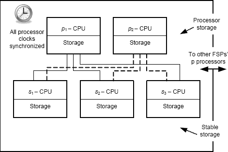
FIGURE 6.9 Basic architecture of a 1-fail-stop computer.
Each of the s processors performs a comparison to check that the k+1 outputs from the p processors are identical. If they are, then the data is part of the desired computation, and the s processors write the values into their own memory, thereby writing the data to stable storage.
If the k+1 outputs from the p processors are not identical, then some subset of the p processors has failed. In that case, the s processors do not write the data to their own memories, thereby excluding the corrupt data from stable storage. The s processors also set the status bit for their fail-stop computer to “failed” so that other computers can react as necessary. The structure used by the s processors is exactly an N-modular-redundant system as we discussed in Section 6.3.3 on page 164. The structure is used solely to detect faults in the p processors. There is no attempt to mask faults.
The computations by the s processors rely upon their having all received the same data from each of the p processors. Thus, the s processors must engage in a Byzantine agreement algorithm when they receive data from a p processor. If the values that any s processor obtains from the other 2k s processors are not identical to its own, then either one or more s processors have failed or the communication mechanism between the s processors has failed. In either event, the stable storage mechanism has failed, and the fail-stop computer has to stop. Stable storage is still operational, however, because sufficient of the s processors remain operational to maintain a majority.
6.5.6 Programming Fail-Stop Computers
The properties of fail-stop computers can now be exploited in distributed systems, because the failure semantics that we require are provided. With a little care, the programming task of fail-stop computers is fairly simple. Schlichting and Schneider defined a construct called a fault-tolerant action as the basic building block for writing applications [127].
Of course, a program executing on a fail-stop computer halts when a failure occurs. Execution can then be restarted on any remaining operational fail-stop computer that has sufficient resources. Keep in mind that the basic semantics of the fail-stop computer mean that the program will be in a well-defined and undamaged state. Although well-defined and undamaged, the state could be any state that could arise during execution.
When a program is restarted, the internal processor state and the contents of volatile storage are lost. Thus, some software is needed that can complete the state transformation that was in progress at the time of the failure and restore storage to a well-defined state. Such software is called a recovery protocol.
The syntactic structure that Schlichting and Schneider defined for the fault-tolerant action is:
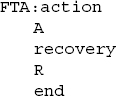
where a is the basic action and R is the recovery protocol. So the meaning of this structure is:

Clearly, a recovery protocol must have the following three properties:
• The protocol can only use information that is in stable storage.
• The protocol must be kept in stable storage because the code for a recovery protocol must be available after a failure.
• The protocol must execute correctly when started in any intermediate state that could arise during execution.
Complying with the first two properties seems fairly simple. Stable storage is stable storage after all. But the third property seems quite tricky. What we have to do is to write a recovery protocol that could essentially finish whatever the main software, the action a, was doing when the failure occurred.
The key to programming the recovery action is stable storage. The action does not write everything to stable storage, only values that need external visibility. In practice, therefore, the programming of r can be facilitated by using stable storage carefully within A.
To see this, imagine an action that only writes once to stable storage, namely, at the end of its execution. In that case, r can be exactly the same as a, because, if R is invoked, it can start the computation over again. Schlichting and Schneider refer to such an action as a restartable action.
Schlichting and Schneider present an elegant proof structure for verifying properties of fault-tolerant actions in sequence and nested within one another, thereby providing the necessary logical framework for supporting the use of the concept in real programs. Fault-tolerant actions can be composed to allow the development of large programs, and they can be nested, thereby allowing the development of complicated programs.
To further illustrate the capabilities of fault-tolerant actions executing on fail-stop computers, Schlichting and Schneider present a realistic example of a process-control system in which they show both the overall approach to programming the system on a fail-stop computer and the proof of the essential fault-tolerant properties of the software.
Key points in this chapter:
♦ Software usually has to manage the effects of degradation faults.
♦ Hardware redundancy is used to deal with degradation faults.
♦ Replication is one form of redundancy.
♦ Several platform architectures have been developed that incorporate specific forms of redundancy.
♦ An important property that is present in many architectures is statistical independence of degradation faults between redundant entities.
♦ Fail-stop computers have ideal failure semantics. Whenever a failure occurs, the computer stops at the end of the last correctly executed instruction.
Exercises
1. Explain the difference between redundancy and simple replication.
2. If a memory system uses a single parity bit for each 32-bit word, what is the smallest amount of storage within which an error can be detected? What types of error could such a parity mechanism detect?
3. Are there errors in the memory described in Exercise 2 that parity could not detect? With parity operating on 32-bit words, is it possible for the memory system to repair errors?
4. Consider the mirrored disk structure. Writes go to two separate identical disks so that there are always two copies of the data. If one of the disks fails, that disk is replaced with a new unit. The new unit is then resilvered, i.e., made to contain the same data as the surviving original unit. Develop a resilvering algorithm that could be used by the recovery software.
5. Suppose a spacecraft computer system employs dynamic redundancy and begins with two computers of which one is powered and one is not. Both computers are self-checking. When operating, each computer has a probability of failure per hour of 10-6. The probability of a processor failing immediately upon being powered up is 10-2. Assuming that the spacecraft begins flight with one computer operating and one computer powered down, derive an expression for the probability that the spacecraft computer system will operate for at least one year.
6. Explain how the four phases of fault tolerance are achieved in the dual-redundant architecture.
7. Explain how the four phases of fault tolerance are achieved in the N-modular redundant architecture.
8. Consider the dual-redundant computer architecture:
(a) What is the primary benefit that this architecture provides?
(b) List the items whose failure will be detected by this architecture.
(c) List the items whose failure will not be detected by this architecture.
9. Suppose a switched dual-redundant system is used for a business data-processing system that provides on-line sales from a Web-based catalog of products. Assuming a cold spare, summarize the major functions that the architectural support software has to perform (a) while the primary is running and (b) when the primary fails so as to get the backup functioning. Think carefully about how to handle the database, the active clients, the Web server, and whether faults are going to be masked.
10. Suppose a switched dual-redundant system is used for a business data-processing system that provides on-line sales from a Web-based catalog of products. Assuming a warm spare, summarize the major functions that the architectural support software has to perform (a) while the primary is running and (b) when the primary fails so as to get the backup functioning. Think carefully about how to handle the database, the active clients, the Web server, and whether faults are going to be masked.
11. Suppose a switched dual-redundant system is used for a business data-processing system that provides on-line sales from a Web-based catalog of products. Assuming a hot spare, summarize the major functions that the architectural support software has to perform (a) while the primary is running and (b) when the primary fails so as to get the backup functioning. Think carefully about how to handle the database, the active clients, the Web server, and whether faults are going to be masked.
12. An important claim about the concept of a fail-stop computer is that such a computer is easier to build than a reliable computer. Explain why that is the case.
13. List the three major characteristics of a fail-stop computer. For each, explain what the characteristic means in terms of the computer’s operation. For each explain how the characteristic is used in building a dependable computer system.
14. Consider the problem of developing a 2-fail-stop computer:
(a) To what does the “2” refer in the phrase “2-fail-stop”?
(b) How many p processors will be required?
(c) How many s processors will be required?
1. Actually, parity works if there is more than one changed bit as long as the number of changed bits is odd.