Chapter 15
Security in Wireless Local Area Networks
This chapter presents the security techniques used in local area networks, specifically the IEEE 802.11 standard (IEEE, 1999). After an introduction to the IEEE 802.11 wireless local area network (WLAN) standard, we discuss its security mechanisms and focus on the flawed wired-equivalent privacy (WEP), covering its intentions and shortcomings, as well as the ways to get the best protection given limited coverage; WiFi Protected Access (WPA), an interim protocol to fix the shortcomings of WEP; and 802.11i, the IEEE standard to provide strong encryption, key management, and support for authentication. We conclude by discussing virtual private networks (VPNs) and firewall protections in the context of WLANs.
15.1 Basic Idea
WLAN coverage has a radius of around 100 m typically. This covers several rooms or a small company with a few offices. Of course, actual coverage depends on where it is deployed, the material in the walls, the frequency range, other nearby radio sources, etc. WLANs offer a cheap alternative to running a wire to every office, allowing fast installation.
Many wireless access points (see below) work directly “out of the box,” requiring no configuration. The user simply plugs them into the network and a power outlet, and they work. The downside is that most devices default to being very open, with most security features disabled; these features often are overlooked for an “out of the box” installation. In addition, the users may not know that some of the security features are either limited or flawed.
IEEE 802 is the LAN/metropolitan area network (MAN) standard committee that has numerous subgroups within it. IEEE 802.11 is the WLAN standard subcommittee. And within it, there are several committees for different 802.11 standards. Each of the standards subcommittees represents different technologies or protocols. Some use different frequencies, and some use different protocols. Below we define some basic architecture concepts common to all WLANs.
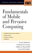
The wireless station (WS) is the remote or mobile unit. The access point (AP) or base station is the nonmobile unit that connects the wireless network into a wire-based network. The AP acts as a bridge or router and usually has some protection mechanisms built in. 802.11 networks can be organized in two different ways: infrastructure or ad hoc.
A basic service set (BSS), identified by a 6-byte string, is a network formed by an AP and the wireless stations that are associated with it.
An extended service set (ESS) is two or more BSSs that form a single logical network. As they move, wireless stations can switch seamlessly from one AP to another with no disruption of service. The APs coordinate the handoff among themselves, generally via an Ethernet connection. Figure 15.1 shows an example of two BSSs forming an ESS.
When wireless stations communicate through an AP, it is called infrastructure mode.
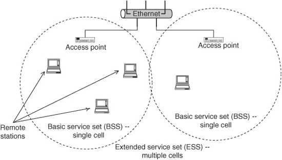
Figure 15.1 Two BSSs forming an ESS.
An independent basic service set (IBSS) is a set of wireless stations that communicate with each other directly without using an AP. In contrast to infrastructure mode, this type of communication is called ad hoc mode, and such a network is referred to as an ad hoc network. Typically, ad hoc networks form when a group of wireless stations wish to share information with each other. If all the ad hoc nodes are within range of each other, routing is trivial (i.e., broadcast). The situation becomes more complex when the ad hoc network extends beyond the reception radius of the nodes, and complex ad hoc routing protocols must be used (Perkins et al., 2003; Park and Corson, 2000; Clausen and Jacquet, 2003; Moy, 1998). Figure 15.2 shows an example of an IBSS. Wireless ad hoc routing is discussed in Chap. 12.
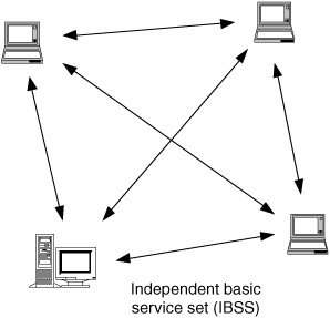
Figure 15.2 An IBSS.
A service set identifier (SSID) is a 32 byte string that identifies the name of the network, either the IBSS or the ESS.
15.2 Wireless Alphabet Soup
IEEE 802.11 was the initial protocol created in 1997 using the 2.4 GHz frequency range and supporting 1 and 2 Mbps via frequency-hopping spread spectrum (FHSS) and direct-sequence spread spectrum (DSSS). Different task groups within the 802.11 working group created and revised the 802.11 standard, e.g., support for higher data rates and the use of the 5-GHz frequency range. Each new or revised standard receives a new suffix letter. Currently, there is an “alphabet soup” of IEEE 802.11 protocols (Geier, 2002). Before discussing the most relevant protocols relating to security, we provide a brief overview of the various “802.11-something” protocols.
![]() 802.11a is a physical-layer standard that uses orthogonal frequency division multiplexing (OFDM) in the 5-GHz band, supporting speeds from 6 to 54 Mbps. 802.11a offers the highest speeds currently, although the range for the highest speeds is limited, and transmission rates drop to slower speeds beyond a short distance. 802.11a has leap-frogged over 802.11b as the fastest 802.11 technology available, having a maximum speed of 54 Mbps. However, it faces competition from 802.11g, which provides similar speeds but with better signal propagation than 802.11a and is compatible with (soon to be legacy) 802.11b cards.
802.11a is a physical-layer standard that uses orthogonal frequency division multiplexing (OFDM) in the 5-GHz band, supporting speeds from 6 to 54 Mbps. 802.11a offers the highest speeds currently, although the range for the highest speeds is limited, and transmission rates drop to slower speeds beyond a short distance. 802.11a has leap-frogged over 802.11b as the fastest 802.11 technology available, having a maximum speed of 54 Mbps. However, it faces competition from 802.11g, which provides similar speeds but with better signal propagation than 802.11a and is compatible with (soon to be legacy) 802.11b cards.
![]() 802.11b uses DSSS in the 2.4-GHz range to achieve faster speeds of 5.5 and 11 Mbps using complementary code keying (CCK) and is widely deployed. Wired-equivalent privacy (WEP) is the scheme to provide data protection and is described later in this chapter. 802.11b is currently the most widely deployed version of 802.11 cards for home and business but this will change rapidly as 802.11a and 802.11g become more widely available and less expensive.
802.11b uses DSSS in the 2.4-GHz range to achieve faster speeds of 5.5 and 11 Mbps using complementary code keying (CCK) and is widely deployed. Wired-equivalent privacy (WEP) is the scheme to provide data protection and is described later in this chapter. 802.11b is currently the most widely deployed version of 802.11 cards for home and business but this will change rapidly as 802.11a and 802.11g become more widely available and less expensive.
![]() 802.11c provides required information to ensure proper bridging operations and is used when developing APs.
802.11c provides required information to ensure proper bridging operations and is used when developing APs.
![]() 802.11d provides “global harmonization.” It defines physical-layer requirements to satisfy the different regulatory organizations in different parts of the world, e.g., United States, Japan, and Europe. This includes both the 2.4- and 5-GHz bands and only affects those developing 802.11 products.
802.11d provides “global harmonization.” It defines physical-layer requirements to satisfy the different regulatory organizations in different parts of the world, e.g., United States, Japan, and Europe. This includes both the 2.4- and 5-GHz bands and only affects those developing 802.11 products.
![]() 802.11e extends the MAC layer of 802.11 to provide quality-of-service (QoS) support for audio and video applications. These MAC-level changes will affect all 802.11 operating frequencies (i.e., 2.4 and 5 GHz) and will be backwards-compatible with the existing protocol.
802.11e extends the MAC layer of 802.11 to provide quality-of-service (QoS) support for audio and video applications. These MAC-level changes will affect all 802.11 operating frequencies (i.e., 2.4 and 5 GHz) and will be backwards-compatible with the existing protocol.
![]() 802.11f defines a standard so that different APs can communicate with each other. This “inter access point protocol” will allow wireless stations to “roam” from one AP to another. Currently, 802.11 defines no standard, so each vendor can create its own incompatible means to implement roaming.
802.11f defines a standard so that different APs can communicate with each other. This “inter access point protocol” will allow wireless stations to “roam” from one AP to another. Currently, 802.11 defines no standard, so each vendor can create its own incompatible means to implement roaming.
![]() 802.11g specifies a higher-speed extension to the 2.4-GHz band. 802.11g extends 802.11b to support up to 54 Mbps. 802.11g uses OFDM rather than DSSS. Essentially, 802.11g is designed to make 802.11b compete with the bandwidth of 802.11a.
802.11g specifies a higher-speed extension to the 2.4-GHz band. 802.11g extends 802.11b to support up to 54 Mbps. 802.11g uses OFDM rather than DSSS. Essentially, 802.11g is designed to make 802.11b compete with the bandwidth of 802.11a.
![]() 802.11h provides “spectrum-managed 802.11a” to address the requirements in Europe for use of the 5-GHz band. The functions provided include dynamic channel selection (DCS) and transmit power control (TPC), which will help to prevent any interference with satellite communications. 802.11h eventually will replace 802.11a.
802.11h provides “spectrum-managed 802.11a” to address the requirements in Europe for use of the 5-GHz band. The functions provided include dynamic channel selection (DCS) and transmit power control (TPC), which will help to prevent any interference with satellite communications. 802.11h eventually will replace 802.11a.
![]() 802.11i standardizes MAC enhancements for 802.11 security. It is designed to address the problems and shortcomings of WEP, incorporating 802.1x and stronger encryption techniques, such as the advanced encryption standard (AES), the follow-on to DES. 802.11i updates the MAC layer to provide security for all 802.11 protocols. In the meantime, many vendors are using WPA, which incorporates many features that are in the proposed 802.11i specification, even though the standard is still being developed. Section 15.5 discusses the 802.11i protocol in more detail.
802.11i standardizes MAC enhancements for 802.11 security. It is designed to address the problems and shortcomings of WEP, incorporating 802.1x and stronger encryption techniques, such as the advanced encryption standard (AES), the follow-on to DES. 802.11i updates the MAC layer to provide security for all 802.11 protocols. In the meantime, many vendors are using WPA, which incorporates many features that are in the proposed 802.11i specification, even though the standard is still being developed. Section 15.5 discusses the 802.11i protocol in more detail.
![]() 802.11j addresses 4.9- to 5.0-GHz operation in Japan (group formed on November 2002).
802.11j addresses 4.9- to 5.0-GHz operation in Japan (group formed on November 2002).
![]() 802.11k defines and exposes radio and network information to facilitate the management and maintenance of a wireless and mobile LAN. Also, it will enable new applications to be created based on this radio information, such as location-enabled services.
802.11k defines and exposes radio and network information to facilitate the management and maintenance of a wireless and mobile LAN. Also, it will enable new applications to be created based on this radio information, such as location-enabled services.
In the following sections we discuss WEP, WPA, and 802.11i, three protocols to provide protection for 802.11.
15.3 Wired-Equivalent Privacy (WEP)
WEP is the security scheme provided with 802.11b. Since wireless communication presents an easy target for casual eavesdropping, WEP was designed to raise the baseline security level to be comparable with standard wired Ethernet. Sniffing packets off a wired network requires a user to physically tap into the network; the WEP designers wanted to make sniffers go through a similar level of effort to get similar information from a wireless network. However, several severe design flaws rendered WEP virtually useless against a skilled, knowledgeable attacker. In this section we present the design goals of WEP, its data frame, and how encryption, authentication, and decryption work, and then we discuss the flaws and potential remedies. Even though WEP is considered passé, especially now that WPA and 802.11i exist, it is useful to understand what it was designed to do and what its problems are.
15.3.1 WEP goals
WEP was designed originally to support a few criteria. First, it had to be “reasonably strong.” Of course, this is a debatable point, but the goal was to raise the bar on security so that some effort must be spent to break the protection. Second, it had to be self-synchronizing. Stations must be able to resynchronize with the AP without requiring user intervention, such as a password, because the stations may go in and out of coverage frequently. Third, it must be computationally efficient so that it can be performed in either hardware or software because some processors may be low-power, low-speed devices. Fourth, it had to be exportable. Although the United States relaxed some of the encryption restrictions in January of 2000 as part of the “Wassenaar arrangement,” (Wassenaar, 2003) other countries still tightly restrict encryption technology. On the other hand, no country restricts the strength of protection used for authentication. And finally, WEP must be optional.
WEP consists of a secret key of either 40 or 104 bits (5 or 13 bytes) and an initialization vector (IV) of 24 bits. Thus the total protection, as it is sometimes called, is 64 or 128 bits (often mistakenly referred to as 64- or 128-bit “keys” even though the keys are 40 or 104 bits). The key plus the IV is used to seed an RC4-based pseudorandom-number generator (PRNG). This sends a stream of pseudorandom numbers that is XORed with the data stream to produce the ciphertext. In addition, an integrity check value (ICV) indicates if the data stream was corrupted. The ICV is a simple CRC-32 checksum. Figure 15.3 shows a block diagram of WEP encryption.
Figure 15.3 Block diagram of WEP encryption.
15.3.2 WEP data frame
The WEP data frame, shown in Fig. 15.4, consists of an IV of 4 bytes, the data or protocol data unit (PDU) of 1 or more bytes, and the ICV of 4 bytes. The IV can be further divided into 3 bytes (24 bits) of the actual initialization vector plus 1 byte that uses 2 bits to specify a key and 6 bits of padding. With the 2 bits, the device can store up to four different secret keys (recall that the keys are not transmitted but are local to the device).
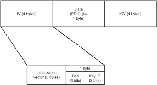
Figure 15.4 WEP data frame.
15.3.3 WEP encryption
The encryption process is shown in the block diagram in Fig. 15.3. It takes the plaintext message, the IV, and the secret key as input and produces as output a message consisting of the ciphertext message and the IV by performing the following steps:
1. Compute the ICV using CRC-32 over the plaintext message.
2. Concatenate the ICV to the plaintext message.
3. Choose a random IV and concatenate it to the secret key, and use it as input to the RC4 PRNG to produce the pseudorandom key sequence.
4. Encrypt the plaintext and the ICV by doing a bitwise XOR with the key sequence from the PRNG to produce the ciphertext.
5. Append the IV to the front of ciphertext.
15.3.4 WEP decryption
Decryption of WEP data is, more or less, just the reverse of the encryption. The algorithm takes the secret key and the message consisting of the ciphertext and ICV as input and produces the plaintext message and an error flag as output by performing the following steps:
1. Generate the key sequence k using the IV of the message.
2. Decrypt the ciphertext message by doing a bitwise XOR with k to generate the original plaintext and ICV.
3. Verify the integrity of the message by computing the ICV on plaintext, ICV’, and comparing it with the recovered ICV from step 2.
4. Trap errors, if ICV ≠ ICV’, by sending an error to the MAC management layer and back to the sending station.
15.3.5 WEP authentication
APs perform an optional challenge/response style of authentication to the wireless stations, as shown in Fig. 15.5, as follows:
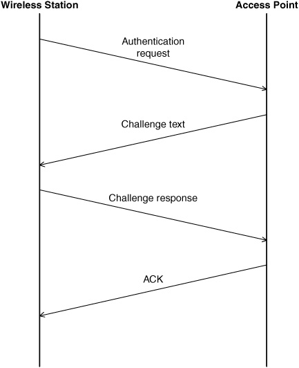
Figure 15.5 WEP authentication.
1. The wireless station (WS) sends an authentication request to the AP.
2. The AP sends a (random) challenge text T back to the WS.
3. The WS sends the challenge response, which is text T, encrypted with a shared secret key.
4. The AP sends an acknowledgment (ACK) if the response is valid and a NACK if it is invalid.
15.3.6 WEP flaws
There are a number of problems with WEP. First, from the start, it was designed to be “as good as” wired Ethernet, as opposed to providing “strong” security. WEP has been broken by various groups (Walker, 2000; Borisov et al., 2001; Fluhrer et al., 2001).
WEP provides no automated key management, and the IEEE standard does not specify any distribution mechanism. All keys must be entered manually, and typically, all wireless stations in one network use the same password. The risk that a device inadvertently shares the password increases with the number of devices sharing this password. In addition, rekeying an entire network can be an administrative nightmare. All users must be informed that the passwords (i.e., keys) are changing as of a certain date, after which they will be locked out of the network until they get the new code.
Often the same key is used for both encryption and authentication, which then ties the two functions together (i.e., if one is compromised, then both are). Another weakness in the design is the limit of the number of keys that can be used, i.e., four. Finally, using a single key for the whole network increases the chance of keystream reuse.
Collision attacks.
Keystream reuse is another problem. The more often a key is used, the easier it is to crack it. The three factors in WEP are the encryption key (IV plus secret key), the plaintext, and the ciphertext. If any two are known, the third can (eventually) be derived. The encryption key consists of the IV, which is transmitted in the clear with each packet, and the secret key, which is not transmitted.
While changing the IV with every packet is recommended, the IEEE does not specify a standard as to how often the IV must change. Reusing the IV values increases the risk of an attacker being able to subvert WEP’s protection.
The IV often is initialized to 0. This happens when the wireless card is initialized, such as when the computer is rebooted or the card is removed and inserted or possibly if the wireless station is brought out of a sleep mode. Typically, the IV is incremented by one each time, so there is a low-value bias to the IVs. If a random increment is used, a 50 percent chance of collision exists after approximately 5000 packets. If sequential increments are used, then a 24-bit IV can roll over in less than half of a day in a busy net (note that it is possible to make a net busy by inducing traffic on it, even if the encrypted data cannot be decrypted).
A keystream attack requires ciphertext from a reused keystream and partial knowledge of the plaintext. In essence, since P XOR K = C, if P (plaintext) and C (ciphertext) are known, K (key) can be computed. The known plaintext can be from predicted data (e.g., the “password:” prompt at a login) or generated by an attacker (e.g., junk mail sent to the remote machine), or in certain cases an AP may broadcast both encrypted and unencrypted data such as if the same data must be sent to a wireless station and a station on the wired network to which the AP connects. Attackers can build decryption dictionaries by observing the traffic on the network. This requires time and space, although given that tens of gigabytes of disk space are commonplace, space is no longer a serious constraint. If a known keystream is reused, then the attacker can use it to create arbitrary messages.
Forgery attacks.
Another weakness of WEP is that the ICV uses the CRC-32 as a checksum rather than a cryptographically secure hash function (see Section 13.3.1). CRC-32 is an unkeyed linear function of the message. An attacker can alter bits in the encrypted message and then alter the checksum to match the modified encrypted message without having any knowledge of the plaintext message. This means that WEP cannot (adequately) ensure message integrity.
While the RC4 algorithm generally is strong, an attacker can use the APs to decrypt the traffic. If the AP can be convinced to route traffic through the wired network, the data is sent in the clear, which provides plaintext to compare with the ciphertext transmitted by the AP. ARP cache poisoning is one method to do this, although it is not a flaw in WEP. IP redirection is another, in which the attacker modifies the encrypted packet’s address so that it is delivered to the attacker’s machine in the clear. Another attack type is reaction attacks, in which the attacker cleverly flips a few bits in a message and observes any TCP ACKs (which have a known, fixed packet size), which serves as an oracle to decrypt 1 bit of the plaintext.
Weak key attacks.
While RC4 generally is a strong algorithm, there are certain initialization vectors that produce poor results and reveal some of the bits of the plaintext, and the pattern for these IVs is well known. Many programs, such as WEPCrack (2001), can analyze a packet stream taken from AirSnort (2004) looking for the bad IVs and use it to crack the secret key. It takes around 7 GB of data, on average, to produce enough bad IVs to crack the secret key. This may be a lot of data for a home network but not that much for an active network (less than 2 hours at 11 Mbps). And an attacker could induce the traffic on a network if not enough is present. This is one of the most serious problems with WEP, because the tools to crack WEP are widely available.
Replay attacks.
Finally, WEP is vulnerable to replay attacks, in which an attacker can eavesdrop and record a sequence of packets from an authorized user and then replay the recorded sequence back to the AP, impersonating the authorized user. This type of attack could be used to authenticate an AP or even to replay a traffic stream such as an Internet purchase (imagine discovering that you bought 50 copies of a DVD instead of one).
15.3.7 WEP fixes
Before discussing the protocols to replace WEP, we briefly discuss how some of WEP’s weaknesses can be addressed.
First, to prevent reaction attacks, cryptographically secure hashes, such as MD5 and SHA-1, should be used as integrity check codes rather than a CRC. Second, better key management can increase security. Individual keys should be used per wireless station rather than per network. And changing of keys should be done, like voting in Chicago, early and often. These, of course, require changes to the protocol.
Some simple network configuration changes also can increase the protection. First, the wireless networks should be outside the firewall or at least not inside the network, possibly blocked by another firewall. In this way, if the wireless network is compromised, it does not bypass any of the security mechanisms used to protect the wired network from machines on the Internet. A VPN tunnel should be used to get from the wireless network into the protected network. Finally, a router or firewall can be configured to block outbound traffic from the wireless network to the Internet so that attackers cannot use the wireless network as a launching point for attacks on the Internet. Figure 15.6 shows an example of such a configuration. The best answer at this point is to upgrade to a better protocol. WPA is currently available and provides stronger protection than WEP, and 802.11i was ratified as a standard in late June 2004 and will be available as “WPA2.”
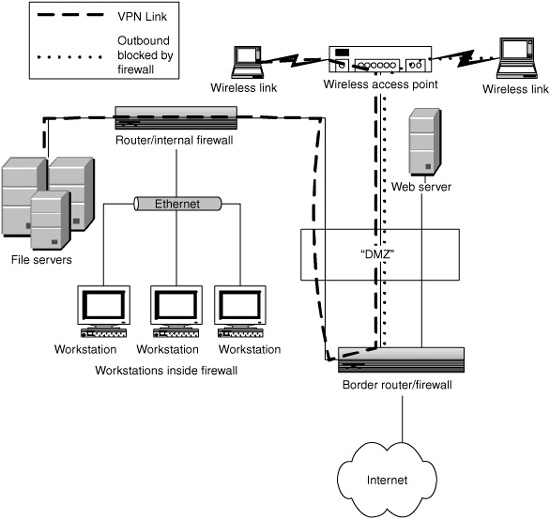
Figure 15.6 A protected wireless network configuration.
15.4 WPA
Wi-Fi protected access (WPA) was created as an interim measure to increase the security of 802.11b networks. Recognizing that WEP has too many flaws but that it will still be some time before the IEEE adopts the 802.11i protocol for security, WPA was created in 2002 by a vendor alliance (the Wi-Fi Alliance) to provide stronger protection until 802.11i arrived.
Many of the ideas in 802.11i are in WPA, and in fact, vendors expect that the upgrades will involve driver and firmware changes only.
Instead of 40-bit keys, as used in WEP, WPA uses 128-bit keys for encryption and hashing to generate new “random” keys for each use. This key protocol is called the Temporal Key Integrity Protocol (TKIP).
The Extensible Authentication Protocol (EAP) allows network administrators to select the method to use for authentication, such as bio-metric. Also, authentication is performed both ways, by the client and by the server. WEP provides only client authentication via a static password, which must be shared by all users of a network.
WPA also provides automatic key management to generate, configure, and distribute keys (Paulson, 2003).
15.5 802.11i
The 802.11i Working Group is tasked with providing security for 802.11 and addressing the weaknesses and shortcomings of WEP. 802.11i provides two layers, the lower for encryption and the higher for access control. The lower layer supports two encryption protocols, TKIP for legacy equipment and CCMP for future equipment. 802.1x, an IEEE standard for port-based network access control, provides the authentication and key management (IEEE, 2004). We discuss the two layers below (Cam-Winget et al., 2003; Walker, 2002; Eaton, 2002).
15.5.1 Encryption protocols
The Temporal Key Integrity Protocol (TKIP) and the Counter Mode with CBC-MAC Protocol (CCMP) are two encryption algorithms supported by the 802.11i standard. The standard is designed to be extensible, so new algorithms could be added, such as the Advanced Encryption Standard (AES).
TKIP.
is a short-term fix for the weaknesses of WEP that maintains compatibility with existing hardware. TKIP requires four new algorithms: a message integrity code (MIC) called “Michael”; IV sequencing, a new per-packet key construction; and a key distribution. TKIP was designed to fix the biggest flaws in WEP and provide protection against collision, weak key, forgery, and replay attacks.
Michael is a keyed hash that was designed to be a computationally low-cost MIC to run on low-power processors. It uses a 64-bit key, the source and destination address, and the plaintext data of the 802.11 frame. It partitions packets into 32-bit blocks and computes the result using shifts, XORs, and addition to create the 64-bit result. TKIP requires the keys to be changed at least once per minute and whenever there is an MIC validation error. The MIC prevents forgery attacks.
TKIP extends the 24-bit IV to 48 bits, referred to as the TKIP sequence counter (TSC). While WEP never specified how often the IV should change, TKIP requires that the TSC be updated with every packet. The TSC is constructed from the first and second bytes of the WEP IV and adds 4 extra bytes as the extended IV. The initialization vectors are now required to be a strictly increasing sequence that starts at 0 when the base key is set. When the IV reaches its maximum value, data traffic halts, and the protocol must generate a new base key and restart the IV. Because of this, any out-of-sequence packet is discarded, which prevents replay attacks.
TKIP extends the MAC protocol data unit (MPDU) by 12 bytes total, 4 for the extended IV and 8 for the MIC, and is 20 bytes longer than an unencrypted frame. WEP frames extend the frame by 8 bytes compared with an unencrypted frame.
The per-packet encryption key is generated by combining the temporal key, the transmitter address, and the TSC in a nonlinear two-phase key mixing function. The first phase uses the temporal key, the transmitter MAC address, and the 4 most significant bytes of the TSC to create an intermediate value that can be cached and used for up to 216 packets. Note that since the transmitter address is used to create the key, different hosts generate different values even using the same temporal key. The second phase takes the intermediate value and mixes it with the 2 least significant bytes of the TSC to produce the per-packet key. The second phase decorrelates the packet sequence numbers from the per-packet key, blocking weak key attacks.
TKIP uses two keys. One is the 64-bit key Michael uses, and the other is a 128-bit key used by the mixing function to create the per-packet encryption key.
802.1x authenticates the remote station after it associates with the AP. It then gets a fresh master key and distributes it.
TKIP is designed so that an attack that changes the packet sequence number also changes the per-packet encryption key so that either the traditional WEP ICV or the TKIP MIC can catch the error. The MIC makes it computationally infeasible to create an attack that alters the data in a packet. Since the MIC uses the source and destination address, packets cannot be redirected to unauthorized destinations or fake a source address.
CCMP.
The Counter Mode with CBC-MAC Protocol (CCMP) is a new encryption method defined by 802.11i and designed to provide a long-term solution to the problems in WEP without TKIP’s constraint of using only existing hardware. CBC-MAC is a method to make a Message Authentication Protocol (MAC) using cipher block chaining (CBC) (see Section 13.3.2) (NIST, 1985). CBC-MAC uses the advanced encryption standard (AES), which can support a number of different modes or algorithms. The counter mode provides privacy, whereas the CBC-MAC provides authentication and data integrity. AES is a symmetric, iterated block-mode cipher using 128-bit blocks for encryption. The encryption key length for 802.11i is set at 128 bits as well.
CCMP adds 16 bytes to the frame size compared with unencrypted packets and is identical to a TKIP frame except that there is no ICV; thus it is 4 bytes shorter than a TKIP frame.
CCMP uses a 48-bit initialization vector called the packet number (PN). Similar to TKIP, the CCMP PN is much longer than WEP and allows the same AES key to be used for the lifetime of the association. The PN serves as a sequence number that CCMP uses to prevent replay attacks.
AES, unlike TKIP, does not need any per-packet keys and thus has no per-packet key-derivation function. The same AES key is used to provide confidentiality and integrity for all the data sent during a single association. Like TKIP, CCMP uses an MIC to protect the integrity of the data. The MIC length ranges from 2 to 16 bytes and is significantly stronger than TKIP’s Michael. CCMP does not require any ICV, unlike TKIP and WEP (Cam-Wignet et al., 2002).
15.5.2 Access control via 802.1x
IEEE 802.1x is a standard for “port-based network access control” and is used by 802.11i as the mechanism to provide user authentication and encryption key distribution, both features that WEP did not provide. 802.1x is designed for both wired and wireless networks and provides a framework in which different upper-layer authentication protocols can be used. A port is any sort of controlled access and can be a router or a switch for a wired Ethernet, a modem line for a dial-up network, or a wireless AP.
802.1x defines three roles. An authenticator is the endpoint that enforces the authentication process for the other endpoint of the connection. The supplicant is the endpoint requesting access from the authenticator at the other end of the link. An authentication server (AS) is the entity that decides, based on the credentials provided by the supplicant, if the supplicant is authorized to access the services provided by the authenticator.
The AP acts as a bridge and forwards the credentials from the supplicant to the AS. Typically, RADIUS is the server used as the AS.
The authenticator defines two types of ports. An uncontrolled port allows uncontrolled exchange of data between the two ends regardless of the authorization state. A controlled port allows the exchange of data only if the current state of the port is “authorized.”
Figure 15.7 shows an example of how the authentication works. Initially, the supplicant can communicate with only the authentication server, via the authenticator’s uncontrolled port. Once the supplicant has established its authentication, the controlled port’s state is changed from “unauthorized” to “authorized,” and the supplicant then has access to the services provided by the authenticator—in this case, access to the Internet.

Figure 15.7 802.1x authentication.
The actual authentication protocol and credentials used depend on the upper-level authentication protocol used. 802.1x merely provides the framework for the exchange of data for these higher-layer protocols.
For 802.11i, two types of keys are generated. Session (or pairwise) keys are unique to each association between a client and an AP and create a private virtual port between the two. Group (or groupwise) keys are shared by all the clients connected to an AP and are used for multicast traffic.
Unlike WEP, the keys are generated dynamically, without any intervention of a network administrator. By using an authentication server, the system supports a centralized security management model as opposed to having credentials spread over many APs on a network. Since each individual remote station uses a different primary key for encryption, it becomes much harder to eavesdrop on a network or build up a dictionary of keys.
A master key, called the pairwise master key (PMK), is used to generate the lower-level keys employed by the MAC-layer encryption (for TKIP and CCMP). A RADIUS server can serve as the AS, if present. Alternatively, the network can be configured to use shared keys, pre-loaded into every device, and not use dynamic key management. This would be more typical for home use. If no AS is present, then the PMK must be entered manually into each device (the AP and the remote station). The PMK is still used to generate the session keys that are used for the actual MAC-layer data encryption.
15.6 Fixes and “Best Practices”
The 802.11 area is very dynamic, with new standards that are evolving rapidly. In fact, the area is changing so fast that any detailed technical advice we present will, in all likelihood, be out of date 6 months after it is published. And, in fact, in the time between writing and editing this book, 802.11i was ratified. Instead, we present some of the broader aspects of how to protect a system, rather than focusing on specific, ephemeral technical details.
15.6.1 Anything is better than nothing
There are various flaws in the different protection schemes and mechanisms available. However, unless the goal is to provide open access to everyone, WLANs should not be run “wide open” with no protections at all. Anything that makes it more difficult for an adversary to gain access to your network increases the level of protection.
Many access points provide MAC address—based protection. The administrator can specify a set of MAC addresses that are allowed to use the AP. This is another way to “raise the bar” for security. However, several problems exist with this approach. The size of the list of MAC addresses in the AP may be limited, and thus this might not be usable on a network with a large number of users. If the user base is relatively dynamic, it might be impractical to continually update each AP with a new list of good or bad MACs. Finally, some wireless cards allow the user to specify the MAC address, so they can be faked and are not a reliable way to block intruder access.
15.6.2 Know thine enemy
Having a realistic assessment of the capabilities and motivations of an adversary allows administrators to make informed decisions about the types and levels of protections needed. Is she a casual adversary who is looking for Internet access from the first easily available system? Or is she targeting your system in particular? How much time and money is she willing to spend trying to get at your resources? Does she care if you detect her activities? Geier (2002a) suggests several security policies for wireless networks.
15.6.3 Use whatever wireless security mechanisms are present
The best answer is to use 802.11i with 802.1x for authentication and have a separate authentication server. Smaller residential setups may not have all these components, and some installations may be stuck with using legacy hardware (even though individual wireless cards and APs are relatively inexpensive). If 802.11i, called “WPA2,” is not available, then use WPA and, literally better than nothing, WEP.
Using WEP forces the adversary to spend some, albeit a small, amount of time to break into the system. Some manufacturers have fixes, such as WEPplus, that fix some of WEP’s worse problems by not using known bad initialization vector values.
IEEE 802.1x, discussed in Section 15.5.2, provides “port-based network access control” using existing standards, including the Extensible Authentication Protocol (EAP), the Challenge Handshake Protocol (CHAP), and RADIUS (see Section 13.5.1).
WPA was the bridge to provide better security than WEP until 802.11i was finalized and products that support it become available. As of this writing, only one product supports 802.11i, but more are sure to follow shortly.
15.6.4 End-to-end VPN
Virtual private network (VPN) software allows a remote system to be part of another subnet by encapsulating the data, encrypting it, and then sending the packet to a firewall (tunneling). The firewall decrypts the data, unencapsulates them, and then retransmits them on the private network, making it appear as if the data originated locally. Similarly, data bound for the remote system from inside the private network are sent to the firewall and similarly tunneled to the remote system, at which point they are delivered as if they were a local packet. Since the data are encrypted as they pass between the nodes in the “virtual” network, eavesdroppers cannot compromise the data confidentiality.
By using VPN software or hardware, the wireless network can sit “outside” the trusted network and tunnel out of only that subnet. VPNs generally use strong encryption.
15.6.5 Firewall protection
A firewall protects networks, both wired and wireless, by serving as the delineation between a private network sitting “behind” the firewall and the public network exposed to arbitrary Internet traffic. Only certain, specified traffic enters the private network. Traffic may be permitted to, say, the mail and Web servers, whereas all other traffic is blocked. For a home installation that has no public servers, no unsolicited inbound traffic may be permitted. Usually, inbound traffic is permitted if it was initiated by an outbound connection from behind the firewall. Firewalls also can prevent inside traffic from getting out, preserving data confidentiality, as well as preventing internal machines from being used as the source of an attack against other machines on the Internet. A firewall may be a separate computer or hardware device, or it can be some form of “personal firewall” software running on the user’s machine. Hardware firewalls typically are better than personal firewalls because they serve a single purpose and run on a simplified operating system that runs only the firewall software. There are a number of products that combine the functionality of a cable modem, router, and firewall using Network Address Translation (NAT) that allow numerous home computers to share a single IP address on the Internet using the built-in Dynamic Host Configuration Protocol (DHCP) to issue the internal IP addresses. These devices are inexpensive and very convenient and as a side effect protect the users’ computers from hostile Internet traffic. Figure 15.8 shows an example of such a configuration. They may not, however, protect the wireless component of the network adequately by default. Also, some compatibility problems exist between NAT and IPsec, which is used in some VPN implementations.
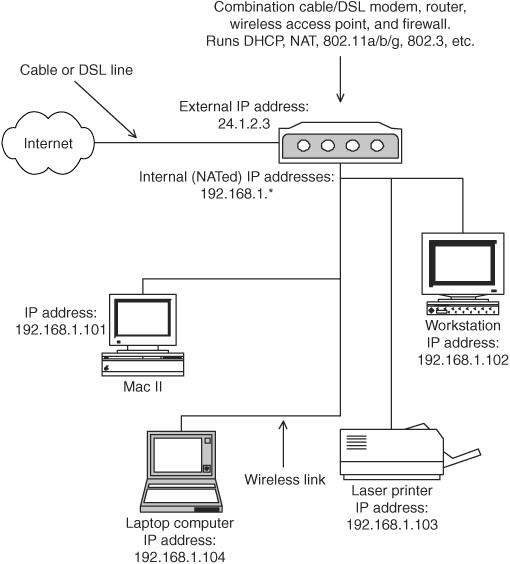
Figure 15.8 Example of a home network using NAT.
15.6.6 Use whatever else is available
SSID.
A simple first step to protect a wireless AP is to change the SSID to something other than the default. For example, it is well known that linksys and tsunami are the default SSIDs for LinkSys and Cisco APs, respectively. The less an attacker knows about the system, such as the AP hardware, the better.
Use good passwords.
All default passwords for hardware are public knowledge, so it is important to at least change the password so that it is not “default” or blank. The next step is to use a good password that is not guessed or cracked easily, e.g., avoid dictionary words.
Closed network.
In addition, the AP can be set so that it does not broadcast the SSID in the beacon frame; i.e., it is not announcing its presence continuously. This is known as a closed network (see Section 12.2.5). A wireless station must know the SSID before it can associate with the AP, as opposed to casually observing the SSID in the beacon. However, this merely obscures the SSID because it is broadcast in the clear by the wireless station when it associates with the AP and can be detected easily by a wireless packet sniffer. However, it does raise the level of protection.
Limit the radio wave propagation.
While shielding your house or living in a Faraday cage may eliminate stray radio transmissions, it is a bit extreme for home use. Moving the AP toward the center of the desired coverage area is a simple step that forces the signals to pass through more walls before reaching outside attenuating them more than if the AP sat right next to a window. Commercial wireless networks require more planning in terms of physical layout than home networks (assuming that a single AP is insufficient). Directional antennas also limit the signal propagation.
IDS.
Running an intrusion detection system (IDS) provides an additional layer of security. While an IDS does not prevent an attack, it allows the user to know that one occurred, often giving enough details to help stop the attack or prevent it from recurring. There are many freely available IDSs, such as snort (http://www.snort.org).
15.7 Summary
In this chapter we presented the basic components and operation of WLANs using the IEEE 802.11 protocol. We described the numerous 802.11 subgroups and WEP, the original security mechanism of 802.11b, specifically, its goals and functions, as well as the problems in its design. We described 802.11i, the follow-on security protocol for 802.11, as well as “best practices” for use in concert with the mechanisms in the 802.11 protocol. Chapter 16 covers wireless metropolitan area networks (WMANs), which provide Internet connectivity to the local area networks.
15.8 References
AirSnort Homepage, http://airsnort.shmoo.com/
Borisov, N., I. Goldberg, and D. Wagner, “Intercepting Mobile Communications: The Insecurity of 802.11,” in Proceedings of the 7th Annual International Conference on Mobile Computing and Networking, July 2001, Rome, Italy, http://www.isaac.cs.berkeley.edu/isaac/mobicom.pdf.
Cam-Winget N., R. Housley, D. Wagner, and J. Walker, “Security Flaws in 802.11 Data Link Protocols,” Communications of the ACM, May 2003, 46(5), pp. 35–39.
Cam-Wignet N., T. Moore, D. Stanley, and J. Walker, “IEEE 802.11i Overview,” presented at the NIST 802.11 Wireless LAN Security Workshop, Falls Church, Virginia, December 4-5, 2002, http://csrc.nist.gov/wireless/S10_802.11i%20Overview-jw1.pdf.
Clausen, T., P. Jacquet, IETF RFC 3626, “Optimized Link State Routing Protocol (OLSR),” October 2003, http://www.ietf.org/rfc/rfc3626.txt.
Dailey Paulson L., “Vendors Push Wireless LAN Security,” Computer, January, 2003, p. 28.
Eaton, D., “Diving into the 802.11i Spec: A Tutorial,” CommsDesign, November 26, 2002, http://www.commsdesign.com/design_corner/OEG20021126S0003.
Fluhrer, S., I. Mantin, and A. Shamir, “Weaknesses in the Key Scheduling Algorithm of RC4,” Lecture Notes in Computer Science, Volume 2256, 2001.
Geier J., “802.11 Alphabet Soup,” Tutorial on 80211planet web site, August 5, 2002 http://www.80211-planet.com/tutorials/article.php/1439551.
Geier J., “The Guts of WLAN Security Policy,” November 12, 2002, http://www.80211-planet.com/tutorials/article.php/1499151.
IEEE Standard 802.11, “Wireless LAN Medium Access Control (MAC) Sublayer,” 1999.
Moy, J., IETF RFC 2328, “OSPF Version 2,” April 1998, http://www.ietf.org/rfc/rfc2328.txt.
National Institute of Standards and Technology. FIPS Pub 113: “Computer Data Authentication,” May 30, 1985.
Park, V., and M.S. Corson, IETF MANET Internet Draft, draft-ietf-MANET-tora-spec-03.txt,” November 2000.
Perkins, C.E., E.M. Belding-Royer, and Samir Das, IETF RFC 3562, “Ad Hoc On Demand Routing Distance Vector (AODV) Routing,” July 2003, http://www.ietf.org/rfc/rfc3561.txt.
Walker, J., “Unsafe at any key size: an analysis of WEP encapsulation,” Tech. Rep. 03628E, IEEE 802.11 committee, March 2000, http://grouper.ieee.org/groups/802/11/Documents/DocumentHolder/0-362.zip.
Walker J., “802.11 Security Considerations and Solutions,” Intel Developer Forum, Spring 2002, http://developer.intel.com/idf.
“WEPCrack, and 802.11 Key Breaker,” http://wepcrack.sourceforge.net/.
“802.1x—Port Based Network Access Control”, http://grouper.ieee.org/groups/802/1/pages/802.1x.html.