
Chapter 10
Organic Optoelectronic Interfaces for Vision Restoration
Andrea Desii1, Maria R. Antognazza1, Fabio Benfenati2,3 and Guglielmo Lanzani1,4
1Center for Nano Science and Technology, Istituto Italiano di Tecnologia, 20133, Milan, Italy
2Center for Synaptic Neuroscience and Technology, Istituto Italiano di Tecnologia, 16132, Genoa, Italy
3University of Genova, Department of Experimental Medicine, 16132, Genova, Italy
4Politecnico di Milano, Dip.to di Fisica, Piazza Leonardo Da Vinci 32, 20133, Milano, Italy
10.1 Introduction
The eye in humans and primates is a wonderful and amazing device. Far more than a simple detector, our eye can perform advanced image processing before sending data to the central nervous system (thalamus and visual cortex), forming the most complex and sophisticated sensory systems, the visual system that is the predominant sense in higher mammals and humans. The eye evolved in about 500 M years, from a patch of light-sensitive cells exposed at the surface to the complex organ we know. Partially the brain developed in order to process the increasing volume of data the eye was collecting. Charles Darwin, the father of the evolution theory, was surprised by this outcome and apparently confessed once that it was difficult, even for him, to believe that a random process achieved that much. Yet that is what happened, and apparently not just once, because other animals quite far away from us, such as the octopus, do see in color pretty much as we do. The eye is a perfect camera with adjustable lenses, a diaphragm, and a photosensitive chip made of live neural circuits. René Descartes was the first to describe in detail the functioning of the eye as a photocamera by using a calf eye he got from a slaughterhouse in which he cut the posterior wall and replaced it with tissue paper or frosted glass. He found that the visual field refracted through the eye was projected in 2D on the rear wall of the eye (Figure 10.1).

Figure 10.1 Descartes’ representation of how the visual system perceives objects.
The eye is a fertile inspirer of technology. However, albeit many devices are clearly eye inspired, we still cannot fully reproduce it; perhaps we still do not even know exactly how it works at the level of the complex neuronal circuitry.
The optical system is rather simple, based on two main diopter surfaces, the cornea and the lens. The cornea is the transparent membrane separating the “aqueous humor” from the outside world. It performs the first reflection, corresponding to about 4% of the incident intensity, and the first refraction. Indeed, deviations from the spherical shape in the cornea may lead to vision impairment, such as astigmatism. Light rays enter the eye and reach the main refractive body, the lens. This stays just behind an adjustable diaphragm called iris delimiting the light entrance (pupil). The refractive power of the lens is finely controlled by ciliary muscles that accommodate its shape to focus the image on the retina. A young kid can neatly see an object at 10 cm from his eyes. Unfortunately this ability gets lost with time, and a 50-year-old man can typically see objects not closer than 1 m or so. The reason is the loss of elasticity in the lens that can no longer be accommodated. This defect is called presbyopia and it is easily corrected by adopting magnifying, positive lenses, the common reading glasses. On the contrary, the spectacles for short-sighted people that correct myopia use divergent lenses (indeed a myopic eye focuses on objects just in front of the retina). In his famous novel The lord of flies William Golding describes a myopic young guy who sets a fire focusing sunlight with his glasses. While the literature value is out of question here, one should note that either the young guy was affected by hypermetropia (farsightedness) and thus he was using converging lenses, or this could not happen. In another famous novel Orson Wells tells about a man who could become invisible by adjusting his refractive index in order to match that of the environment. While this, as impractical as it is, could in principle work, an unaccounted consequence would be that the invisible man would be blind, for his eye could not refract light on the retina.
The eye spatially filters out incoming rays through the small pin hole called pupil. This is an aperture controlled by light sensors connected to muscles that adjust the diameter: wide shut in the dark and narrow in strong light. This light-induced reaction is indeed exploited in testing prosthetic retina implants on animals. An important consequence of this simple geometry is that real images are formed reversed at the bottom of the eye ball. This was known since middle age and was the subject of intense study. A camera obscura, even before the advent of photography, was based on the same geometry, appreciating the neat image that forms after spatial filtering of straight light. Canaletto, the famous Venetian painter, was using this trick to fix on canvas the patterns of his majestic scenes.
The pupil is defined by the iris, a colored pattern, very beautiful and charming, that does not have any photonic function but perhaps other kind of functions, such as attracting sexual partners. Albinos have missing pigments and do not have strong colors in their iris, which looks dim red. The pupil state is controlled by the level of light intensity in the environment through several kinds of photoreceptors, besides those in the retina and responsible for vision; other pigments such as melanopsins in the ganglion cells seem involved. Melanopsin is also responsible for the circadian rhythm of the biological clock. Under jet lag this is deranged, as we all know. Staying in the sun, powering up your melanopsins, could help re-establish the balance.
Light refracted by the lens travels through the humor vitreous to reach the retina. This is a highly transparent viscous liquid, which with aging may developed thick, opaque floating bodies, perhaps made of protein aggregates. When one of these objects intercepts an image ray, we are disturbed and we see ghost spots floating in front of us. Besides this undesired effect that occurs with age or after a trauma, the transparency of the humor is amazingly high. Essentially the only losses suffered by the incoming light rays are due to the refractive surfaces, reflecting 4% each, according to the index mismatch.
After traveling through the humor vitreous, light impinges on the inner nuclear layer that contains the ganglion cells. Then, it travels through a number of neuronal layers, horizontal cells, amacrine, and bipolar cells, to finally reach the photoreceptors. This setting is surprising. All the circuitry devoted to signal processing is just in front of the detector, as if a photonic engineer would set up his cables and preamplifier just in front of the photodiode. An engineer doing this would not be considered a very smart one. However, that is what happens in the human eye and in that of most primates. The “circuitry” is so perfectly transparent that indeed such a setting does not introduce any loss. Mueller cells, stretched across the retina section, seem to work like natural optical fibers, improving light transmission through the neuronal bodies [1]. Note that there is at least one exception to the inverted retina architecture, the octopus eye. Octopuses do see colors; indeed, they are very clever animals that can also solve simple problems. They have a retina similar to ours in composition; yet the wiring is straight, not inverse. Light strikes photoreceptors, and then the electrochemical signals propagate through the neuronal layers and reach the optic nerve. Apparently, nobody knows why it is so. A possible explanation is that a short distance between the photoreceptors and the pigmented epithelium could facilitate nourishing and regeneration of the involved pigments. Owing to the curious inverse retina the optic nerve should pierce the retina to reach the brain from the inside of the eye. This brings as a consequence a blind spot in the retina where there are no photoreceptors, which occurs right at the recollection of the ganglion cell axons to form the optic nerve. Because we have two eyes and binocular vision, we do not feel this. However, using a single eye it is possible to appreciate it.
Beside the chromophore 11-cis-retinal contained in the opsins (rhodopsin, photopsins, and melanopsins), other carotenoids in the eye have the purpose of photoprotection (such as lutein and zeaxanthin). Carotenoids are compounds predominantly made by conjugated carbon and hydrogen that are quite common in the biosphere. The same pigments that give colors to fruit, vegetables, and leaves are indeed present in the eye to detect colors. Notably the molecular structure of the chromophore detecting light in our photoreceptors is almost identical to one half of the beta carotene molecule. During World War II, the British government spread the news that their counter air force was very successful because of the exceptional good sight of their soldiers, fed by a diet rich in carrots. This was not true of course. While we cannot exclude that carrots are beneficial for the eye, the real reason of the success was the discovery of the radar, a military secret at that time.
The eye is optimized for best performance at minimum cost. For instance, it has a broad field of view, about 150° in plane and 120° in vertical, but with variable space resolution in order to reduce the volume of data transmission. This is achieved by adopting the log-polar geometry, which is a space variant and size variant distribution of the photoreceptors. Active pixels are small (about 2.5 µm) and closely packed in the macula and get larger and sparse going radially to the periphery. The macula is devoted to high-resolution detection, with 1/60° angular resolution. Hawks and eagles have two maculas, in order to improve their vision. Other species such as squirrels, cats, dogs, and deer have a less dramatic regional specialization, and possess what is called an area centralis or a visual streak. Because the density of photoreceptors decreases moving from the macula to the peripheral region of the retina, the amount of data collected is also vastly reduced at the cost of resolution. This provides the lateral view, still of critical importance for controlling the space around us, yet not so rich in details that would make data transfer impractical. Having the same resolution on the whole range of view would require a brain about 104 times heavier. This smart setting of the photoreceptor has inspired the development of anthropomorphic detectors based on the log polar array. Such log-polar photodiode arrays may be used in early warning, security cameras, video surveillance systems, and robots, where the volume of the wiring connections is a serious issue [2].
The human retina contains two types of photoreceptors, rods and cones, approximately in a ratio 20 : 1 [3]. Cones are distributed radially from the fovea, a disk of a few millimeters in diameter, in a peculiar log-polar geometry. They are small (2.3 µm) and closely packed in the fovea and become sparse and larger (10 µm) in the periphery, according to the log polar geometry discussed above.
Cones are responsible, although less sensitive than rods, for daily color vision through the so-called trichromatic vision. Three subtypes of cones have been identified, namely S, M, and L, with distinct spectral responses [4], in the blue, green, and red wavelength regions respectively. However, a unique chromophore is present in all cones, namely, retinal, and the spectral tuning of the light response is achieved by modifying the local environment around the retinal molecule. During daylight activity the more sensitive rods are saturated, while under dim light they become active and cones become insensitive. Rods come in one type only, do not provide color vision, as we note in the moonlight, and have lower spatial resolution with respect to foveal vision. Because rods are not present in the fovea, a dim light can be seen better gazing at an angle. This trick was adopted by early spectroscopists, who detected weak light signals by the eye. This practice led sometimes to misconceptions such as the hypothesized form of radiation called N-rays. It was initially confirmed by many experiments, but subsequently found to be illusory [5].
10.2 Retinal Implants for Vision Restoration
Legal blindness is defined by the World Health Organization as a condition of visual acuity lower than 20/400 or visual field smaller than 20° in the better seeing eye. According to this definition, there were 39 millions of blind patients in 2010 worldwide [6]. Retinitis pigmentosa (RP) is the most common cause of inherited blindness, affecting an estimated 1.5 million people [7]. In this disease, photoreceptor cells gradually lose their function, leading to a progressive reduction of visual field and acuity, starting from the periphery. In the early stage of this disease, ganglion cells, amacrine, and horizontal and bipolar cells remain intact. There is no cure for RP, but several treatments are being tested. Implants able to substitute degenerate photoreceptors and to excite retinal output neurons can in principle restore visual perception [8]. This can be achieved by preprocessing an image recorded with an external camera to control an array of electrodes implanted in the retina, or by an intrinsically photosensitive implant able to transduce the optical energy into electric stimuli.
Retinal implants have been installed in three general configurations. In the epiretinal architecture, the device is placed on top of the inner retina, at the interface with the vitreous humor, in contact with ganglion cells. Subretinal devices are implanted where photoreceptors have been lost, between bipolar cells and pigmented epithelium. In the suprachoroidal configuration, the array is implanted between the choroid and the sclera, outside the retina. Two implants have been approved for commercialization (ARGUS II and Alpha-IMS) [9–12], some are undergoing clinical tests [13, 14], and several others are in the preclinical phase [15–18] (Figure 10.2).

Figure 10.2 Retinal prostheses based on metal/silicon electronics.
Panel (a): Mathieson et al. 2012 [18]. Reproduced with permission of Nature Publishing Group; Panel (c) Zrenner et al. 2010 [19], http://rspb.royalsocietypublishing.org/content/early/2010/11/01/rspb.2010.1747. Used under CC-BY-4.0 http://creativecommons.org/licenses/by/4.0/; Rizzo et al. 2014 [20]. Reproduced with permission of Elsevier.)
In the epiretinal ARGUS II system (Second Sight Medical Products, Sylmar, CA) the electrode array is attached to the retina with a plastic tack that penetrates the retina and is anchored in the sclera by means of tiny barbed hooks. A foil with wires leads from the electrode array to the receiver electronics located in a capsule on the eye bulb. A pocket computer with batteries translates the video image taken by an external camera mounted on a spectacle frame into electrical impulses that are sent electromagnetically by a transmitter antenna on the spectacle frame through the periorbital tissue to a receiver coil on the eye bulb positioned next to the episcleral capsule. From there, a foil with 60 wires leads directly to the 60-electrode array, which is attached to the retinal ganglion cells whose nerve fibers form the optic nerve [21]. The other commercially available implant, Alpha-IMS (Retina Implant AG, Reutlingen, Germany), contains a chip with 1500 photodiodes, amplifiers, and electrodes in each pixel, spaced 70 µm apart. Power and control signals are generated in a small box that the patient carries. A transmitter antenna behind the ear is kept in place by a magnet in a subdermal receiver box. Power and control signals are sent wirelessly to the subdermal receiver box from which a subdermal cable leads to the eyeball, ending in a thin subretinal foil. The current injected into the retina is picked up by a return electrode. The chip is positioned on a foil that carries gold wires and is surgically implanted through a flap cut into the sclera [19].
The subretinal architecture mimics more closely the anatomy of the healthy eye. The device replaces directly the depleted photoreceptors in the outermost region of the retina. This means that the integration of the device in the visual pathway is more straightforward compared with other architectures, provided that other retinal layers are intact. In the advanced stages of retinal degenerative diseases, this is seldom the case, with retinal neurons undergoing atrophy and reconnection, modifying the signaling network. If the patient’s condition allows for its implantation, a subretinal sensor can follow the natural movement of the eye and mimic more closely the physiological neural circuitry of the retina, reducing the possibility of spurious visual signaling compared to epiretinal stimulation.
The main issues with the operation of stimulating electrodes are power supply and signal control. This limits the number of electrodes that can be integrated on a single device and the potential resolution of restored vision. Each clinically tested device needs a complex surgical procedure for the installation of cables to provide power to the array. A device approaching clinical testing, the PRIMA implant (Pixium Vision, Paris, France), avoids cable implantation by projecting near-infrared (NIR) radiation on a photovoltaic device, in which silicon photodiodes in each pixel receive power and data directly through pulsed near-infrared illumination and electrically stimulate neurons [22, 23].
10.2.1 Toward an Organic Artificial Retina
All these metal–silicon artificial devices still have to face and solve major common problems: need for power supply, scarce biocompatibility, low compliance, complexity of the fabrication process, electrode number, size and geometry, high impedance levels, resistive currents, and pronounced heat production, which is very detrimental to the retinal tissue. Organic semiconductors, however, do have specific advantages in this application. They comprise single crystals, small molecules, and conjugated polymers (CPs). They are based on conjugated carbon atoms, similar to natural molecules (and to the retinal molecule in particular), thereby bearing an intrinsic affinity for biological systems. They have π-electrons delocalized along their backbone that induce strong coupling with light; indeed, many optically active compounds in nature are based on conjugated carbons (e.g., carotenoids and chlorophylls in light harvesting complexes) and the most successful applications of organic semiconductors deal with light (e.g., organic light-emitting diodes, displays, and lightning). Since their optical band gap is in the visible range and can be properly engineered by chemical tailoring, CPs are intrinsically sensitive to visible light, and a proper selection of materials allows the realization of trichromatic sensing [24]. In particular, CPs combine the outstanding mechanical properties and simple processing technologies typical of plastic with the optoelectronic properties of semiconductors. Because of their inherent softness and low degree of toxicity, they represent excellent biocompatible materials for biological applications, both in vitro and in vivo, allowing for a more intimate interface with a liquid bioenvironment. Finally, CPs are able to conduct both electrons and ions and form stable interfaces with water, opening a new communication channel between electronics and biology (Figure 10.3). The way to an organic artificial retina passes through the study of the interaction of CPs with electrically excitable biological systems. In the next section, optically activated electrical excitation of single neurons and the performance of CPs on explanted blind retinas will be discussed. These are fundamental developmental steps for the implantation of CP-based devices in animal models.

Figure 10.3 Hybrid solid–liquid cells. (a) Chemical structures of regioregular poly(3-hexylthiophene-2,5-diyl) (rr-P3HT) and phenyl-C61-butyric-acid-methyl ester (PCBM). (b) Scheme of the hybrid solid–liquid cell for modulated photocurrent spectroscopy. (c) Spectral response of the systems ITO/rr-P3HT:PCBM/NaCl/Gold (blue line and triangles) and ITO/rr-P3HT:PCBM/Ringer/Gold (red line and squares), with the saline solutions working as ionic cathodes, recorded after 12 days of immersion in minimum essential medium. Typical spectral response (in arbitrary units for direct comparison with present results) of a conventional, solid-state solar cell (ITO/rr-P3HT:PCBM (1 : 1)/Al) is reported as a reference (dashed, gray line).
Ghezzi et al. 2011 [25]. Reproduced with permission of Nature Publishing Group.). (d) Schematic of an 8 × 8 multielectrode array (MEA) with 60 indium tin oxide (ITO) electrodes coated with a BHJ layer. Aqueous KCl solution (100 mM) is held on top of the polymer film. (e) Various wavelengths of the visible spectrum are dispersed onto the array. (f) Photovoltage response of the ITO|BHJ|aq device as a function of various λ values of the visible spectrum.
Gautam et al. 2011 [26]. Reproduced with permission of American Chemical Society.)
10.2.2 Cellular Photostimulation Mediated by Molecular Materials
Optical stimulation of excitable cells is emerging as an alternative to electrical and chemical stimulation methods, especially due to a higher degree of temporal and spatial resolution [27–29]. Light stimulation can be induced directly with high-intensity pulsed laser or IR illumination, owing to processes such as membrane poration, heating, and excitation of endogenous chromophores [30–34]. In most studies, however, cell stimulation is induced by the introduction of exogenous chromophores, such as caged compounds based on γ-aminobutyric acid (GABA) and glutamate, which can be activated upon irradiation [35]. One of the most successful approaches is optogenetics, in which cells express a light-sensitive protein, used for the modulation of biological activity [36–38]. The expression of light-gated ion channels and pumps allows the control of cell excitation and inhibition [39, 40].
Another way to optically excite biological systems is to exploit the optoelectronic properties of semiconducting materials [41, 42]. It has been demonstrated that the photocurrent generated by a silicon chip kept at reverse bias is able to stimulate electrical activity in neurons grown on top of it. Pappas et al. obtained similar results by using a thin film of semiconducting HgTe nanoparticles [43].
10.2.3 Optoelectronic Organic Membranes for Cell Stimulation
Only recently organic semiconductors have been proposed as photoactive materials in biointerfaces. Cells live in an ion-rich watery environment. Ionic transport is a key phenomenon in cell metabolism and signaling, mediated by pumps and ion channels. Thus, the use of organic photodetectors in medical and biological applications raises an important issue in the design of bio-organic interfaces: the intimate contact between the organic semiconductor and the physiological liquid environment. In addition, the liquid electrolyte challenges organic device survival, as degradation of the metal electrode is greatly accelerated in a liquid environment. A solution to the latter problem is the realization of devices in which the metal electrode is substituted by aqueous saline solutions. It is clear that hybrid solid–liquid interfaces play a key role in bio-organic electronics, and a number of studies aiming at characterizing such an interface have been reported [44–46]. Aqueous solutions have been extensively used as gate electrodes in field-effect transistors for biological sensing, demonstrating, in some cases, optimal electronic performances and outstanding biocompatibility properties.
The biocompatibility of organic semiconductors, both molecular and polymeric materials, has been reported in various studies. Biscarini and coworkers demonstrated the adhesion and growth of primary rat neurons on pentacene thin films [47]. While cells rapidly aggregated into large assemblies on the bare semiconductor, when pentacene was coated with adhesion molecules (e.g., laminin or poly-l-lysine) the growth of neurons was comparable to that observed on glass substrates coated with the same molecules. Moreover, pentacene proved to be a suitable substrate also for the adhesion and differentiation of neural stem cells. Studies on the biocompatibility of polymeric semiconductors were first performed by Scarpa et al. with mouse fibroblasts grown onto poly(3-hexylthiophene-2,5-diyl) films [48]. Also in this case, the bare film proved to be a poor substrate for cellular cultures; however, after treatment with adhesion proteins or oxygen plasma, cell adhesion and growth significantly increased. Successively, Ghezzi et al. prepared cultures of primary rat hippocampal neurons onto both P3HT:PCBM blends and pure P3HT films coated with poly-l-lysine, observing no difference in vitality and spontaneous electrical activity (action potential firing, synaptic currents) up to 28 days in vitro with respect to cultures on control substrates [25].
Several of these organic (macro)molecules have been demonstrated to work as active layers in direct contact with liquid electrolytes [26, 49–51]. In these examples, the device structure comprises an anodic contact (usually ITO) covered by the organic photosensitive layer and a saline electrolyte. Reported materials include regioregular P3HT (rr-P3HT), poly[N-90-heptadecanyl-2,7-carbazole-alt-5,5-(40,70-di-2-thienyl-20,10,30-benzothiadiazole)] (PCDTBT), P3OT, poly(9,9-dioctylfluorene-co-benzothiadiazole) (F8BT), poly[2-methoxy-5-(2-ethylhexyloxy)-1,4-phenylenevinylene] (MEH-PPV), poly[2-methoxy-5-(30,70-dimethyloctyloxy)-1,4-phenylene vinylene] (MDMO-PPV), poly [2,6-(4,4-bis-(2-ethylhexyl)-4H-cyclopenta[2,1-b:3,4-b0]dithiophene)-alt-4,7-(2,1,3-benzothiadiazole)] (PCPDTBT) as photoactive polymers, and poly {[N,N0-bis(2-octyldodecyl)-naphthalene-1,4,5,8-bis(dicarboximide)-2,6-diyl]-alt-5,50-(2,20-bithiophene)} (N2200) and PCBM as electron acceptors. Various electrolytes can be used for the saline solution; for direct interfacing to living cells, sodium chloride is the most interesting case, since it represents the most abundant cation of the biological extracellular fluids and of any cell culture medium. Indeed, the same device configuration shows the generation of a photocurrent in the presence of common culturing and buffering media. The main difference between hybrid and conventional organic photodetectors is related to interface phenomena between the polymer film and the electrolyte: in the hybrid device the conductance type changes from mainly electronic to ionic; in the solid-state cell, the mechanism is that of a standard Schottky barrier photodiode. The equilibrium conditions at the interface are qualitatively similar: chemical potential (Fermi level) is equalized by charge transport across the interface. Yet, the microscopic setting is dramatically different. In the solid device charge carrier migration leads to space charge separation across the interface, generating local electric fields that cause band bending. In the hybrid system, ion adsorption at the surface competes with charge transfer, also mediated by chemical reactions. A dipole layer forms at the surface, while a diffused ion layer spreads in the solution (i.e., Helmholtz layer).
In 2011, our group demonstrated that an organic photovoltaic blend (namely P3HT:PCBM) coated on a transparent ITO conducting layer is able to elicit electrical activity in primary neurons grown on top of it upon photostimulation (Figure 10.4) [25]. By recording membrane potentials by means of whole-cell patch-clamp under current-clamp configuration, it was shown that a 20 ms green light pulse (532 nm, 10–15 mW mm−2) (where P3HT is strongly absorbing) evoked the generation of action potentials in neurons with great reproducibility. The response time was very rapid (around 10 ms to reach the peak of the spike) and the photostimulation process was highly spatially selective: if the light spot was moved just outside the cell body, no significant activity could be elicited in the neuron. The photophysics of the photovoltaic blend used in this study suggests a role for bulk charge photogeneration in the excitation mechanism. However, it has been found that the same transduction process of light pulses into neuronal electrical activity is obtained by using a neat P3HT film (deposited on ITO) [52]. This observation indicates that the functioning of such a hybrid interface can be quite different from that of conventional organic photovoltaic devices (P3HT only solar cells have much lower efficiencies than bulk heterojunction cells with PCBM) and that faradaic currents, injected in the cleft between the device and the neuron, are not relevant. Indeed, a large body of experimental evidence suggests the presence of a capacitive coupling between the organic layer and the neuron grown on top of it. The proposed model assumes that upon photon absorption, positive charges generated in the proximity of the ITO electrode migrate into it, leaving the polymer layer negatively charged. The negative surface causes a rearrangement of the ions in the cleft, subtracting positive charges from the extracellular face of the facing cell membrane, eventually resulting in the depolarization of the cell membrane.
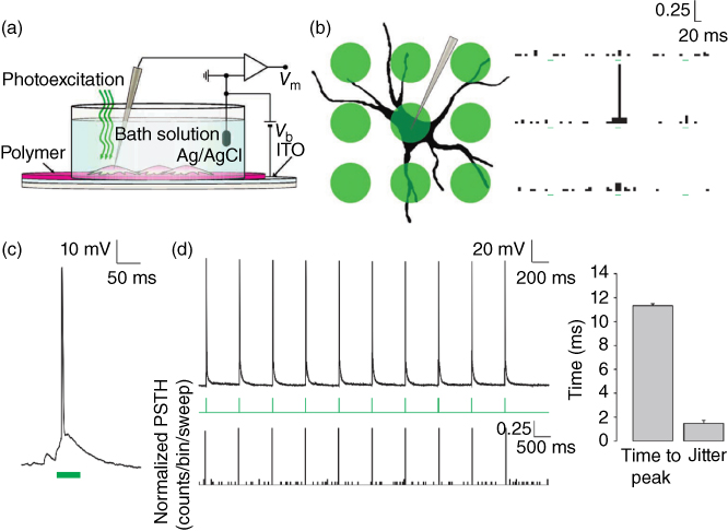
Figure 10.4 Optical stimulation of neurons cultured onto an organic optoelectronic device. (a) Scheme of the photosensing interface, with the neuronal network grown on top of the polymer active layer during patch-clamp recordings. (b) Spatial properties of the photostimulating interface. A grid of nine spots (diameter 20 µm, spacing 30 µm) was overlaid on a patched neuron and spikes were counted. Peristimulus time histograms (PSTHs) arranged in a similar grid represent the spike counts normalized for the total number of sweeps in all recorded neurons (bins 10 ms). Each histogram represents the count of the spikes recorded at the soma by the corresponding stimulation spot. (c) Action potential generation in response to a photostimulation pulse (50 ms). (d) Example of spike train generated with 20 ms pulses repeated at 1 Hz (upper panel). PSTH count was computed and normalized by considering spike trains in all recorded neurons (bottom panel; bins 20 ms). The right plot shows the latency to the spike peak with respect to the light onset computed by averaging all spikes in the train obtained from all recorded neurons and the jitter calculated as the s.d. of spike latencies measured across all recorded neurons.
(Ghezzi et al. 2011 [25]. Reproduced with permission of Nature Publishing Group.)
Photostimulation mediated by conjugated polymer membranes was demonstrated in other nonexcitable cells, namely, neocortical astrocytes and human embryonic kidney (HEK-293) cells [53, 54]. Photoexcitation of P3HT induces a significant depolarization of the astroglial resting membrane potential: the effect is associated to an increase in whole-cell conductance at negative potentials. The magnitude of the evoked inward current density is proportional to the illumination intensity. Biophysical and pharmacological characterization suggests that the ion channel mediating the phototransduction mechanism is a chloride channel, the ClC-2 channel. In the stimulation of HEK-293 cells, on top of the capacitive charging of the polymer interface, two concomitant mechanisms were identified and characterized, leading to membrane depolarization and hyperpolarization, both mediated by a photothermal effect.
The high spatial and temporal resolution of the photoexcitation, together with the good biocompatibility properties demonstrated for the organic semiconductors, opens the way to potential applications in the field of retinal prosthetics.
10.2.4 Photoelectrical Stimulation of Explanted Blind Retinas Mediated by Optoelectronic Thin Membranes
The phenomenon of cell stimulation by polymer photoexcitation (CSP) seems naturally fitting for the artificial retina application. The goal here is to restore photosensitivity in retinas whose natural photoreceptors are damaged or lost. The retinal photoreceptors, however, are in contact with bipolar cells, and both photoreceptors and bipolar cells behave quite differently from primary brain neurons in that they do not develop action potentials, and glutamate stored in synaptic vesicles is continuously released as a function of the membrane potential from a highly specialized structure called the ribbon synapse. In addition, the released glutamate is recognized by distinct receptors that alternatively mediate excitatory or inhibitory effects on postsynaptic bipolar cells [55]. For the high complexity of retinal physiology, success of the polymer approach, as demonstrated for neurons, in restoring light sensitivity in retinas depleted of photoreceptors is thus not granted. Nevertheless, very recently Ghezzi et al. reported that such a bio-organic interface is capable of restoring light sensitivity in blind retinas ex vivo [52]. Acutely dissected blind retinas from albino rats subjected to light-induced photoreceptor damage were placed on P3HT-coated glass:ITO substrates with the external layers in contact with the polymer. A 10 ms light pulse (4 mW mm−2) was able to stimulate the firing of retinal ganglion cells (measured by extracellular recordings in the ganglion cell layer) to levels indistinguishable from those of healthy retinas of control rats, while no significant activity correlated to the light stimulus could be recorded in blind retinas placed on substrates lacking the polymeric layer (Figure 10.5c,d). The analysis of the temporal and pharmacological characteristics of the excitation proved that ganglion cell spiking was mediated by the activation of the external cell layer in contact with the polymer. Dose–response measurements revealed a threshold intensity for photostimulation of about 0.3 mW mm−2, closely matching the range of retinal irradiance during outdoor activity in the sun (0.1–10 mW mm−2).
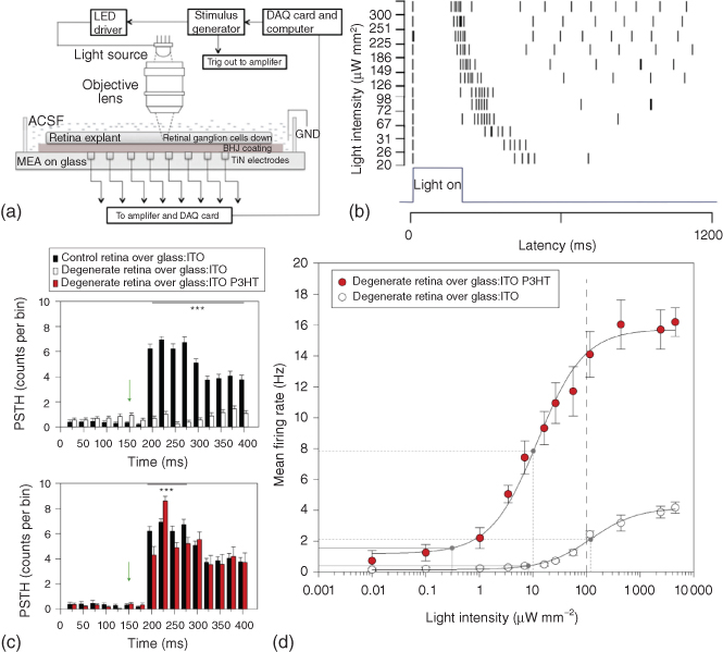
Figure 10.5 Stimulation of blind retina with organic optoelectronic membranes. (a) Schematic of the experimental setup for simultaneous photoexcitation of the BHJ layer and recording of the retinal activity using an MEA. (b) A raster plot of elicited action potentials with increasing light intensities. Each marker corresponding to a specific intensity represents an action potential.
(Gautam et al. 2014 [56]. Reproduced with permission of John Wiley and Sons.). (c), Comparison of mean PSTHs (bin, 25 ms) obtained from control retinas on glass:ITO (black bars), degenerate retinas on glass:ITO (open bars), and degenerate retinas on P3HT-coated glass:ITO (red bars) in response to light illumination (10 ms, 4 mW mm−2; green arrow). (d) Dose–response analysis of the mean firing rate versus light intensity performed in degenerate retinas over P3HT-coated glass:ITO (red dots) or glass:ITO alone (open dots). Mean firing rates were calculated in a window of 250 ms after the light pulse. Dashed line: computed maximum permissible radiant power for chronic exposure (see Methods). Dose–response curves were fitted using a sigmoidal dose–response model. Solid gray lines represent the response threshold (10% of the maximal response), and dotted gray lines represent the average half-maximum effective dose (ED50) calculated from the fitting procedure (12.11 and 120.78 mW mm−2, respectively).
Ghezzi et al. 2013 [52]. Reproduced with permission of Nature Publishing Group.)
In a study by Gautam et al., bulk heterojunctions (BHJs) based on conjugated polymers (P3HT:N2200) were able to provide visual cues to a blind, early-stage chick retina [56]. The explanted tissue was interfaced epiretinally with a BHJ-coated microelectrode array (MEA) and exposed to light pulses of various intensity (20–300 μW mm−2), wavelength (410, 533, 570 nm), and repetition rate (1–0.01 Hz) (Figure 10.5a,b). The photoelectric signals initiated by the BHJ layer evoked neuronal activity in the ganglion cells, with features resembling the natural response of the retina to light stimulation. The average number of evoked spikes increased with the light intensity, while the average response latency decreased. Bareket et al. used semiconductor membranes based on carbon nanotubes and CdSe/CdS semiconductor nanocrystals (SCNC) to photostimulate blind chick retinas [57]. Even if the films are not organic, they share with conjugated polymers most of the advantages over inorganic, silicon-based devices, one important exception being biocompatibility. To fit in vivo applications, the system must retain its inertness and its performance without causing toxic effects. SCNCs, especially free in solution, may induce adverse cytotoxicity effects [58, 59]. Nevertheless, the device was able to elicit ganglion cell spiking in an epiretinal configuration upon irradiation (405 nm).
The reported results demonstrate that organic semiconductors can be a valid alternative to the more traditional devices used for retinal implants, mostly based on inorganic semiconductors and/or metallic electrodes.
10.3 Perspectives
The implantation of artificial vision devices in man is a testament to the huge developments made in ophthalmology, microelectronics, biomedical engineering, and applied physics in the last decades. However, research is struggling to understand if the bionic eye can really improve the quality of life of patients. Devices based on electrode arrays fabricated using silicon microtechnology are facing issues in interfacing with the biological environment, because of heating, invasive surgical procedures, and limits in the resolution of the prostheses. All these reasons have strongly limited the success of these metal-silicon-based prostheses. Although the coupling mechanism between neural cells and the semiconducting polymer is still only partially understood, its potential impact is clear-cut. The advantages offered by organic semiconductors are manifold, and rely on material softness, reduced invasivity, very low toxicity, and enhanced biocompatibility, lack of need for external biasing, very limited and spatially confined heat production, and reduced redox reactions at the interfaces, as a consequence of the capacitive-like coupling between the artificial and the natural tissue. Another major advantage is the spatial confinement of the stimulation, which could in principle improve the limited resolution of traditional implants. There are however many open issues, regarding in particular the long-term stability of the polymeric material, the tolerability over prolonged time in vivo, and the optimization of the device response. Chemical engineering of substrates, anodic contacts, active materials, and encapsulation layers is expected to play a central role in the future development and implementation of organic-based retinal implants. To address these issues, research groups working on organic-based, flexible optoelectonic membranes for vision restoration are moving to preclinical testing to assess biocompatibility, stability, and function of prototype implantable devices. The work done in this area with metal- and silicon-based artificial retinas is providing invaluable cues for the implementation of surgical procedures, the choice of suitable animal models, and the evaluation of function and compliance of organic-based sensors.
References
- 1 Franze, K. , Grosche, J. , Skatchkov, S.N. et al. (2007) Müller cells are living optical fibers in the vertebrate retina. Proc. Natl. Acad. Sci. U.S.A. , 104 (20), 8287–8292.
- 2 Berton, F. , Sandini, G. , and Metta, G. (2006) Anthropomorphic visual sensors, in Encyclopedia of Sensors (eds C.A. Grimes , E.C. Dickey , and M.V. Pishko ), ASP, American Scientific Publication, Stevenson Ranch, CA.
- 3 Kolb, H. Facts and Figures Concerning the Human Retina. In Webvision: The Organization of the Retina and Visual System; Kolb, H. , Fernandez, E. , Nelson, R. , Eds.; University of Utah Health Sciences Center: Salt Lake City (UT), 1995.
- 4 Bowmaker, J.K. and Dartnall, H.J. (1980) Visual pigments of rods and cones in a human retina. J. Physiol. , 298, 501–511.
- 5 Lagemann, R.T. (1977) New light on old rays: N rays. Am. J. Phys , 45 (3), 281–284.
- 6 Pascolini, D. and Mariotti, S.P. (2011) Global estimates of visual impairment: 2010. Br. J. Ophthalmol. , 96, 614–618.
- 7 Parmeggiani, F. (2011) Clinics, epidemiology and genetics of retinitis pigmentosa. Curr. Genomics , 12 (4), 236–237.
- 8 Zrenner, E. (2002) Will retinal implants restore vision? Science , 295 (5557), 1022–1025.
- 9 Humayun, M.S. , Dorn, J.D. , Ahuja, A.K. et al. (2009) Preliminary 6 month results from the Argus™ II epiretinal prosthesis feasibility study. Annual International Conference of the IEEE Engineering in Medicine and Biology Society 2009 , pp. 4566–4568.
- 10 Ahuja, A.K. , Dorn, J.D. , Caspi, A. et al. (2011) Blind subjects implanted with the Argus II retinal prosthesis are able to improve performance in a spatial-motor task. Br. J. Ophthalmol. , 95 (4), 539–543.
- 11 Rothermel, A. , Liu, L. , Aryan, N.P. et al. (2009) A CMOS chip with active pixel array and specific test features for subretinal implantation. IEEE J. Solid-State Circuits , 44 (1), 290–300.
- 12 Stingl, K. , Bartz-Schmidt, K.U. , Besch, D. et al. (2013) Artificial vision with wirelessly powered subretinal electronic implant alpha-IMS. Proc. R. Soc. London, Ser. B , 280 (1757), 20130077.
- 13 Keserü, M. , Feucht, M. , Bornfeld, N. et al. (2012) Acute electrical stimulation of the human retina with an epiretinal electrode array. Acta Ophthalmol. (Copenh.) , 90 (1), e1–e8.
- 14 Morimoto, T. , Kamei, M. , Nishida, K. et al. (2011) Chronic implantation of newly developed suprachoroidal-transretinal stimulation prosthesis in dogs. Invest. Ophthalmol. Vis. Sci. , 52 (9), 6785–6792.
- 15 Zhou, J.A. , Woo, S.J. , Park, S.I. et al. (2008) A suprachoroidal electrical retinal stimulator design for long-term animal experiments and in vivo assessment of its feasibility and biocompatibility in rabbits. BioMed Res. Int. , 2008, e547428.
- 16 Shire, D.B. , Kelly, S.K. , Chen, J. et al. (2009) Development and implantation of a minimally invasive wireless subretinal neurostimulator. IEEE Trans. Biomed. Eng. , 56 (10), 2502–2511.
- 17 Shivdasani, M.N. , Luu, C.D. , Cicione, R. et al. (2010) Evaluation of stimulus parameters and electrode geometry for an effective suprachoroidal retinal prosthesis. J. Neural Eng. , 7 (3), 036008.
- 18 Mathieson, K. , Loudin, J. , Goetz, G. et al. (2012) Photovoltaic retinal prosthesis with high pixel density. Nat. Photonics , 6 (6), 391–397.
- 19 Zrenner, E. , Bartz-Schmidt, K.U. , Benav, H. et al. (2010) Subretinal electronic chips allow blind patients to read letters and combine them to words. Proc. R. Soc. London, Ser. B , 278, 1489–1497.
- 20 Rizzo, S. , Belting, C. , Cinelli, L. et al. (2014) The Argus II retinal prosthesis: 12-month outcomes from a single-study center. Am. J. Ophthalmol. , 157 (6), 1282–1290.
- 21 Humayun, M.S. , Dorn, J.D. , da Cruz, L. et al. (2012) Interim results from the international trial of second sight’s visual prosthesis. Ophthalmology , 119 (4), 779–788.
- 22 Mandel, Y. , Goetz, G. , Lavinsky, D. et al. (2013) Cortical responses elicited by photovoltaic subretinal prostheses exhibit similarities to visually evoked potentials. Nat. Commun., 4, 1980.
- 23 Lorach, H. , Goetz, G. , Smith, R. et al. (2015) Photovoltaic restoration of sight with high visual acuity. Nat. Med. , 21 (5), 476–482.
- 24 Antognazza, M.R. , Scherf, U. , Monti, P. , and Lanzani, G. (2007) Organic-based tristimuli colorimeter. Appl. Phys. Lett. , 90 (16), 163509.
- 25 Ghezzi, D. , Antognazza, M.R. , Dal Maschio, M. et al. (2011) A hybrid bioorganic interface for neuronal photoactivation. Nat. Commun. , 2, 166.
- 26 Gautam, V. , Bag, M. , and Narayan, K.S. (2011) Single-pixel, single-layer polymer device as a tricolor sensor with signals mimicking natural photoreceptors. J. Am. Chem. Soc. , 133 (44), 17942–17949.
- 27 Callaway, E.M. and Yuste, R. (2002) Stimulating neurons with light. Curr. Opin. Neurobiol. , 12 (5), 587–592.
- 28 Sjulson, L. and Miesenböck, G. (2008) Photocontrol of neural activity: biophysical mechanisms and performance in vivo. Chem. Rev. , 108 (5), 1588–1602.
- 29 Szobota, S. and Isacoff, E.Y. (2010) Optical control of neuronal activity. Annu. Rev. Biophys. , 39 (1), 329–348.
- 30 Fork, R.L. (1971) Laser stimulation of nerve cells in aplysia. Science , 171 (3974), 907–908.
- 31 Smith, N.I. , Iwanaga, S. , Beppu, T. et al. (2006) Photostimulation of two types of Ca2+ waves in rat pheochromocytoma PC12 cells by ultrashort pulsed near-infrared laser irradiation. Laser Phys. Lett. , 3 (3), 154–161.
- 32 Hirase, H. , Nikolenko, V. , Goldberg, J.H. , and Yuste, R. (2002) Multiphoton stimulation of neurons. J. Neurobiol. , 51 (3), 237–247.
- 33 Uzdensky, A.B. and Savransky, V.V. (1997) Single neuron response to pulse-periodic laser microirradiation. Action spectra and two-photon effect. J. Photochem. Photobiol., B , 39 (3), 224–228.
- 34 Shapiro, M.G. , Homma, K. , Villarreal, S. et al. (2012) Infrared light excites cells by changing their electrical capacitance. Nat. Commun. , 3, 736.
- 35 Ellis-Davies, G.C.R. (2007) Caged compounds: photorelease technology for control of cellular chemistry and physiology. Nat. Methods , 4 (8), 619–628.
- 36 Fenno, L. , Yizhar, O. , and Deisseroth, K. (2011) The development and application of optogenetics. Annu. Rev. Neurosci. , 34 (1), 389–412.
- 37 Hegemann, P. and Möglich, A. (2011) Channelrhodopsin engineering and exploration of new optogenetic tools. Nat. Methods , 8 (1), 39–42.
- 38 Kotov, N.A. , Winter, J.O. , Clements, I.P. et al. (2009) Nanomaterials for Neural Interfaces. Adv. Mater. , 21 (40), 3970–4004.
- 39 Zhang, F. , Wang, L.-P. , Brauner, M. et al. (2007) Multimodal fast optical interrogation of neural circuitry. Nature , 446 (7136), 633–639.
- 40 Boyden, E.S. , Zhang, F. , Bamberg, E. et al. (2005) Millisecond-timescale, genetically targeted optical control of neural activity. Nat. Neurosci. , 8 (9), 1263–1268.
- 41 Fromherz, P. (2002) Electrical interfacing of nerve cells and semiconductor chips. ChemPhysChem , 3 (3), 276–284.
- 42 Fromherz, P. (2008) Joining microelectronics and microionics: nerve cells and brain tissue on semiconductor chips. Solid-State Electron. , 52 (9), 1364–1373.
- 43 Pappas, T.C. , Wickramanyake, W.M.S. , Jan, E. et al. (2007) Nanoscale engineering of a cellular interface with semiconductor nanoparticle films for photoelectric stimulation of neurons. Nano Lett. , 7 (2), 513–519.
- 44 Cramer, T. , Steinbrecher, T. , Koslowski, T. et al. (2009) Water-induced polaron formation at the pentacene surface: quantum mechanical molecular mechanics simulations. Phys. Rev. B , 79 (15), 155316.
- 45 Eisenthal, K.B. (1996) Liquid interfaces probed by second-harmonic and sum-frequency spectroscopy. Chem. Rev. , 96 (4), 1343–1360.
- 46 Svennersten, K. , Larsson, K.C. , Berggren, M. , and Richter-Dahlfors, A. (2011) Organic bioelectronics in nanomedicine. Biochim. Biophys. Acta – Gen. Subj. , 1810 (3), 276–285.
- 47 Bystrenova, E. , Jelitai, M. , Tonazzini, I. et al. (2008) Neural networks grown on organic semiconductors. Adv. Funct. Mater. , 18 (12), 1751–1756.
- 48 Scarpa, G. , Idzko, A.-L. , Götz, S. , and Thalhammer, S. (2010) Biocompatibility studies of functionalized regioregular poly(3-hexylthiophene) layers for sensing applications. Macromol. Biosci. , 10 (4), 378–383.
- 49 Antognazza, M.R. , Ghezzi, D. , Musitelli, D. et al. (2009) A hybrid solid–liquid polymer photodiode for the bioenvironment. Appl. Phys. Lett. , 94 (24), 243501.
- 50 Lanzarini, E. , Antognazza, M.R. , Biso, M. et al. (2012) Polymer-based photocatalytic hydrogen generation. J. Phys. Chem. C , 116 (20), 10944–10949.
- 51 Gautam, V. , Bag, M. , and Narayan, K.S. (2010) Dynamics of bulk polymer heterostructure/electrolyte devices. J. Phys. Chem. Lett. , 1 (22), 3277–3282.
- 52 Ghezzi, D. , Antognazza, M.R. , Maccarone, R. et al. (2013) A polymer optoelectronic interface restores light sensitivity in blind rat retinas. Nat. Photonics , 7 (5), 400–406.
- 53 Benfenati, V. , Martino, N. , Antognazza, M.R. et al. (2014) Photostimulation of whole-cell conductance in primary rat neocortical astrocytes mediated by organic semiconducting thin films. Adv. Healthc. Mater. , 3 (3), 392–399.
- 54 Martino, N. , Feyen, P. , Porro, M. et al. (2015) Photothermal cellular stimulation in functional bio-polymer interfaces. Sci. Rep. , 5, 8911.
- 55 Wässle, H. (2004) Parallel processing in the mammalian retina. Nat. Rev. Neurosci. , 5 (10), 747–757.
- 56 Gautam, V. , Rand, D. , Hanein, Y. , and Narayan, K.S. (2014) A polymer optoelectronic interface provides visual cues to a blind retina. Adv. Mater. , 26 (11), 1751–1756.
- 57 Bareket, L. , Waiskopf, N. , Rand, D. et al. (2014) Semiconductor nanorod–carbon nanotube biomimetic films for wire-free photostimulation of blind retinas. Nano Lett. , 14 (11), 6685–6692.
- 58 Lovrić, J. , Bazzi, H.S. , Cuie, Y. et al. (2005) Differences in subcellular distribution and toxicity of green and red emitting CdTe quantum dots. J. Mol. Med. , 83 (5), 377–385.
- 59 Chan, W.-H. , Shiao, N.-H. , and Lu, P.-Z. (2006) CdSe quantum dots induce apoptosis in human neuroblastoma cells via mitochondrial-dependent pathways and inhibition of survival signals. Toxicol. Lett. , 167 (3), 191–200.