Chapter 3
Biocompatible Circuits for Human–Machine Interfacing
Erik O. Gabrielsson, Daniel T. Simon and Magnus Berggren
Linköping University, Department of Science and Technology, Laboratory of Organic Electronics, Bredgatan 33, 60174, Norrköping, Sweden
3.1 Introduction
Luigi Galvani is considered to be the pioneer with respect to the study of and early experiments in bioelectricity. In the 1780s, he discovered that detached leg muscles from dead frogs could be stimulated to twitch by electric potentials generated from metal electrodes. Since then, the constant advancement of technology and our understanding of human physiology and neuroscience have spurred the development of devices, implants, and techniques, such as pacemakers and deep-brain stimulation electrodes, that can be used to treat or suppress the effects of diseases and disorders as well as to help us map various biological and chemical processes of importance to the biological and medical sciences.
The physical interface between electronic devices and biological tissues is of particular interest, as this interface bridges the gap between artificial, human-made technologies and biological “circuits.” Therefore, this interface illustrates many of the challenges faced by devices intended for human–machine communication. First, the device needs a signal translation function that enables interfacing with the body in a biologically meaningful way, that is, conversion between electronic and biological signals. Some biological processes, for example, contraction of the heart and propagation of action potentials in neurons, are mediated by changes in cell membrane potential, and can thus be sensed or stimulated through purely electrical signals. The majority of biological signals are however mediated biochemically, for example, neurotransmitters released at synapses, long-range-acting hormones, and activation of immune responses through cytokines. Through the specific chemical structure of a given biomolecule, such biosignals can selectively target a single process or pathway. Biomolecule signaling can therefore be more diverse and more specific than signaling mediated by changes in electric potential.
Another important and crucial feature for devices intended for implantation in the human body is biocompatibility, especially for implants intended for long-term therapy [1]. The immune system is programmed to protect us from foreign organisms and substances, and an immune response to an implant can cause drastic local biological changes as well as interference with the function of the implant [2]. Various coatings can be used to render the implant less prone to provoking an immune response [3, 4]. Additionally, tissues are typically soft, and this plasticity is needed to enable a constant change of physical state (movement, growth). Therefore, devices targeted for implantation in such tissues should preferably also be soft and flexible – matching the tissue as well as possible – in order to adapt to, and not damage, the target host environment and target organs in vivo.
Well-known examples of devices for human–machine interfacing include the use of single metal electrodes [5], silicon transistors [6], and 3D electrode arrays [7] to measure and induce neuronal activity. The use of metals or typical semiconductors such as silicon is however not always ideal. First, metals and silicon are hard materials, often causing mechanical incompatibility when the bioelectronic device is implanted, resulting in inflammation and additional scar formation [1]. Second, these materials interact with the biological system through electronic charge, and are thus not effective for biochemically mediated signaling pathways, for example, the signal transduction between neurons in a neuromuscular junction governed by the release, diffusion, and recognition of acetylcholine [8].
π-Conjugated polymers, also known as (semi)conducting polymers or more generally organic electronics, are a class of materials that have emerged as an alternative to metals and silicon in bioelectronic devices [9]. These semiconducting conjugated polymers have found success in a wide range of technical applications, such as the active material in light-emitting diodes [10], transistors [11], and solar cells [12]. For bioelectronics applications, the carbon-based polymer chains offer a wide range of crucial properties and features, such as softness and flexibility [13], are often suited for operation in aqueous media [14], and can be biocompatible [15]. Further, as ions are often present in these materials for charge compensation or doping, conjugated polymers offer a unique interplay between ionic and electronic charge [16]. Early examples on the coupling between conjugated polymers and biology include controlled release of drug molecules, incorporated within the conjugated polymer as dopant ions, through reduction of the polymer [17], and controlling the morphology and growth of cells cultured on a conjugated polymer electrode by the applied potential [18]. Conjugated polymer electrodes have also been shown to outperform the hard silicon or metal electrodes for recording of neuronal activity in vivo [14, 19, 20] and enabling detection of neurotransmitters at single-cell resolution [21].
As many biomolecules can be ionized through protonation/deprotonation of acidic or alkali groups (such as amines and carboxyl acids), technology that can manipulate ion flows thus defines an interesting signal translation concept for human–machine interfacing. Organic electronics’ coupling of electronic and ionic (and thus biochemical) signals can be enhanced by the use of materials chosen specifically for ionic conduction. For example, ion fluxes can be directed through micrometer-scaled ion-conducting membranes to give spatial control of substance delivery, enabling release of biomolecules in close proximity to a target tissue. Ion-conducting diodes and transistors can be used to build circuits for modulation of ion flow, with the possibility of mimicking the dynamic and nonlinear processes occurring in the body.
This chapter reviews such iontronic devices for signal translation and their application in bioelectronics. We begin with a brief description of the ion transport mechanisms that lay the conceptual groundwork for this type of iontronic devices. Various iontronic devices aimed at bioelectronic applications are then presented. As a conclusion, future possible developments of iontronics for human–machine interfacing are outlined.
3.2 Ion Transport Mechanisms
3.2.1 Ions and Types of Electrolytes
Ions are formed when neutral atoms or molecules gain or lose electric charge so that the number of electrons does not equal the number of protons within the structure. Positively charged ions are called cations and negatively charged ones are called anions. Examples of ions are simple metal ions (e.g., Na+), charged biomolecules (e.g., acetylcholine), and polymer chains with multiple charges (e.g., a polyelectrolyte). An electrolyte is a solution with dissolved ions, for example, NaCl dissolved in water, giving Na+ (aq) and Cl− (aq). Electroneutrality dictates that the total charge should sum to zero, and electrolytes therefore contain equal amount of charge from both cations and anions.
3.2.2 Ion Transport
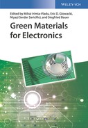
Dissolved and dissociated ions in an electrolyte are free to move via migration, diffusion, and/or convection [22]. Electric fields in the electrolyte act on the charged ions to provide migration and concentration gradients drive diffusion, while fluid movement is responsible for convection (Figure 3.1).
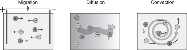
Figure 3.1 Ion transport mechanisms in electrolytes.
3.2.2.1 Migration and Diffusion
A difference in ion concentration ∆c between two points in an electrolyte results in ion transport through diffusion. Here, the random movement of molecules strives to level out the concentration difference, giving a net movement of ions from high to low concentration. The diffusion rate is dependent on the diffusion coefficient (D) for the molecule, expressed in square meter per second, and the concentration difference ∆c. The flux J (mol m−2 s−1) due to diffusion is governed by Flick’s first law:
A potential difference ∆ϕ between two points in an electrolyte, generated, for example, between two electrodes immersed in the solution, creates an electric field in the electrolyte. The field exerts a force on the ions in the electrolyte, and the resulting transport is termed migration. The direction of migration is dependent on the charge of the ion; cations move in the direction of the field while anions migrate in the opposite direction.
Owing to the charge carried by ions, transport through migration and diffusion is linked. A flux of ions due to migration perturbs the ion concentration, resulting in a concentration gradient and thus an opposing diffusion flux. Conversely, two oppositely charged ions with different diffusion coefficients diffusing in a concentration gradient induce an electric field in the electrolyte. This electric field opposes the diffusion movement of the faster diffusing species in order to maintain electroneutrality, and adds a migration component to the flux. The total flux, both accounting for migration and diffusion for an ion with charge z and concentration, c is described by the Nernst–Planck equation:
where F is Faraday’s constant, R is the gas constant, and T is the temperature. The first part in the Nernst–Planck equation accounts for flux due to diffusion, while the second accounts for migration.
3.2.2.2 Transport Number
As electrolytes contain more than one mobile species, the total flux of ions due to migration or diffusion is the sum of the fluxes for each species. The magnitude of the individual fluxes, and thus their proportion of the total flux, can vary, for example, due to differences in diffusion coefficient or concentration. The transport number describes the fraction of the flux from one specific ion species to the total flux, defined as unity, in the electrolyte. In electrolytes where the ions have similar diffusion coefficients and are at equal concentration, for example, KCl (![]() [23]), the cation and anion have roughly the same transport number of 0.5 (Figure 3.2). If, on the other hand, the diffusion coefficients differ, such as for HCl (
[23]), the cation and anion have roughly the same transport number of 0.5 (Figure 3.2). If, on the other hand, the diffusion coefficients differ, such as for HCl (![]() [23]), the transport number will be higher for the ion with higher diffusion coefficient (
[23]), the transport number will be higher for the ion with higher diffusion coefficient (![]() ) [24]. Similarly, a relative increase in concentration (compared to other mobile ions in the system) will also increase the transport number.
) [24]. Similarly, a relative increase in concentration (compared to other mobile ions in the system) will also increase the transport number.

Figure 3.2 Transport numbers. The ionic current in an electrolyte is composed of the total flux for all species present. The transport number describes the contribution from each species, and is higher for ions with higher diffusion coefficient ( ).
).
3.2.3 Ion-Exchange Membranes
Membranes can be used to separate two electrolytes while still allowing transport processes to occur between them, for example, ion transport across an ion-conducing membrane. Ion transport across membranes can also be selective, for example, toward either cations or anions, as in the case of ion-exchange membranes. Such a membrane typically contains fixed ionic charges, either cations or anions, often covalently hosted within a cross-linked polyelectrolyte matrix (Figure 3.3). Additionally, the membrane will contain mobile ions from the surrounding electrolytes. Through electrostatic interaction the fixed charges repel ions of the same charge (coions), while, to maintain electroneutrality, oppositely charged counterions are attracted. Thus, the counterion concentration is higher than the coion concentration inside the membrane. The fraction of counterion concentration ccou in relation to the total number of mobile ions (including coions cco) depends on the fixed charge concentration X of the membrane and the surrounding electrolyte concentration cs according to

Thus, for a highly charged membrane with X = 1 M and external electrolyte concentration cs of 0.1 M, approximately 99% of the mobile ions in the membrane are counterions [25]. This enhances the transport number for the counterion (and reduces the transport number for the coion), giving ion-exchange membranes selective transport for counterions. A cation-exchange membrane contains fixed anions and primarily mobile cations, and vice versa for an anion-exchange membrane; ion-exchange membranes can therefore be regarded as the ionic equivalent to p- and n-type (semi-)conductors. Typical selective ion-exchange membranes have fixed charge concentration of 1–3 M and a counterion transport number of >0.95 [26]. The counterion transport number is, however, reduced when the membrane is in contact with high-concentration electrolytes, as this increases the concentration of coions [27].

Figure 3.3 Ion-exchange membranes. Anion- and cation-exchange membranes are typically cross-linked polyelectrolytes, where cationic or anionic groups are covalently bound to a polymer chain. These fixed charges are compensated by mobile counterions, carrying opposite charge, while coions, ions with same charge, are repelled. Inside the membrane, the concentration of counterions is relatively higher than that of coions. Migration across ion-exchange membrane is therefore selective toward the counterion, that is, either anions for an anion-exchange membrane or cations for a cation-exchange membrane.
3.2.4 Bipolar Membranes
A bipolar membrane is a two-layered membrane with one side having cation-exchange properties and the other anion-exchange properties (Figure 3.4) [28]. The two sides, with either fixed anions or cations, will then contain either cations or anions as counterions, respectively, while the coions are repelled. Thus, the concentration profile for mobile cations and anions varies along the bipolar membrane. This structure is interesting, as it mimics the classical semiconductor pn-junction, and, as expected, bipolar membranes show nonlinear current versus voltage characteristics [29]. The mechanism for ion transport across a bipolar membrane is primarily divided into two regimes, the forward and the reverse bias regimes, depending on the voltage polarity applied to the membrane.
Figure 3.4 Bipolar membrane. The combination of a cation-exchange membrane and an anion-exchange membrane gives a changing ion concentration profile along the membrane, where one side is rich in mobile cations and the other in mobile anions. The current–voltage characteristics for bipolar membranes is nonlinear, showing two regimes: forward and reverse bias. Additionally, some bipolar membranes show accelerated water dissociation in the reverse bias regime.
3.2.4.1 Forward Bias Regime
A bipolar membrane is in forward bias when a positive voltage is applied at the cation-exchange side of the membrane. The electric field across the membrane is then directed so that the counterions of both sides of the membrane migrate toward the junction. The ions however cannot pass readily, as they are repelled by the fixed charges of the membrane on the other side of the junction. In contrast to holes and electrons, ions of different polarity do not recombine (except for acid/base with OH−/H+). Instead, ions initially accumulate at the junction. However, as the selectivity of an ion-exchange membrane is reduced with increased electrolyte concentration, the accumulation of ions leads to an increased coion transport across the junction. The mobile ions can therefore eventually pass the junction as compensated coions. In forward bias, the ion concentration along the bipolar membrane is high, resulting in high conductivity.
3.2.4.2 Reverse Bias Regime
Reversing the applied voltage, that is, applying a negative voltage at the cation-exchange side, brings the bipolar membrane into the reverse bias regime. Now, the direction of the electric field forces the counterions to migrate away from the junction. Additionally, only a small amount of coions can migrate toward the junction, as these are mostly repelled at the interfaces toward the electrolytes. Thus, the flow of counterions out of the junction is higher than the replenishing flow of coions, and the net result is a reduction in ion concentration inside the junction. The low ion concentration in the junction renders the reverse bias less conductive.
The low ion concentration at the interface in a reverse biased bipolar membrane implies a local high electric field across the interface. Together with catalytic groups, such as amines typically present in anion-exchange membranes, the electric field can increase the dissociation rate of water into ions (H+ and OH−) [30]. This effect is known as electric field-enhanced water dissociation, and is industrially important for separating salts into the corresponding acid and base components [31].
3.2.5 Electrodes
Pairs of electrodes are commonly used to generate ionic currents inside electrolytes.
If the electrodes are polarizable, the surface of the electrode will become electronically charged (negatively or positively) upon electrical biasing. This charge is compensated by a redistribution of ions in the electrolyte in proximity to the electrode, forming an electric double layer (EDL). Closest to the electrode surface, ions with opposite charge, with respect to the electrode, approach the electrode surface to form a so-called Helmholtz layer. Further away from the electrode the diffuse layer is formed, where there is a decaying abundance of oppositely charged ions. The spatial separation of positive and negative charges at the electrode/electrolyte interface resembles a capacitor. The polarizable electrodes can be charged or discharged similarly to an ordinary capacitance depending on the bias applied to the electrode, that is, the (capacitive) current between two polarizable electrodes for a given applied bias decays with time.
In addition, electrochemical reactions can occur at the electrode surface, giving rise to a faradic (charge-transfer) current. Electrolysis of water, where water molecules are split into H2 and O2 at the cathode and anode respectively and H+ and/or OH− migrate between the electrodes, is an example of such a reaction. For reduction and oxidation to occur at the electrodes, the applied bias must be above the decomposition potential of the electrochemical species, for example, 1.23 V for water. The faradic current can be maintained as long as electrochemically active species are present at the electrode, and the current is thus limited by diffusion of the active species from the bulk of the electrolyte.
Compared to solid metal electrodes, conjugated polymers can be charged not only along the surface but also throughout the bulk of the electrode. They thus offer a large effective electrode area and an increased electrode capacitance [32]. When such an electrode is electrically biased, electrons are inserted into or removed from the polymer backbone, that is, the entire polymer bulk, increasing or decreasing the charge, or doping level, of the conjugated polymer. The change in doping level is compensated by oppositely charged ions migrating in or out from the polymer matrix. In this way, conjugated polymer electrodes can be used as high-capacity electron-to-ion converters, without production of soluble redox products, pH changes, or gases [33].
3.3 Organic Electronic Ion Pump
Devices for in vivo drug delivery are commonly based on either diffusion (controlled by a valve-mechanism) or microfluidic flow. Diffusion-based devices typically suffer from a lack of control, for example, as the rate of delivery decays with time and swift on/off responses are typically hard to realize. Microfluidic flow can offer precise control of the delivery, but at the expense of complicated “plumbing” and potential disturbance of the biological processes due to the physical liquid flow. An alternative approach, at least for molecules that are charged or can become charged (through protonation/deprotonation), is electrophoresis. In this technique, the rate of delivery can be tightly controlled electronically, and liquid flow is extensively minimized. The organic electronic ion pump (OEIP) is a microfabricated drug delivery device based on electrophoresis, and has been specifically designed for biomolecule interfacing with cells and tissues in vivo and in vitro.
The OEIP is designed according to the following principles (Figure 3.5):
- Faradic currents between the two included electrodes immersed in their electrolytes give rise to an electric field. Ions in the electrolytes will migrate in the direction of the field, cations toward the cathode and anions toward the anode.
- The electrolytes are separated by an ion-conductive membrane. If the membrane is cation or anion selective, the transport of ions across it, for a given bias, will primarily be unidirectional and only composed of cations or anions.
- The rate of ion transport (mol s−1) across the membrane is in direct correlation to the faradic current provided through the electrodes, giving temporal control of the ion delivery (J = i × F).
- The membrane can have arbitrary shape, and, for example, have a very thin end on one side. This gives spatial resolution to the delivery.

Figure 3.5 The organic electronic ion pump, with two electrodes immersed in electrolytes (designated as source and target), separated by an ion-exchange membrane (here a cation-exchange membrane). A voltage applied between the electrodes drives a selective transport of cations from the source to the target side through the channel.
The very first version of the OEIP was produced on flat plastic sheets coated with poly(3,4-ethylenedioxythiophene):polystyrene sulfonate (PEDOT:PSS). The electrodes and the cation-selective channel were formed through photolithography and dry-etching of the PEDOT:PSS layer. A tapering channel, with the narrower end pointing toward the outlet, gives high spatial resolution without an undesired high resistance. Through chemical overoxidation, the PEDOT:PSS in the channel is rendered electronically isolating while retaining the ionic (cation) conductivity, thus preventing electric short-circuit or electrochemical oxidation fronts in the channel. Lately, the overoxidized PEDOT:PSS material has been replaced by a purer poly(styrenesulfonate) copolymer [34]. An encapsulation layer, using the epoxy-based hydrophobic photoresist SU8, is used to define the inlet and outlet of the channel as well as the storage regions for the electrolytes.
Any type of electrodes can be used, but it is advantageous to have electrodes that can provide large amounts of charge, at low potential loss, without formation of gas, toxic species, or pH changes. Electrodes made of conjugated polymer materials, such as PEDOT:PSS, are therefore attractive, as they have been shown to provide stable faradic currents without significant side reactions [33].
Before using an OEIP, the channel material needs to be hydrated in order to become sufficiently ion conductive. This is typically done by incubation in de-ionized water over extended periods (several hours). Electrolytes are then applied to the source and target reservoir regions. The source electrolyte should contain the ion to be transported, carrying the correct charge (positive or negative depending on channel selectivity). Additionally, it is preferred if the ion to be transported is in higher concentration than any other similarly charged ions in the electrolyte, as this reduces the transport of unintended ions. Extreme pH is therefore undesirable, as this can lead to high transport of H+ or OH−. The target electrolyte can be comprised, depending on the application of a simple salt electrolyte, more complex buffers, a cell culture hosted in a medium, or even a tissue or an organ.
Electronically, an OEIP can be regarded as a resistor. The low (ionic) conductivity inside the channel combined with the preferred long and narrow channel geometry leads to a high resistance and typically limits the current through the device. The off-current, when no voltage is applied, is primarily due to diffusion of molecules between the source and target. The on–off ratio for metal ion and biomolecule delivery is typically above 100 [35, 36].
3.3.1 Applications
OEIPs have been used in a number of studies as a drug delivery platform for stimulation of neuronal cells both in vitro and in vivo. In the first report [35], human cortical neurons (HCN-2) loaded with a Ca2+-sensitive fluorescent probe were cultured at the outlet of the OEIP and were then stimulated by a constant flux of K+ from a source electrolyte. The increase in K+ concentration caused opening of cellular Ca2+ channels, and cells close to the OEIP outlet showed subsequent increase in the intercellular Ca2+.
A refined design of the OEIP was later presented [36], enabling faster delivery response due to the inclusion of a preload configuration, as well as an increased spatial resolution of the delivery thanks to reduction of the outlet width down to 10 µm. The improvements allowed for triggering of Ca2+ responses in cultured SH-SY5Y cells close to the outlet through stimulation with the neurotransmitter acetylcholine, with a response time below 200 ms. Owing to the rapid diffusion of the delivered species away from the outlet, pulsing of the delivery and also varying the pulse length and amplitude allowed for selective stimulation of only the cells located closest to the outlet.
Further, the OEIP has been used for in vitro modulation of neuronal activity in mouse brain slices [34]. By delivery of K+ to neurons in the hippocampus, hyperexcitability, an abnormal electrophysiological neuronal activity associated with epilepsy, could be induced (Figure 3.6a). Conversely, by delivering the inhibitory neurotransmitter γ-aminobutyric acid (GABA), epileptiform activity could be suppressed in the hippocampus after hyperexcitability had been induced by regular electrophysiological methods. Even more recently, the device was further augmented to incorporate a PEDOT:PSS-based electrophysiological sensing electrode at the OEIP outlet [38]. In this way, a 20 µm × 20 µm “bioelectronic pixel” was demonstrated that could both deliver GABA (as the outlet of the OEIP) and sense the local electrophysiological state (as a PEDOT:PSS electrode). Experiments showed that the bioelectronic pixel could perform just as well as the earlier system, which relied on “standard” macroscopic recording electrodes. Thus, the OEIP is an effective tool in regulating neuronal signaling activity in the complex biological settings of real tissues, and is furthermore able to be integrated directly with electrophysiological sensing for feedback-enabled interventions.

Figure 3.6 In vitro and in vivo applications of the OEIP. (a) GABA delivered through OEIP outlets placed in close proximity to the CA1 region of a mouse hippocampal slice suppressed epileptiform activity in that area, while the activity in the more distant CA3 region was unaffected.
Williamson et al. 2015 [34]. Reproduced with permission of John Wiley and Sons.) (b) An OEIP with four parallel outlets, spaced to match the positions of four dorsal roots (in rats) where the pain signal enters the dorsal spinal cord. Once implanted onto the spinal cord, local delivery of GABA through the device reduced the pain response in the rats.
Jonsson et al. 2015 [37]. Reproduced with permission of AAAS.) This work is licensed under CC BY-NC. (c) Examples of biomolecules (neurotransmitters) that have successfully been transported with the OEIP.
It is also possible to couple the chemical delivery from an OEIP together with chemical sensing, for example, of a neurotransmitter. Such systems have been demonstrated for cultured neuroblastoma SH-SY5Y cells, using electrochemical sensors for glutamate or acetylcholine and the OEIP for delivery of acetylcholine [39]. Here, the sensing of glutamate and delivery of acetylcholine mimics the signaling pathway at the neuromuscular junctions, while acetylcholine sensing and delivery can be used as a self-regulating loop to maintain normal acetylcholine levels. By defining thresholds in the sensing signal for activation of the neurotransmitter delivery, neuron-like behavior is obtained, that is, a signal is only transmitted if the stimuli reach a threshold concentration. Thus, the combined biosensor-OEIP system has been dubbed as an organic electronic biomimetic neuron.
OEIPs have also been adapted for implantation and for in vivo use. For this purpose, the usual planar design was converted into a tubular, narrow, and fully encapsulated device in order to be as nonintrusive and biocompatible as possible. The first device consisted of two parallel electrodes, electrolyte compartments, and channels, both with outlets at the tip of the device [40]. One side of the device served as the source and the other as the counter electrode/electrolyte, while the delivery target was the electrolyte the tip was immersed in. The syringe-shaped OEIP was implanted in close proximity to the round window membrane of the cochlear in a guinea pig, with the aim of specific chemical stimulation and also regulation of the auditory system. Through local delivery of glutamate the hearing sensitivity was reduced, as the inner hair cells were affected by the excessive glutamate concentration. Meanwhile, the outer hair cells, not sensitive to glutamate, were not affected, and no effect was observed when delivering protons. This implanted OEIP thus successfully stimulated the glutamate-responsive inner hair cells (and destroyed them) through the active delivery of glutamate, without damaging or affecting other, non-targeted parts of the sensitive cochlea system.
The adaption of the OEIP to the specific biological target can also be more sophisticated. For example, to restore inhibitory pain control in a hypersensitized rat model, the channel of an OEIP was specifically designed to have one outlet aligned at each of the four dorsal roots where the pain signals enter the spinal cord (Figure 3.6b) [37]. By delivery of GABA, which inhibits the pain signal, to these specific sites the pain response threshold was significantly increased in a hypersensitive rat model. Compared to other methods for chronic pain pharmacotherapy, such as systematic administration of drugs, this implantable OEIP only affects its immediate surroundings of the nervous system and can thus potentially suppress side effects.
3.3.2 Limitations
The ability and speed of migration for a specific ion through the ion pump channel is to a large extent dependent on the size of the ion. Some examples of biomolecule ions that have been delivered with OEIPs are shown in Figure 3.6c. Large ions, such as biomacromolecules, typically have lower diffusion coefficient, resulting in a higher ionic resistance and thus require a relatively higher driving voltage. This lower diffusion coefficient also means that small coions, with higher diffusion coefficient, will be relatively easier to transport in the reverse direction, which will reduce the delivery efficiency. Additionally, the polymer in the membrane material of the channel can act as a size-exclusion mesh that prevents large molecules, such as peptides, to pass. Thus, to date, the ion pump works best for the delivery of smaller ions, such as metal ions and biomolecules with molecular weight less than ~200 g mol−1, while larger molecules show low delivery speed and efficiency.
3.4 Ion Diodes, Transistors, and Circuits
Apart from just transporting ions through electrophoresis, as in OEIP devices, more complex operations involving ions are also of interest, such as ionic signal rectification or amplification. Such capabilities could enable ion-based computing and delivery systems to generate complex biomolecule signal patterns. For such operations, devices with nonlinear characteristics are needed, that is, diodes and transistors that operate on ionic signals and flows. For logic functions, schemes devised around motion of ions are inherently slow compared to their electronic counterparts, primarily owing to the several orders of magnitude lower mobility for ions. The advantage of iontronic-based logic circuits in bioelectronic applications is instead related to the opportunity to achieve advanced and complex patterns of chemical information; as opposed to the charge-only nature of an electron (or hole), an ion can have a wide range of different molecular structures, configurations, reactivity, and so on, and can thus carry information specific to biological systems and their functions. For example, an ionic transistor modulating a flow of glutamate ions will have a distinctly different effect than if the flow is represented by GABA ions, as the first molecule is an excitatory neurotransmitter while the latter is inhibitory.
3.4.1 Ion-Conducting Diodes
Diodes are nonlinear two-terminal electrical components that have significantly lower resistance in one direction. In other words, the current through the diode is dependent on the voltage polarity. Various types of ion-conducting diodes have been presented, primarily based on either nanofluidic channels or ion-exchange membranes (bipolar membranes) (Figure 3.7). Nanofluidic ion diodes typically utilize charged sidewalls along a nanometer-sized channel. The channel is divided into two sides, with either negatively or positively charged sidewalls. EDLs form along the charged sidewalls, which accumulate the counterion while repelling the coions. Owing to the small dimensions, the EDL can affect the entire channel. The ion distribution along nanofluidic diodes thus resembles a bipolar membrane. However, the EDL thickness is highly dependent on the electrolyte concentration, and decreases from 3.1 nm at 10 mM to 1.0 and 0.3 nm at 100 mM and 1 M, respectively [41]. Owing to the difficulty in fabricating single-nanometer channels, nanofluidic ion diodes perform best at low electrolyte concentrations (typically <10 mM) but poorly at higher concentrations, and thus are not promising for biological applications at physiological conditions.

Figure 3.7 Ion diodes based on surface-charged nanofluidic channels or bipolar membranes.
Ion-exchange membranes, with fixed charges distributed throughout their bulk, can typically maintain good selectivity even at relative high surrounding ion concentration. Thus, for biological applications, diodes based on bipolar membranes are preferable. These can be manufactured by photolithography, similar to OEIPs, by connecting two channels comprising a cation- and an anion-selective membrane, forming the anode and cathode of a diode (Figure 3.8a) [44]. Micrometer-scaled bipolar membrane structures can also be obtained through photo-crosslinking polyelectrolyte gels in microfluidic systems [45]. Both these microfabricated ion diodes will exhibit current–voltage characteristics based on the forward and reverse regime of bipolar membranes.
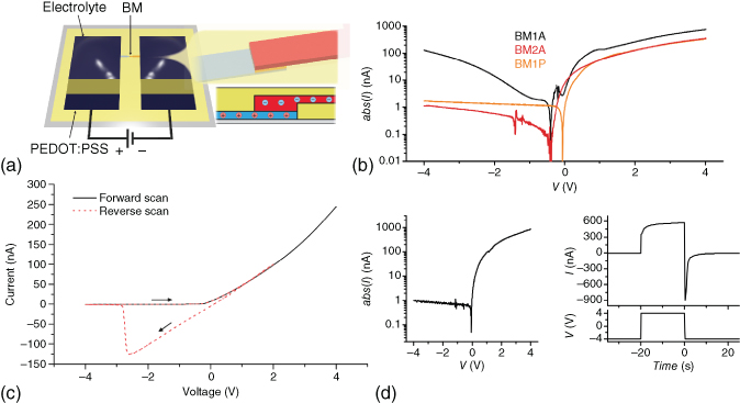
Figure 3.8 Structure and characteristics of ion bipolar membrane diodes. (a) Ion bipolar membrane diodes can be constructed by layering photolithographically patterned cation-exchange membrane (blue) and anion-exchange membrane (red), forming a bipolar membrane. The diode is ionically connected to PEDOT:PSS electrodes through two electrolytes.
(Gabrielsson et al. 2014 [42]. Reproduced with permission of John Wiley and Sons.) (b) Ionic current rectification between forward and reverse bias for three types of bipolar membrane diodes. Water dissociation is observed in BM1A while avoided in BM2A and BM1P through the use of neutral electrolyte junction and non-amine-based anion-exchange membrane, respectively.
Gabrielsson and Berggren 2013 [43]. Reproduced with permission of AIP Publishing.) (c) Hysteresis is often observed when changing from the forward bias regime to reverse bias, due to accumulation of ions during forward bias operation.)
(Gabrielsson et al. 2012 [44]. Reproduced with permission of Royal Society of Chemistry.) (d) The performance of ion bipolar membrane diodes can be improved by minimizing the junction size, here down to 10 µm, as less charge then needs to be injected/extracted.
(Gabrielsson et al. 2013 [43]. Reproduced with permission of AIP Publishing.)
In the forward bias regime, a positive voltage is applied to the anode terminal versus the cathode potential. Mobile ions can then migrate inside the bipolar membrane with high conductivity without formation of regions of low ion concentrations. It has been observed that counterions eventually cross the interface and become coions during forward bias [46]. The current through the bipolar membrane is thus composed of both counterion and coion migration. The main voltage drop occurs across the two ion-exchange membranes owing to their bulk resistivity, and the current increases approximately linearly with applied voltage.
When a negative voltage is applied at the anode, versus the cathode potential, the reverse bias regime is obtained. As the direction of the electric field is reversed, the bipolar membrane interface becomes depleted of ions. As ionic conductivity is dependent on the concentration of ions, the interface region exhibits low conductivity. The low conductivity of the interface renders the bipolar membrane less conductive as compared to the forward bias, thus giving the current–voltage asymmetry that enables bipolar membrane diodes to rectify ion currents (Figure 3.8b). The main potential drop for the reverse bias operation occurs across the ion-depleted interface.
In addition to the ideal forward and reverse bias regimes, an additional, nonideal diode property can be observed in some ion bipolar membrane diodes, where the reverse bias conductivity rapidly increases at higher negative voltages than ~−1 V. This is due to electric field-enhanced water dissociation, where H2O is split into H+ and OH− (BM1A in Figure 3.8b). The generated H+ and OH− are separated by the electric field and migrate away from the interface. Corresponding acidic and basic pH changes can be detected at the anode and cathode electrolyte, respectively. As the bipolar membrane interface is no longer depleted of ions, and as H+ and OH− both have high mobility, the conductivity through the ion bipolar membrane diode is significantly higher than in the true reverse bias regime. This can diminish the rectification ratio to reach below 10 at voltages beyond ±1 V [43, 44], and thus reduces the usefulness of such devices as diodes. Two strategies have been employed to avoid the water dissociation effect. First, a neutral electrolyte can be inserted into the interface of the bipolar membrane [44, 47]. This redistributes the potential drop across a longer distance, reducing the local electric field strength. Secondly, the typical amine-based anion-selective membrane can be replaced by a less catalytic phosphonium polyelectrolyte [43]. Using such approaches, rectification ratios of around 800, at ±4 V, can be obtained [43].
Hysteresis is often observed when switching an ion bipolar membrane diode from forward to reverse bias [44, 46]. This is primarily due to the accumulation of ions in the bipolar membrane interface during forward bias. In contrast to electrons and holes in semiconductor diodes, cations and anions do not recombine and annihilate (except in water formation by H+ and OH−), and significant amounts of ions can therefore be stored at the interface. The accumulated ions need to be removed to reach the reverse bias condition of ion depletion in the interface, and thus a delayed rectification is observed when going from forward to reverse bias operation (Figure 3.8c).
If the interface volume is small, for example, the cation- and anion-exchange membranes are in direct contact, the concentrations of accumulated ions can approach the concentration of fixed charges at either side of the bipolar membrane. This lowers the charge selectivity of the ion-exchange membranes, and thus allows ions in the interface to continue migrating along the electric field as coions in the previously prohibited side of the bipolar membrane. Conversely, if the interface volume is large, as in the case of ion bipolar membrane diodes with an intermediate neutral layer at the interface, relatively much larger amounts of ions can be accumulated before coion transport occurs. As a consequence, the hysteresis is higher for the latter type of ion bipolar membrane diodes as compared to the former case. Although generally regarded as an unwanted feature, the hysteresis in ion diodes has been suggested to be useful for iontronic memory devices [48].
The time required to switch an ion bipolar membrane diode from the nonconductive reverse bias to the conductive forward bias state, and vice versa, is highly dependent on the dimensions of the bipolar membrane interface, as this dictates the amount of ions that need to be injected or extracted from the junction. Improved switching times, from >10 s down to 4 s in both directions, have been demonstrated for ion bipolar membrane diodes when the interface lengths were reduced from 50 to 10 µm [43] (Figure 3.8d).
3.4.2 Transistors for Modulating Ion Flows
Transistors are three-terminal devices where the bias applied at one terminal modulates the current between the two other ones. In a bipolar junction transistor, the modulating terminal is called base and has opposite polarity compared to the emitter and collector terminals between which the current is modulated. The structure resembles two connected pn-junctions forming a T-junction (Figure 3.9d). Thus, similar to ion diodes, ion bipolar junction transistors (IBJTs) can be made by connecting two bipolar membranes; for example, one anion-exchange membrane, serving as base, forms a T-junction with two cation-exchange emitter and collector membranes. The two junctions are named emitter–base (EB) and collector–base (CB), and each of them exhibits diode behavior. Depending on the selectivity of the emitter and collector (either for cations or for anions) the IBJT is either a pnp- or an npn-transistor. In a pnp-IBJT, a cation current between emitter and collector (collector current, IC) is modulated by injection and extraction of anions through the base (base current, IB) [47], and in the complementary npn-IBJT the polarity is reversed [49].
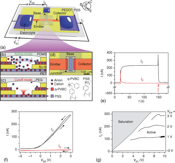
Figure 3.9 npn-IBJT device geometry, modes of operation, and characteristics. (a) The anion-selective emitter and collector are connected to a cation-selective base. The base and collector are biased versus the emitter with VEB and VEC, respectively, through electrolyte-covered PEDOT:PSS electrodes. (b) In the active mode VEB > 0 V and cations are injected into the junction, enabling anions to cross between emitter and collector. (c) In the cutoff mode ions are removed from the junction through the base and collector. (d) A neutral PEG-based electrolyte separates the emitter, collector, and base. The emitter–collector distance is 100 µm. (e) Switching characteristics between cutoff (VEB = −3 V) and active mode (VEB = +3 V). Momentarily after the switch in VEB, a spike in IB injects/extracts cations to/from the junction. The 90% rise and 10% fall times are 9 and 3 s, respectively. (f) Transfer curve (VEB = 10 V). IC is low for VEB < 0 V and increases linearly for VEB > 0 V, while IB is low through the scan. (g) Output characteristics. In the voltage range studied, IC increases with VEB but is almost constant with respect to VEC, that is, IC is saturated in the active mode.
(Tybrandt et al. 2011 [49]. Reproduced with permission of American Chemical Society.)
To operate a single IBJT, the emitter, base, and collector terminals are connected to individual electrolytes and electrodes (Figure 3.9a). A voltage VEC is applied between the emitter and collector electrodes in order to drive the migration of the main charge carriers from the emitter toward the collector. Another voltage (VEB) is applied between the emitter and the base electrodes to enable modulation of IC.
Depending on VEC and VEB, the IBJT is operated in one of four modes: active, cutoff, reverse active, or saturation. The mechanisms for ion transport in these modes are similar between the pnp- and the npn-IBJTs, differing primarily only in the polarity of the ions involved and bias potentials. Thus, the npn-configuration will be discussed in detail. Further, a configuration with symmetrical emitter–collector is assumed.
In the active mode, both VEC and VEB are positive, and VEB < VEC/2. As VEB is positive, the EB junction is forward biased, and both anions and cations are injected into the junction through the emitter and base terminals, respectively, giving a positive IB (Figure 3.9b). The increase in ion concentration leads to an increased conductivity of the junction, and anions can move across the junction. The CB junction is, on the other hand, reversely biased and tries to deplete the junction. The anions extracted through the collector give rise to a high IC, which defines the on-current (Figure 3.9e). The potential drop across the emitter due to the on-current elevates the potential at the junction and limits the IB as the potential across the EB junction is reduced. As IB is low in steady state, IC depends primarily on the collector resistance and VEB, that is, IC increases with VEB (Figure 3.9f). In the active mode, the ion concentration inside the junction linearly decreases from the emitter to the collector and an ion-depleted region appears at the collector, across which anions diffuse. The ion-depleted region increases in length with increased VEC, and IC is thus almost constant versus VEC (Figure 3.9g).
The saturation mode is established if the VEB is increased above VEC/2, so that CB also becomes forward biased. This leads to continuous accumulation of ions inside the junction and high currents (IC and IB). For this reason, the saturation mode is preferably avoided in IBJTs, as high ion concentration can lead to extensive swelling of the junction, which then can deteriorate the characteristics of the junction.
By reversing the VEB to negative potential, both EB and CB are in reverse bias, putting the IBJT in the cutoff mode. Cations will then be extracted through the negative biased base (Figure 3.9c). To maintain charge neutrality in the junction the concentration of anions also decreases, primarily by extraction of anions through the higher biased collector. As the junction is depleted of ions, the conductivity becomes limited, resulting in a low IC (off-current).
If instead a negative VEB and VEC are applied, the forward/reverse bias state of EB and CB is changed (as compared to the active mode), leading to the reverse active mode. For a symmetric IBJT this mode is equal to the active mode.
The time for switching an IBJT from cutoff to active mode, and vice versa, depends to a large extent on the dimensions of the actual junction, that is, how large a volume needs to be injected with or depleted of ions. For high-speed operation, it is therefore advantageous to design the IBJT with minimal distance between the emitter and the collector [50]. IBJTs with 2 µm emitter–collector distance have shown switching speeds of around 2 s [51]. The ratio between the ICs in the active and cutoff modes (the on–off ratio) is typically around 100, while the gain (ratio between IC and IB in active mode) is typically around 10 [47].
3.4.3 Applications
3.4.3.1 Modulating Neurotransmitter Flow
The emitter and collector of an IBJT are similar in structure to the channel of an OEIP. IBTJs can therefore be used for electrophoretic transport of ions from a source electrolyte, through the collector, junction, and emitter, to a target electrolyte. The advantage over an OEIP is that the transport can be controlled via the base terminal, thus separating the voltage used to drive the electrophoresis from the on/off signal. For example, a pnp-IBJT has been used to stimulate SH-SY5Y cells by delivery of acetylcholine, where the delivery was triggered and modulated by pulsing the EB voltage (VEB) while holding the emitter–collector voltage (VEC) constant (Figure 3.10) [47]. One could further connect the base input to another ionic or chemical circuit, to realize complex autoregulated delivery, for instance, feedback-regulated delivery of a neurotransmitter.

Figure 3.10 Modulation of acetylcholine neuronal signaling with a pnp-IBJT. (a) SH-SY5Y cells were cultured at the collector outlet of the IBJT, while an electrolyte containing acetylcholine was loaded at the emitter. VEC is held constant at +10 V, while acetylcholine delivery is actuated through switching VEB between −1 V (off) and +4 V (on). (b) Acetylcholine receptors respond to the delivered acetylcholine by opening membrane-bound ion channels resulting in an influx of Ca2+, which is detected with a Ca2+-sensitive fluorescent probe.
(Tybrandt et al. 2010 [47]. Reproduced with permission of PNAS.)
3.4.3.2 Diode Logics
The rectification property of ion bipolar membrane diodes enables them to be used in simple diode-based logic circuits for ionic computing. For example, Han et al. have presented integrated AND, OR, and NAND-gates manufactured in microfluidic systems filled with gelled polyelectrolytes [45]. These gates function as ordinary diode-resistor logic gates. In the AND-gate (Figure 3.11), the cathode side of two ion diodes is connected to individual input terminals, while the anode side is connected through a resistor to a positive bias supply. The logic output signal is measured as a voltage drop across the resistor. When one or both of the diodes are biased at 0 V (i.e., forward biased), the voltage drop over the resistor due to the forward bias current pulls the output voltage down toward 0 V. If, on the other hand, both diodes are biased above the positive bias supply voltage, both pathways are reverse biased and the output remains at the positive bias voltage. Additionally, the light emission from a fluorescent dye, fluorescein, acting as an anion in the bipolar membrane, enabled a visual readout of the logic state.

Figure 3.11 Ion diode-based AND-gate. (a) The gate contains two bipolar membranes, formed by gels of Poly(diallyldimethylammonium chloride) (pDADMAC) and poly(2-acrylamido-2-methyl-1-propanesulfonic acid) (pAMPSA). (b) Inputs (V1 and V2) are connected to the cathode side of the diodes, while the output is measured across the resistance of a microfluidic channel. (c) Truth table. The output is only high for the input combination V1 = V2 = 1, that is, the gate shows AND-functionality. (d) A fluorescent dye in the bipolar membranes gives a visual readout of the diode state (forward/reverse biased).
(Han et al. 2009 [45]. Reproduced with permission of John Wiley and Sons.)
3.4.3.3 Transistor Logics
Diodes can only be used to realize a small range of logic gates, and they offer no signal gain. In addition, the hysteresis and the bidirectional transport observed in ion bipolar membrane diodes can be disadvantageous, especially in drug delivery applications. Current amplifying transistors are thus often more suitable for designing logics gates. IBJTs have therefore been employed to construct inverters and NAND-gates, in both npn and complementary (using both npn and pnp) IBJT circuits [52]. These gates, including resistors, conductors, transistors, and electrodes, were integrated on single chips (Figure 3.12). Even though the characteristics for the IBJTs might not be ideal, the obtained response from the gates is feasible and shows the expected behavior. For inverters the complementary designs show higher gain and lower power consumption than the single npn-type. One severe limitation is, however, the low switching speed, typically reaching ~100 s. This could however potentially be improved by using smaller, and thus faster, transistors [51].
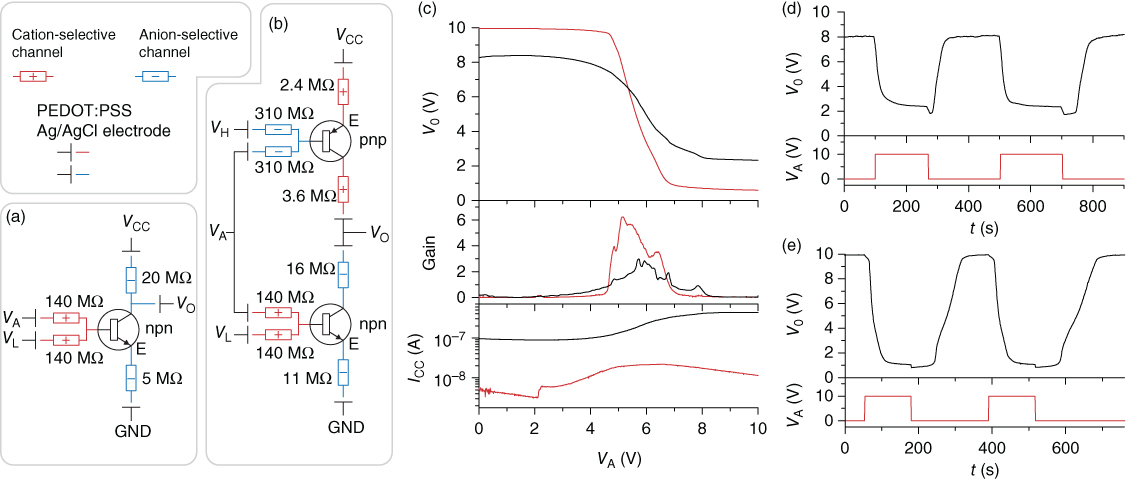
Figure 3.12 Ionic inverter gates based on IBJTs. (a) npn-Type and (b) complementary type inverter circuits. (c) The input signal VA is inverted to the output signal VO, that is, high VA gives low VO and vice versa. The complementary type inverter (red) offers better swing and gain and lower supply current (ICC) than the npn-type inverter (black). (d) Pulse responses for the npn-type and (e) complementary type inverter. The response is slow owing to the slow performance of the IBJTs.
(Tybrandt et al. 2012 [52]. Reproduced with permission of Nature Publishing Group.)
The reported ion transistors logic gates, especially the complementary NAND-gate including four transistors [52], show the feasibility of integrating several iontronic components into functional circuits. One of the more interesting applications for this type of ion-conducting logic gates is the delivery of chemicals and drugs in 2D or 3D grids, where the points in the array contain an ionic logic gate and could be individually addressed in an X–Y–Z manner. Such advanced delivery device would be useful to produce and control complex chemical patterns for the stimulation of target tissue functions.
3.4.3.4 Full-Wave Rectifier
Even though the use of conjugated polymers as electrode material elevates the useful safe capacity range compared to metal electrodes, such electrodes can still be electrochemically “consumed” and may produce undesired side reactions, such as pH changes, when operated for extended periods [33]. This can be a problem for iontronic devices aimed at delivering large amounts of charged molecules over extended times, especially if the dimensions of the electrode are restrained, as, for example, in systems designed for use in vivo.
An elegant solution to this problem is to apply a continuously alternating input voltage to the electrodes, and then rectifying the resulting ion current with the use of an ionic full-wave rectifier [42]. A commonly used circuit for full-wave rectification of alternating currents is the four-diode bridge circuit, where regardless of the polarity of the input voltage, the polarity at the output is always the same. An equivalent ionic circuit can be produced by replacing the diodes with ion bipolar membrane diodes (Figure 3.13a). When an input voltage is applied, one input electrode is oxidized and the other is reduced, and switching the input polarity reverses the oxidation/reduction. Meanwhile, ion diode circuits located between the electrodes ensures that the voltage between the output reservoirs is always positive (Figure 3.13c,d).
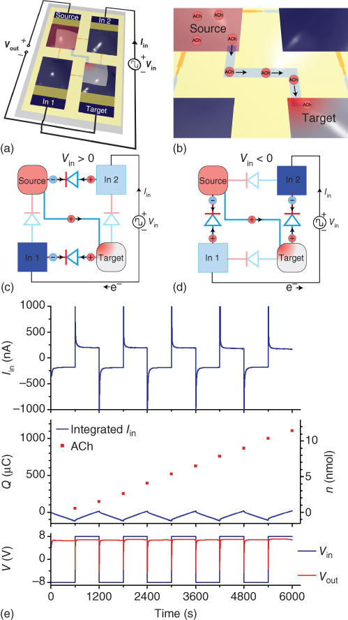
Figure 3.13 Ionic rectification of an input AC signal into a DC acetylcholine output signal. (a) The rectifying ionic bridge is biased with Vin at the two input PEDOT:PSS electrodes. (b) The output terminals are connected by a cation-selective channel. Acetylcholine is loaded at the source side (positively biased) and delivered to the target side (negatively biased). (c) and (d) Regardless of the input bias polarity, the four ion diodes direct the current in the same direction between the output terminals (source and target electrolytes). (e) The input current Iin follows Vin, switching between positive and negative. The voltage over the output, Vout, is however predominantly positive. The accumulated delivery of acetylcholine into the target suggests that the delivery rate is independent of Vin polarity.
(Gabrielsson et al. 2014 [42]. Reproduced with permission of John Wiley and Sons.)
By placing a channel of an ion-exchange membrane between the output reservoirs, the circuit can be used as an OEIP, where the transport of ions between the reservoirs is rectified (Figure 3.13b). This circuit was used to demonstrate electrode-independent delivery of acetylcholine (Figure 3.13e). An alternating input signal of ±8 V, with a 20 min period, was applied to the input electrodes, resulting in a steady-state input current of around ±200 nA. The ion bipolar membrane diode circuit rectified this input, at steady state, to +6.8 V over the output. Acetylcholine was loaded into the positive biased output reservoir, while the negative biased output reservoir, containing NaCl, was sampled at every switch in input polarity. The acetylcholine content of the sampled solutions was analyzed, and showed an average delivery of 1.1 nmol of acetylcholine per switch cycle, equivalent to an average delivery rate of 1.83 pmol s−1, and a corresponding total delivery of 1.1 mC of charge over five periods. Owing to the alternating oxidation/reduction of the electrodes, only approximately 120 μC of electrode capacity was used. Thus, the circuit can decouple the generation of ionic currents through electrode reactions from the charge-compensating capacity of the electrode.
A potential future use for this ionic full-wave rectifier is to extend the electrode lifetime in devices intended for long-term in vivo applications, for example, pain relief achieved through iontronic drug delivery [37]. The device footprint of such device would preferably be as small as possible, while large output capacity is still required. With the rectifier, the electrode area can be minimized, and the limitation is instead the source compartment of the biomolecules (which at saturated concentration could likely hold sufficient therapeutic substance for long-term operation).
3.5 Conclusions
Conventional electronic devices have evolved from the first transistors introduced in the 1940s to integrated circuits and today’s modern (CMOS) computer chips fabricated on silicon wafers using photolithography. For ion-conductive circuits for human–machine interfacing, we now have a basic set of individual components: conductors, resistors, diodes, and transistors. Additionally, with tools and processes borrowed from semiconductor fabrication, simple integrated ionic circuits are also realizable. Future improvements of such components and circuits will hopefully lead to a Moore’s law-like development of ionic human–machine interfacing technology. Of special interest is the possibility for amplification and addressability of chemical signals offered by circuits of ion transistors, as this has the potential to enable precise and local modulation of biological processes through generation of complex, spatially and temporally fluctuating biomolecule patterns in a 3D environment. Compared to, for example, the successful pacemaker using a single electrode for electronic stimulation, such ionic circuits would broaden the spectrum of biological signals the human–machine interface can leverage. Further, as the involved materials are polymer-based, and the technology lends itself to integration with organic electronics on flexible substrates, human–machine devices using ionic devices can be made biocompatible.
References
- 1 Polikov, V.S. , Tresco, P.A. , and Reichert, W.M. (2005) Response of brain tissue to chronically implanted neural electrodes. J. Neurosci. Methods , 148 (1), 1–18.
- 2 Anderson, J.M. , Rodriguez, A. , and Chang, D.T. (2008) Foreign body reaction to biomaterials. Semin. Immunol. , 20 (2), 86–100.
- 3 Azemi, E. , Lagenaur, C.F. , and Cui, X.T. (2011) The surface immobilization of the neural adhesion molecule L1 on neural probes and its effect on neuronal density and gliosis at the probe/tissue interface. Biomaterials , 32 (3), 681–692.
- 4 Cui, X. , Lee, V.A. , Raphael, Y. , Wiler, J.A. , Hetke, J.F. , Anderson, D.J. et al. (2001) Surface modification of neural recording electrodes with conducting polymer/biomolecule blends. J. Biomed. Mater. Res. , 56 (2), 261–272.
- 5 Strumwasser, F. (1958) Long-term recording from single neurons in brain of unrestrained mammals. Science , 127 (3296), 469–470.
- 6 Fromherz, P. , Offenhäusser, A. , Vetter, T. , and Weis, J. (1991) A neuron-silicon junction: a retzius cell of the leech on an insulated-gate field-effect transistor. Science , 252 (5010), 1290–1293.
- 7 Maynard, E.M. , Nordhausen, C.T. , and Normann, R.A. (1997) The utah intracortical electrode array: a recording structure for potential brain-computer interfaces. Electroencephalogr. Clin. Neurophysiol. , 102 (3), 228–239.
- 8 Connors, B.W. (2005) Synaptic transmission in the nervous system, in Medical Physiology (eds W.F. Boron and E.L. Boulpaep ), Elsevier Saunders, Philadelphia, PA.
- 9 Simon, D.T. , Gabrielsson, E.O. , Tybrandt, K. , and Berggren, M. (2016) Organic bioelectronics: bridging the signaling gap between biology and technology. Chem. Rev. , 116 (21), 13009–13041. doi: 10.1021/acs.chemrev.6b00146
- 10 Friend, R.H. , Gymer, R.W. , Holmes, A.B. , Burroughes, J.H. , Marks, R.N. , Taliani, C. et al. (1999) Electroluminescence in conjugated polymers. Nature , 397 (6715), 121–128.
- 11 Dimitrakopoulos, C.D. and Malenfant, P.R.L. (2002) Organic thin film transistors for large area electronics. Adv. Mater. , 14 (2), 99–117.
- 12 Günes, S. , Neugebauer, H. , and Sariciftci, N.S. (2007) Conjugated polymer-based organic solar cells. Chem. Rev. , 107 (4), 1324–1338.
- 13 Khodagholy, D. , Doublet, T. , Gurfinkel, M. , Quilichini, P. , Ismailova, E. , Leleux, P. et al. (2011) Highly conformable conducting polymer electrodes for in vivo recordings. Adv. Mater. , 23 (36), H268–H272.
- 14 Tarabella, G. , Mohammadi, F.M. , Coppede, N. , Barbero, F. , Iannotta, S. , Santato, C. et al. (2013) New opportunities for organic electronics and bioelectronics: ions in action. Chem. Sci. , 4 (4), 1395–1409.
- 15 Guimard, N.K. , Gomez, N. , and Schmidt, C.E. (2007) Conducting polymers in biomedical engineering. Prog. Polym. Sci. , 32 (8–9), 876–921.
- 16 Rivnay, J. , Owens, R.M. , and Malliaras, G.G. (2014) The rise of organic bioelectronics. Chem. Mater. , 26 (1), 679–685.
- 17 Zinger, B. and Miller, L.L. (1984) Timed release of chemicals from polypyrrole films. J. Am. Chem. Soc. , 106 (22), 6861–6863.
- 18 Wong, J.Y. , Langer, R. , and Ingber, D.E. (1994) Electrically conducting polymers can noninvasively control the shape and growth of mammalian cells. Proc. Natl. Acad. Sci. U.S.A. , 91 (8), 3201–3204.
- 19 Ludwig, K.A. , Uram, J.D. , Yang, J. , Martin, D.C. , and Kipke, D.R. (2006) Chronic neural recordings using silicon microelectrode arrays electrochemically deposited with a poly(3,4-ethylenedioxythiophene) (PEDOT) film. J. Neural Eng. , 3 (1), 59–70.
- 20 Abidian, M.R. , Corey, J.M. , Kipke, D.R. , and Martin, D.C. (2010) Conducting-polymer nanotubes improve electrical properties, mechanical adhesion, neural attachment and neurite outgrowth of neural electrodes. Small , 6 (3), 421–429.
- 21 Yang, S.Y. , Kim, B.N. , Zakhidov, A.A. , Taylor, P.G. , Lee, J.K. , Ober, C.K. et al. (2011) Detection of transmitter release from single living cells using conducting polymer microelectrodes. Adv. Mater. , 23 (24), H184–H188.
- 22 Kontturi, K. , Murtomäki, L. , and Manzanares, J.A. (2008) Transport equations, in Ionic Transport Processes in Electrochemistry and Membrane Science , Oxford University Press, Oxford, New York.
- 23 Vanýsek, P. (2016) Ionic conductivity and diffusion at infinite dilution, in Handbook of Chemistry and Physics (ed. W.M. Haynes ), CRC Press, Boca Raton, FL.
- 24 Hamann, C.H. , Hamnett, A. , and Vielstich, W. (2007) Electrode potentials and Double–Layer structures at phase boundaries, in Electrochemistry , 2nd edn, Wiley-VCH Verlag GmbH, Weinheim.
- 25 Strathmann, H. (2004) Electrochemical and thermodynamic fundamentals, in Ion-Exchange Membrane Separation Processes , Membrane Science and Technology, vol. 9, Elsevier.
- 26 Kumar, M. , Khan, M.A. , Al-Othman, Z.A. , and Choong, T.S.Y. (2013) Recent developments in ion-exchange membranes and their applications in electrochemical processes for in situ ion substitutions, separation and water splitting. Sep. Purif. Rev. , 42 (3), 187–261.
- 27 Kontturi, K. , Murtomäki, L. , and Manzanares, J.A. (2008) Transport in membranes, in Ionic Transport Processes: in Electrochemistry and Membrane Science , Oxford University Press, Oxford.
- 28 Frilette, V.J. (1956) Preparation and characterization of bipolar ion exchange membranes. J. Phys. Chem. , 60 (4), 435–439.
- 29 Mafe, S. and Ramirez, P. (1997) Electrochemical characterization of polymer ion-exchange bipolar membranes. Acta Polym. , 48 (7), 234–250.
- 30 Mafe, S. , Ramirez, P. , and Alcaraz, A. (1998) Electric field-assisted proton transfer and water dissociation at the junction of a fixed-charge bipolar membrane. Chem. Phys. Lett. , 294 (4–5), 406–412.
- 31 Pourcelly, G. (2002) Electrodialysis with bipolar membranes: principles, optimization, and applications. Russ. J. Electrochem. , 38 (8), 919–926.
- 32 Nyberg, T. , Inganäs, O. , and Jerregård, H. (2002) Polymer hydrogel microelectrodes for neural communication. Biomed. Microdevices , 4 (1), 43–52.
- 33 Erlandsson, P.G. and Robinson, N.D. (2011) Electrolysis-reducing electrodes for electrokinetic devices. Electrophoresis , 32 (6–7), 784–790.
- 34 Williamson, A. , Rivnay, J. , Kergoat, L. , Jonsson, A. , Inal, S. , Uguz, I. et al. (2015) Controlling epileptiform activity with organic electronic ion pumps. Adv. Mater. , 27 (20), 3138–3144.
- 35 Isaksson, J. , Kjaell, P. , Nilsson, D. , Robinson, N.D. , Berggren, M. , and Richter-Dahlfors, A. (2007) Electronic control of Ca2+ signalling in neuronal cells using an organic electronic ion pump. Nat. Mater. , 6 (9), 673–679.
- 36 Tybrandt, K. , Larsson, K.C. , Kurup, S. , Simon, D.T. , Kjall, P. , Isaksson, J. et al. (2009) Translating electronic currents to precise acetylcholine-induced neuronal signaling using an organic electrophoretic delivery device. Adv. Mater. , 21 (44), 4442–4446.
- 37 Jonsson, A. , Song, Z. , Nilsson, D. , Meyerson, B.A. , Simon, D.T. , Linderoth, B. et al. (2015) Therapy using implanted organic bioelectronics. Sci. Adv. , 1 (4), e1500039.
- 38 Jonsson, A. , Inal, S. , Uguz, L. , Williamson, A.J. , Kergoat, L. , Rivnay, J. et al. (2016) Bioelectronic neural pixel: chemical stimulation and electrical sensing at the same site. Proc. Natl. Acad. Sci. U.S.A. , 113 (34), 9440–9445.
- 39 Simon, D.T. , Larsson, K.C. , Nilsson, D. , Burström, G. , Galter, D. , Berggren, M. et al. (2015) An organic electronic biomimetic neuron enables auto-regulated neuromodulation. Biosens. Bioelectron. , 71 (C), 359–364.
- 40 Simon, D.T. , Kurup, S. , Larsson, K.C. , Hori, R. , Tybrandt, K. , Goiny, M. et al. (2009) Organic electronics for precise delivery of neurotransmitters to modulate mammalian sensory function. Nat. Mater. , 8 (9), 742–746.
- 41 Schoch, R. , Han, J. , and Renaud, P. (2008) Transport phenomena in nanofluidics. Rev. Mod. Phys. , 80 (3), 839–883.
- 42 Gabrielsson, E.O. , Janson, P. , Tybrandt, K. , Simon, D.T. , and Berggren, M. (2014) A four-diode full-wave ionic current rectifier based on bipolar membranes: overcoming the limit of electrode capacity. Adv. Mater. , 26 (30), 5143–5147.
- 43 Gabrielsson, E.O. and Berggren, M. (2013) Polyphosphonium-based bipolar membranes for rectification of ionic currents. Biomicrofluidics , 7 (6), 064117.
- 44 Gabrielsson, E.O. , Tybrandt, K. , and Berggren, M. (2012) Ion diode logics for pH control. Lab Chip , 12 (14), 2507–2513.
- 45 Han, J.H. , Kim, K.B. , Kim, H.C. , and Chung, T.D. (2009) Ionic circuits based on poly electrolyte diodes on a microchip. Angew. Chem. Int. Ed. , 48 (21), 3830–3833.
- 46 Han, J.-H. , Kim, K.B. , Bae, J.H. , Kim, B.J. , Kang, C.M. , Kim, H.C. et al. (2011) Ion flow crossing over a polyelectrolyte diode on a microfluidic chip. Small , 7 (18), 2629–2639.
- 47 Tybrandt, K. , Larsson, K.C. , Richter-Dahlfors, A. , and Berggren, M. (2010) Ion bipolar junction transistors. Proc. Natl. Acad. Sci. U.S.A. , 107 (22), 9929–9932.
- 48 Chun, H. and Chung, T.D. (2015) Iontronics. Annu. Rev. Anal. Chem. , 8 (1), 441–462.
- 49 Tybrandt, K. , Gabrielsson, E.O. , and Berggren, M. (2011) Toward complementary ionic circuits: the NPN ion bipolar junction transistor. J. Am. Chem. Soc. , 133 (26), 10141–10145.
- 50 Volkov, A.V. , Tybrandt, K. , Berggren, M. , and Zozoulenko, I.V. (2014) Modeling of charge transport in ion bipolar junction transistors. Langmuir , 30 (3), 6999–7005.
- 51 Gabrielsson, E.O. , Tybrandt, K. , and Berggren, M. (2014) Polyphosphonium-based ion bipolar junction transistors. Biomicrofluidics , 8 (6), 064116.
- 52 Tybrandt, K. , Forchheimer, R. , and Berggren, M. (2012) Logic gates based on ion transistors. Nat. Commun. , 3, 871.