
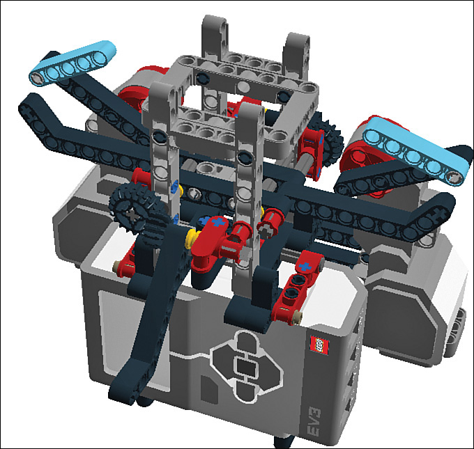
6. Project: Robot Flower
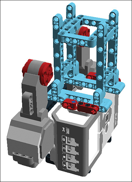
In this chapter you build another robot. This one is a Robot Flower that opens and closes its petals with the help of a pair of motors (see Figure 6.1). I show you how to build the Flower and then show you two ways to control it. The first method uses the usual EV3 Intelligent Brick, with the program moving the motors incrementally as commanded by the program. The petals begin the day tightly closed and then gradually open up as the day progresses until they are wide open. The process then reverses so the flower closes up as the day wanes.

After the initial build, I show you how to use an Arduino microcontroller in place of the EV3 brick, opening up a whole new world of robot control techniques.
Robot Flower Mindstorms Build
Let’s begin the project by building the robot with all Mindstorms components. We’ll worry about the Arduino later!
Parts List
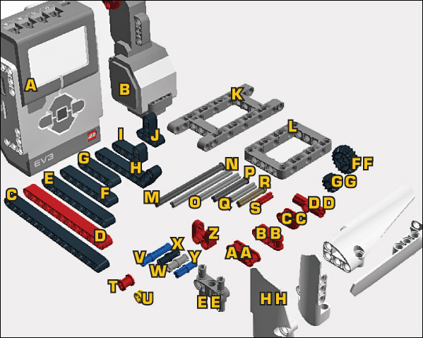
You need the following Mindstorms parts to build the Robot Flower, following along with Figure 6.2. As usual, you can find these in your Mindstorms set.
A. EV3 Intelligent Brick
B. 2X large motors
C. 2X 13M beams
D. 4X 11M beams
E. 4X 9M beams
F. 6X 7M beams
G. 6X 5M beams
H. 4X 3x7 angle beams
I. 2X 2x4 90-degree angle beams
J. 4X T-beams
K. 2X 5x11 chassis bricks
L. 1X 5x7 chassis brick
M. 3X 8m axles with end stop
N. 1X 7M axle
O. 4X 5M axles
P. 2X 4m axles with end stop
Q. 4X 3m axles
R. 2X 3m axles with knob
S. 2X 2m axles
T. 5X bushings
U. 2X half bushings
V. 8X 3m pegs
W. 55X connector pegs
X. 6X connector pegs without friction tabs
Y. 11X cross connectors
Z. 4X cross block fork
AA. 4X double cross blocks
BB. 2X cross blocks
CC. 2X 90-degree cross blocks
DD. 1X 180-degree angle element
EE. 1X 3m beam with pegs
FF. 2X Z20 gears
GG. 2X Z12 gears
HH. 2X each left and right 3x7 and 3x11 panels
Steps
Once you have gathered together the Mindstorms parts—or simply have your bin handy!—you can start building the flower.
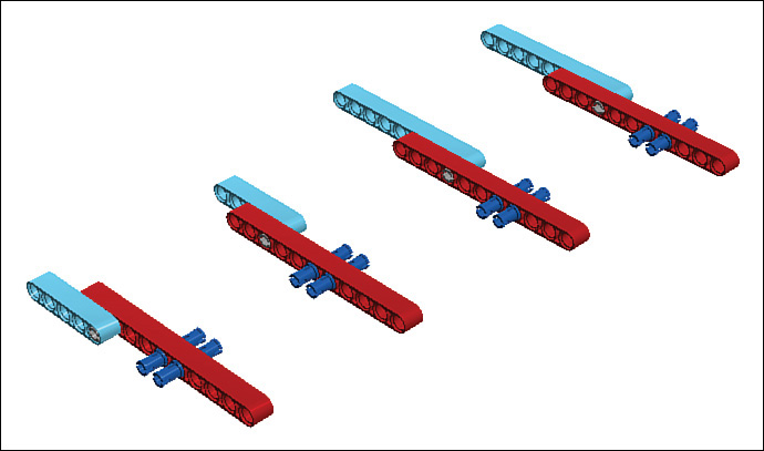
STEP 1 Let’s begin by building the flower petals. Grab four red 11M beams, and add 3M pegs and gray no-friction connector pegs, as shown in Figure 6.3. They’re just like the regular black kind but lack friction ridges allowing elements to rotate freely.

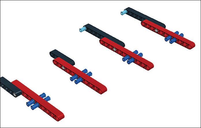
STEP 2 Attach two 5M beams and two 9M beams to the no-friction pegs while noting that the top two assemblies are identical, but the bottom two are not (see Figure 6.4).
STEP 3 Insert two more of those nifty gray connector pegs. Your assemblies should look like Figure 6.5.
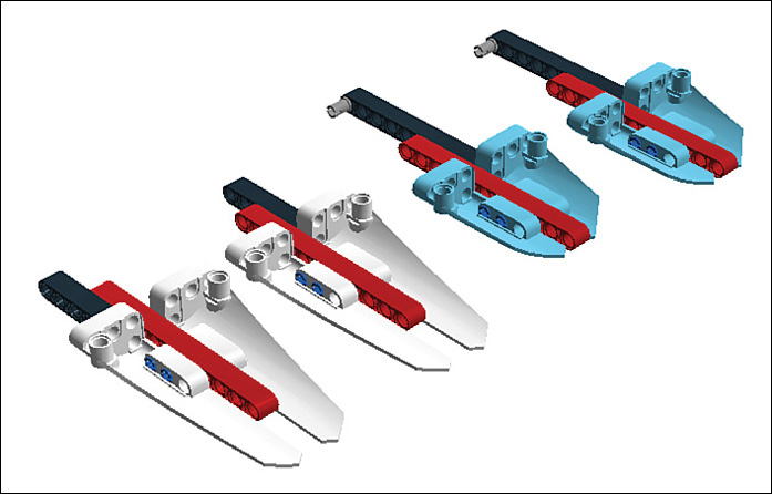
STEP 4 Next, add the 3x11 panels (as they are generically called) to the 3M connector pegs, as shown in Figure 6.6.

STEP 5 Attach the 3x7 panels to the other pair of assemblies (see Figure 6.7). Set aside the petals for now—we’ll focus on the main build for now and then add the petals at the end.
STEP 6 Attach a pair of 7M beams to the bottom of the EV3 brick, as shown in Figure 6.8. Use four connector pegs to secure them.

STEP 7 Insert four connector pegs and two cross connectors as you see in Figure 6.9.

STEP 8 Connect a pair of large motors to the pegs you just added, as shown in Figure 6.10.
STEP 9 Secure the motors with a pair of 13M beams, each part held in position by a connector peg at either end. Figure 6.11 shows how it should look.
STEP 10 Insert four connector pegs and two cross connectors as shown in Figure 6.12.
STEP 11 Attach two 2M and two 3M cross blocks. It should look like Figure 6.13.
STEP 12 Let’s switch things up a bit and work on the main chassis of the robot. Grab a pair of 5x11 chassis bricks and add a bunch of connector pegs as shown in Figure 6.14.

STEP 13 Connect the two 5x11 chassis bricks with a 5x7 chassis brick (see Figure 6.15).
STEP 14 Add four T-beams to the chassis bricks as shown in Figure 6.16.

STEP 15 Insert eight connector pegs to the bottom of the T-beams, as shown in Figure 6.17.
STEP 16 Add a pair of 9M beams to help stabilize the assembly (see Figure 6.18).
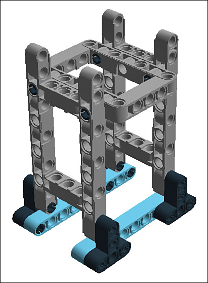
STEP 17 Set the assembly you just built on top of the Intelligent Brick, as shown in Figure 6.19. Don’t worry, you secure it the next step!
STEP 18 Secure the chassis with a series of cross axles. For the front of the robot (where you find the screen on the EV3), insert a pair of 3M cross axles with knobs into the cross blocks. The back of the chassis is secured with two 4M cross axles with end stops, with a 180-degree angle element trapped in between. It should look like you see in Figure 6.20.

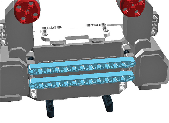
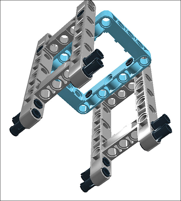
STEP 19 Next, add a pair of 7M beams connected to each other with a 3M beam with snaps. As you look at Figure 6.21 you’re probably wondering how this new assembly attaches to the main one. Just hold it there with your fingers for now; you attach it in the next step.
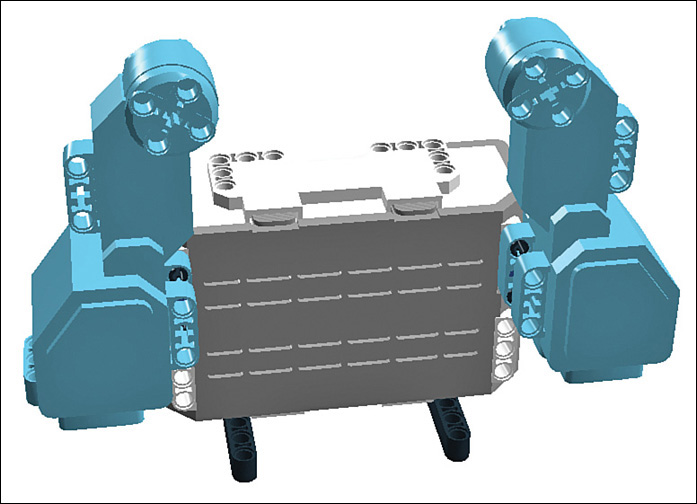
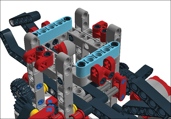
STEP 20 Secure the 7M beams with a pair of 8M cross axles with end stops. Note that one axle goes in one way, and the other axle inserts from the opposite side. Also note the pair of half bushings serving as spacers toward the front of the robot. Figure 6.22 shows how it should look.
STEP 21 Slide bushings onto the ends of the 8M cross axles you just added, as shown in Figure 6.23.
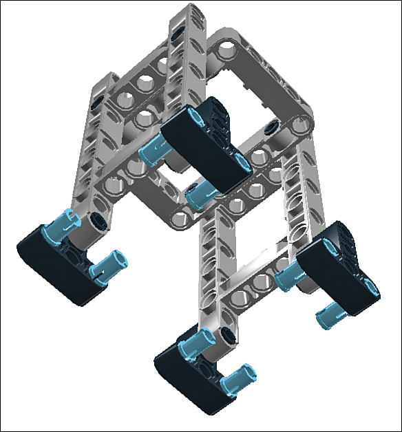
STEP 22 Let’s insert eight connector pegs. Put two in each motor’s hub, as shown in Figure 6.24, plus two in the horizontal beams of both of the 3x11 chassis bricks.

STEP 23 Attach two 2x4 angle beams to the pegs you just added (see Figure 6.25).

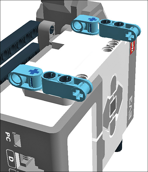
STEP 24 Insert a red 2M cross axle in the cross hole at the end of the 2x4 angle beams. Then add a blue cross connector peg to each angle beam, as shown in Figure 6.26.
STEP 25 Add six cross-connectors: Two go in each 5x11 chassis brick. The pegs visible on the back of the assembly mirror those in the front (see Figure 6.27).

STEP 26 Add double cross blocks to the cross connector pairs you just placed on the chassis bricks. You can see how it should look in Figure 6.28.
STEP 27 Slide an 8M axle with end stop through one of the double cross blocks you just added, trapping a Z20 gear and a 3x7 angle beam along the way, as shown in Figure 6.29. Secure the end with a bushing.

STEP 28 Rotate the model and repeat the process on the other side, as shown in Figure 6.30. Note that the gear assemblies you added this step and the last mirror each other, so one gear is in front and one is in back.

STEP 29 Next, we work on a new assembly. Slide a double cross block onto a 6M axle, as shown in Figure 6.31. Secure the double cross block with a bushing on one side and a half bushing on the other.

STEP 30 Slide a 3x7 angle beam onto the axle, as shown in Figure 6.32.
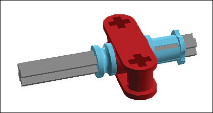
STEP 31 Finish off the assembly with a Z12 gear on the end (see Figure 6.33). Now, make a second assembly just like the first one! You want two of these assemblies.

STEP 32 Attach the two gear assemblies you just built to the 2x4 angle beams sticking out of the chassis in front and back. Figure 6.34 shows how it should look.
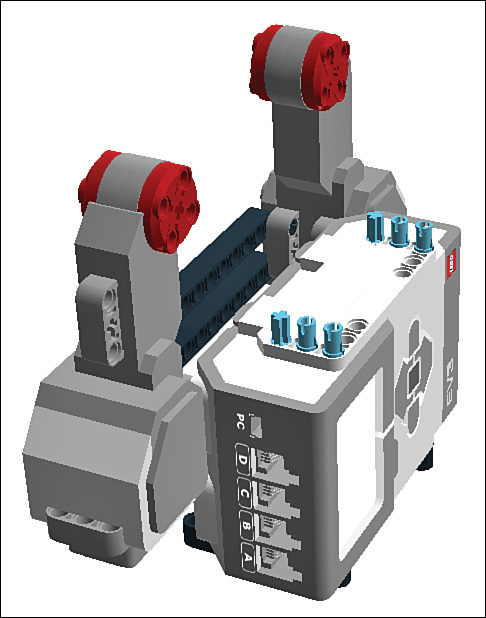
STEP 33 Next, snap a pair of 7M beams onto the motor hubs, as shown in Figure 6.35. While you’re in the neighborhood, insert a pair of gray no-friction pegs to the ends of the beams.

STEP 34 Attach 5M beams to the gray pegs on the ends of the 7M beams you just added, allowing them to swing loosely (see Figure 6.36).
STEP 35 Insert a dozen connector pegs into the chassis bricks, as shown in Figure 6.37.

STEP 36 Attach four cross block forks to the chassis bricks (see Figure 6.38). The petal assemblies you created will attach to the forks in a future step.

STEP 37 Insert a pair of 5M beams as shown in Figure 6.39.
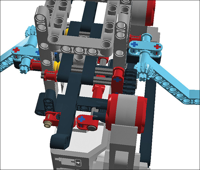
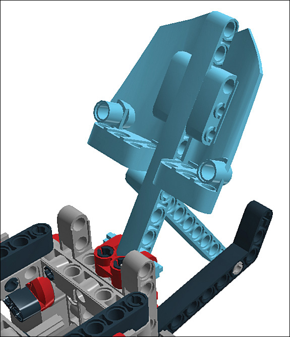
STEP 38 Let’s add the two smaller petals (the ones built with the 3x7 panels) to the front and back forks. The red 11M beam attaches to the fork, secured with a 3M axle, while its support beam connects to the 3x7 angle beam. Figure 6.40 shows how it should look.
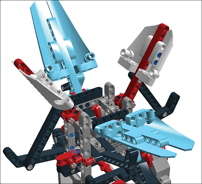
STEP 39 Attach the left and right petals, which have the longer 3x11 panels. The red beams attach to the remaining two forks using 3M axles, as shown in Figure 6.41.
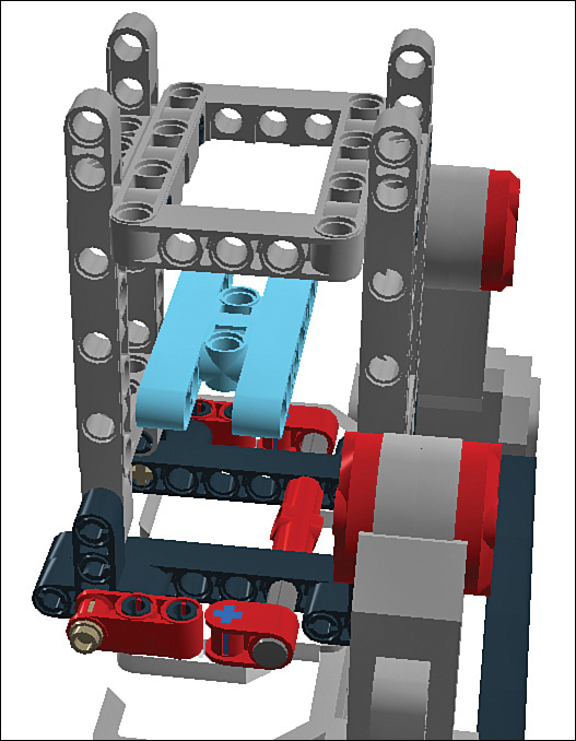
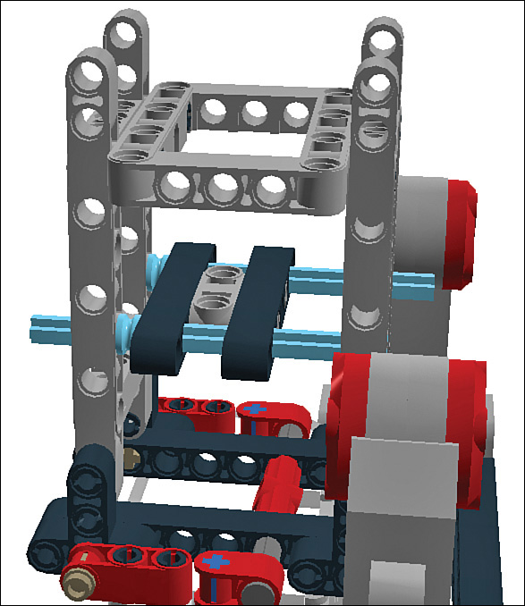
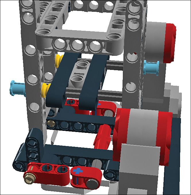
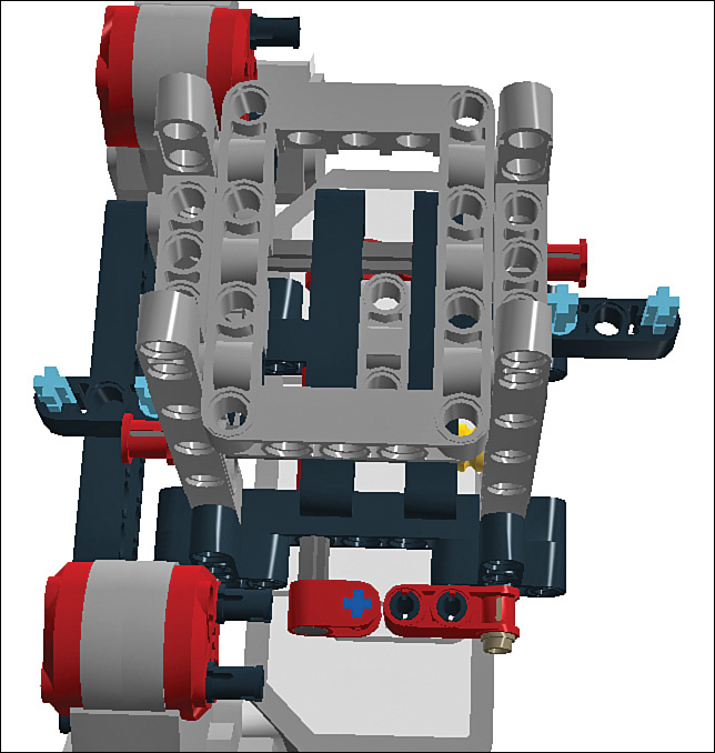
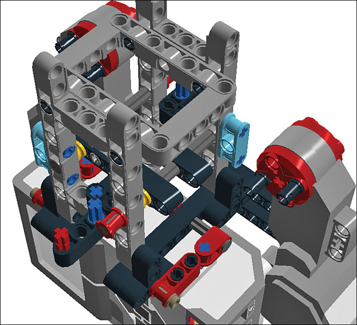
STEP 40 Finally, we need to secure the support beams for the big petals. This is kind of a complicated step and I had a hard time illustrating it in my design program, so instead I’m showing a photo of the robot that demonstrates how to connect things (see Figure 6.42).
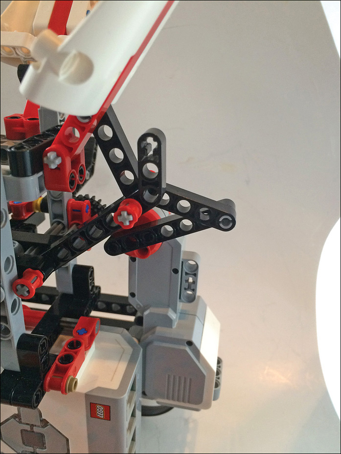
There are three beams that get connected together with a 5M axle: the end of the 5M beam you added in Step 35, the end of the petal’s support beam, and the 3x7 angle beam you added in Step 31. Secure the ends of the axle with bushings and then repeat the process with the final petal. You’re done!
Program the Robot Flower
Once the build is complete, you can focus on writing the Mindstorms program.
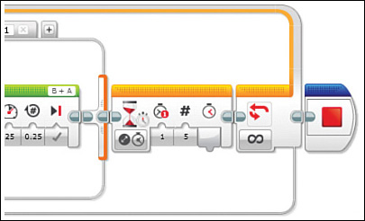
STEP 1 Drag a Variable block out of the palette and place it as you see in Figure 6.44. Name the variable “hours,” give it a default value of 0, and make the variable Write and Numeric.

STEP 2 Drop in a Loop block as shown in Figure 6.44. Keep the default loop name of 01.

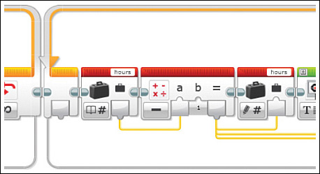
STEP 3 Place three blocks in your newly created loop: First, add another Variable block, though set this one to Read. Next, add a Logic block set for addition with the first number pulled from the Variable block and the second number set at the default of 1. Finally, drop another Variable block set to Write, with the input coming from the output of the Logic block. These three blocks increment the variable hours by adding 1 to it every time the loop cycles. Figure 6.45 shows how it should look.

STEP 4 Next, drop a Display block into the loop as shown in Figure 6.46. This is purely for diagnostic purposes and merely displays the current value of “hours” on the EV3’s screen. You can totally ditch this block without affecting anything. Set the Display block to Text-Pixels and then click on the default text value (“Mindstorms”) to Wired, allowing you to display the result of the Logic block’s computations with the help of a data wire.

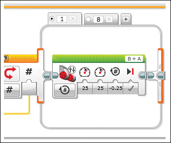
STEP 5 Drag a Switch block from the palette and drag it into the loop. You want tabbed viewing, Numeric, with one cell set to 1 (with default selected) and one cell set to 8. Drag in another wire from the Logic block to tell the Switch the current “hours” value.
In the “1” cell, add a Move Tank block and set it to 25% power on both, with rotations set to -0.25. The Move Tank block controls two motors simultaneously, which works great for us.
This is the default action that takes place every time the loop cycles: Both motors turn a quarter revolution, opening the flower a tiny bit. Because it’s the default, this cell triggers anytime the variable isn’t an 8. Note that if you ever want to change the number of loops (hours), simply change the number in the tab. Figure 6.47 shows how it should look.
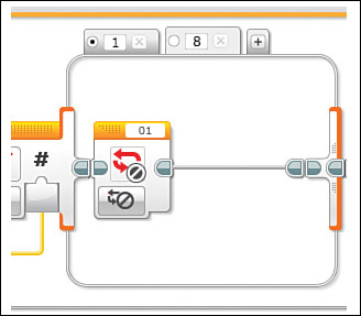
STEP 6 Next, let’s populate the other cell of the Switch block, as shown in Figure 6.48. The “8” cell triggers when the loop cycles through until “hours” is an 8. When that happens, we want the loop to end. Drag a Loop Interrupt into the cell. The default loop designation of 01 is correct.
STEP 7 The loop is not yet complete! Let’s add one more block: a Timer, shown in Figure 6.49. The Timer delays the robot’s movements so that they take place once an hour.

Set it to Change - Time, and then put 5 down for the duration. But wait, I said an hour! Ever try debugging a robot when it only moves once an hour? The default of 5 seconds suffices for now, and when you have the flower working the way you want, change the duration to 3600, the number of seconds in an hour. You’re done with the loop!
STEP 8 The loop you just completed opens the flower throughout the course of 8 hours. The next step is to make it close again. Duplicate the loop by selecting it (the boundaries turn blue) and cutting and pasting it next to the other, as you see in Figure 6.50. Change its name to 02.

STEP 9 Obviously we need to change the settings so the motors move in the opposite direction. First, however, let’s change the Logic block for the new loop so that it decrements—subtracts 1 with each loop cycle. Simply change the setting to Subtract. The plus turns into a minus, as shown in Figure 6.51.
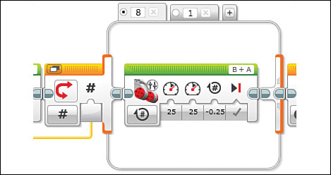
STEP 10 Now for the Switch block, shown in Figure 6.52. First, renumber the two tabs, so 1 becomes 8 and vice versa. Since the variable hours is counting down, 8 becomes the default and 1 is the end. The next thing you need to do is change the motor’s rotation by giving it a positive rotation number. Finally, the Loop Interrupt should be changed to interrupt Loop 02.
STEP 11 Finally, let’s place an End Program block, which stops the program once the second loop has run. It’s optional; if you want your flower to cycle indefinitely, don’t add it. Put the End Program block outside the second loop, as shown in Figure 6.53.
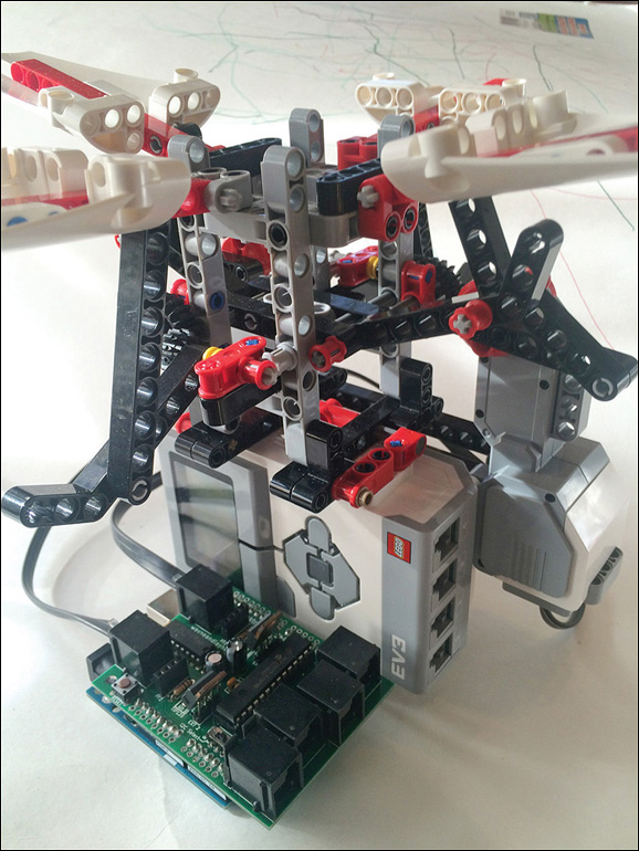
Substituting the Arduino
Let’s mix things up big time by using an Arduino in place of the EV3 brick (see Figure 6.54). Oh, we leave the physical brick in place to support the flower, but the Arduino controls the motors with the help of a Bricktronics Shield, mentioned in Chapter 5, “Hacking LEGO II: Alternate Controllers.” It serves as an interface between the Arduino and the Mindstorms motors.
However, I’m going to begin with a brief Arduino tutorial. This isn’t a book about Arduinos, however, so I’m not going to go into too much depth. If you’re dying to learn more, check out my book Arduino for Beginners (Que 2013), but otherwise I’m going to keep it succinct.
Quick and Dirty Arduino
Here’s what you need to get going:
Read this How-To
Two solid documents to help you learn about the basics:
http://www.arduino.cc/en/Main/Howto
http://www.arduino.cc/en/Tutorial/Foundations
Buy an Arduino
You can purchase an Arduino UNO at SparkFun.com, P/N 11021 among many other sites and physical stores.
http://www.arduino.cc/en/Main/ArduinoBoardUno
Download the Environment
You need to download the platform’s development environment, available for Mac, Windows, and Linux:
http://www.arduino.cc/en/Main/Software
Learn About the Environment
Once you have it installed, familiarize yourself with its features:
http://www.arduino.cc/en/Guide/Environment
Parts
To equip your Robot Flower with an Arduino, you need the following parts:
![]() Arduino UNO—As mentioned, they are widely available.
Arduino UNO—As mentioned, they are widely available.
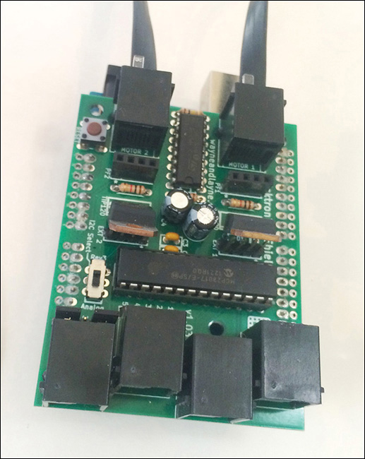
![]() Bricktronics Shield—Shown in Figure 6.55, available at http://www.wayneandlayne.com/bricktronics/.
Bricktronics Shield—Shown in Figure 6.55, available at http://www.wayneandlayne.com/bricktronics/.

![]() Power supply—SparkFun has a good one, P/N 298.
Power supply—SparkFun has a good one, P/N 298.
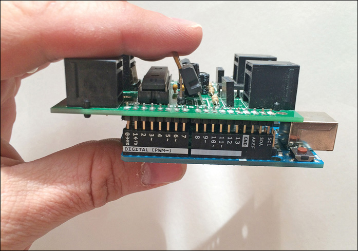
STEP 1 Plug the Bricktronics Shield on top of the Arduino, inserting the shield’s header pins into the Arduino’s female headers. It should nest neatly, as shown in Figure 6.56.
STEP 2 Plug the Mindstorms motors into the Bricktronics motor ports. These are the two ports by themselves, shown in Figure 6.57.
Programming the Arduino
Upload the following sketch to the Arduino. When the code has loaded, the board automatically launches the program.
#include <Wire.h>
#include <Bricktronics.h>
Bricktronics brick = Bricktronics();
PIDMotor l = PIDMotor(&brick, 1);
PIDMotor r = PIDMotor(&brick, 2);
void setup() // arduino sketches have a Setup, which runs once,
//and a Loop, which runs until the loop is broken.
{
Serial.begin(115200);
brick.begin();
l.begin();
r.begin();
}
void loop()
{
switch(hours) // switch works much like EV3's Switch block.
case 1: //the flower opens
l.set_speed(-75);
r.set_speed(-75);
delay(150);
l.set_speed(0);
r.set_speed(0);
delay(1000);
++hours; // increments the hours
if (hours=9) {
case = 2;
}
break;
case 2: //the flower closes
l.set_speed(150); //note the different settings vs. opening the flower.
//the robot needs more power to open vs. close, because it's fighting gravity.
r.set_speed(150);
delay(150);
l.set_speed(0);
r.set_speed(0);
delay(360000); // pauses the program for 1 hour
- -hours; // decrements the hours
if (hours=0) {
case = 1;
}
break;
}
Summary
Whew! In this rather long chapter, you had the opportunity to make a time-dependent robot flower model and program it with both Arduino and Mindstorms controllers. In Chapter 7, “Hacking LEGO III: Create Your Own LEGO Parts,” you explore one of my favorite aspects of LEGO hacking: creating your own beams, plates, and gears to interface with Mindstorms’ already robust assortment of elements.